MilDef Crete DT10 Notebook computer User Manual NOTEBOOK COMPUTER
MilDef Crete Inc. Notebook computer NOTEBOOK COMPUTER
UserManual.wiki
>
MilDef Crete
>
DT10 User Manual
Users Manual
Navigation menu
Upload a User Manual
Namespaces
Wiki Guide
HTML
PDF
Info
Views
User Manual
Discussion / Help
Navigation
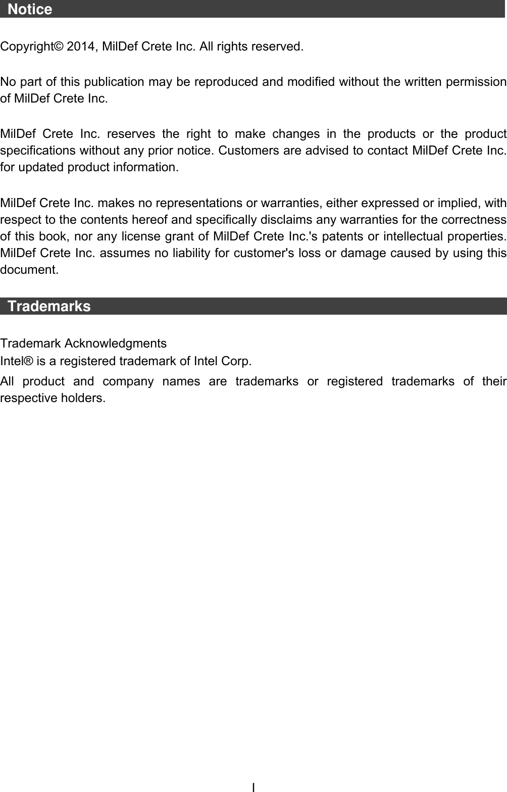

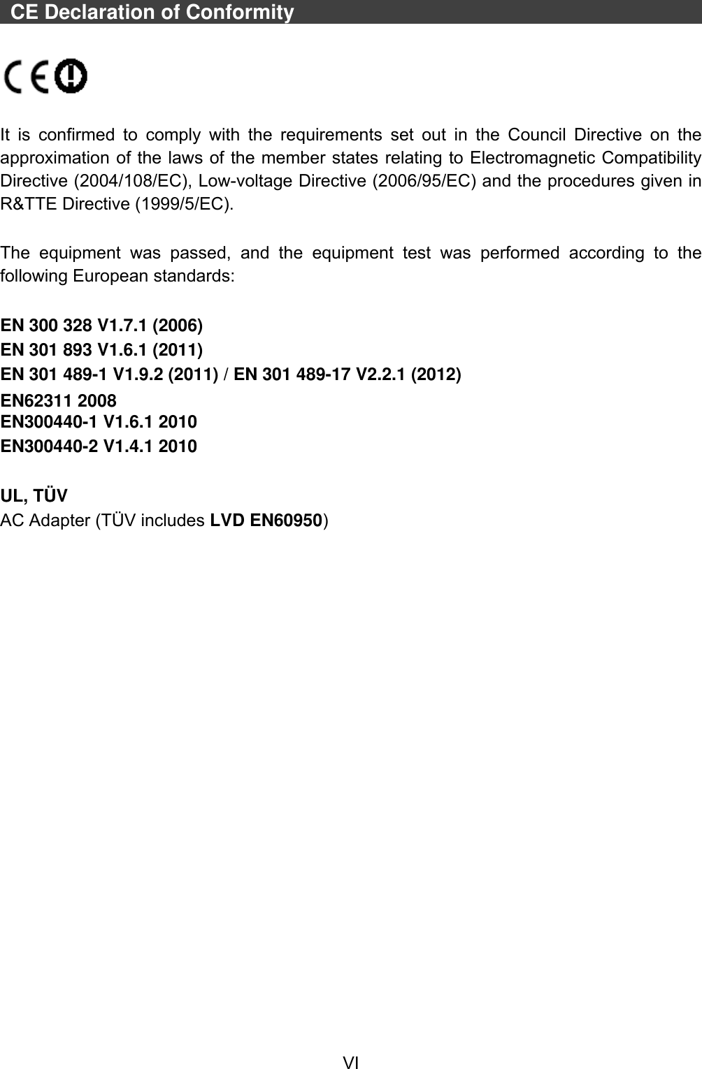

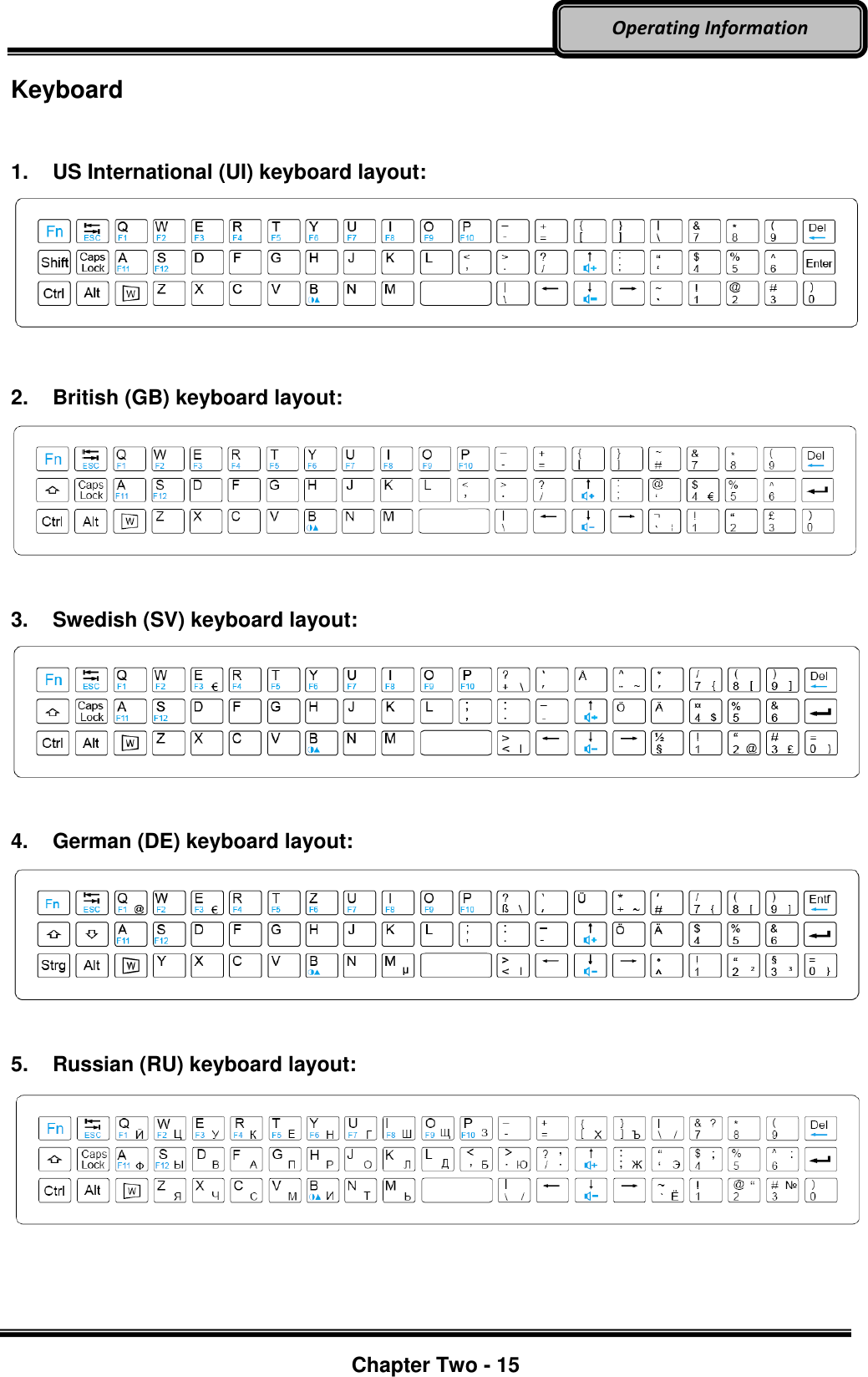
![Chapter Two - 16 Operating Information To perform 2nd layer combinational keystroke functions (keystroke functions printed in blue), press and hold the [Fn] key, then press the corresponding key combinations. A list of useful combinational button functions is provided below for operational reference: Key Description [Fn] + [B]: Switches your tablet computer’s keyboard backlight on or off. [Fn] + [↑]: Increases Audio Volume. [Fn] + [↓]: Decrease Audio Volume. [Fn] + [Del]: Backspace Key. [Fn] + [Tab]: Escape Key. [Fn] + [Q] ~ [S]: Function Key F1 ~ F12. Using Hard Disk Drive (HDD) / Optional Solid State Drive (SSD) Your tablet is equipped with 2.5” SATA II Hard Disk Drive (HDD), or optional Solid State Drive (SSD) for data storage. HDD/SSD is user removable, providing convenience and security. It can ONLY be removed while power is OFF. Note: Avoid dropping your HDD/SSD module. Do not expose it directly to high temperature, high humidity, and other hazardous environment. NEVER try to disassemble the module. Static discharge may destroy your device and data. Always pick up the module by touching the case only.](https://usermanual.wiki/MilDef-Crete/DT10/User-Guide-2389224-Page-29.png)
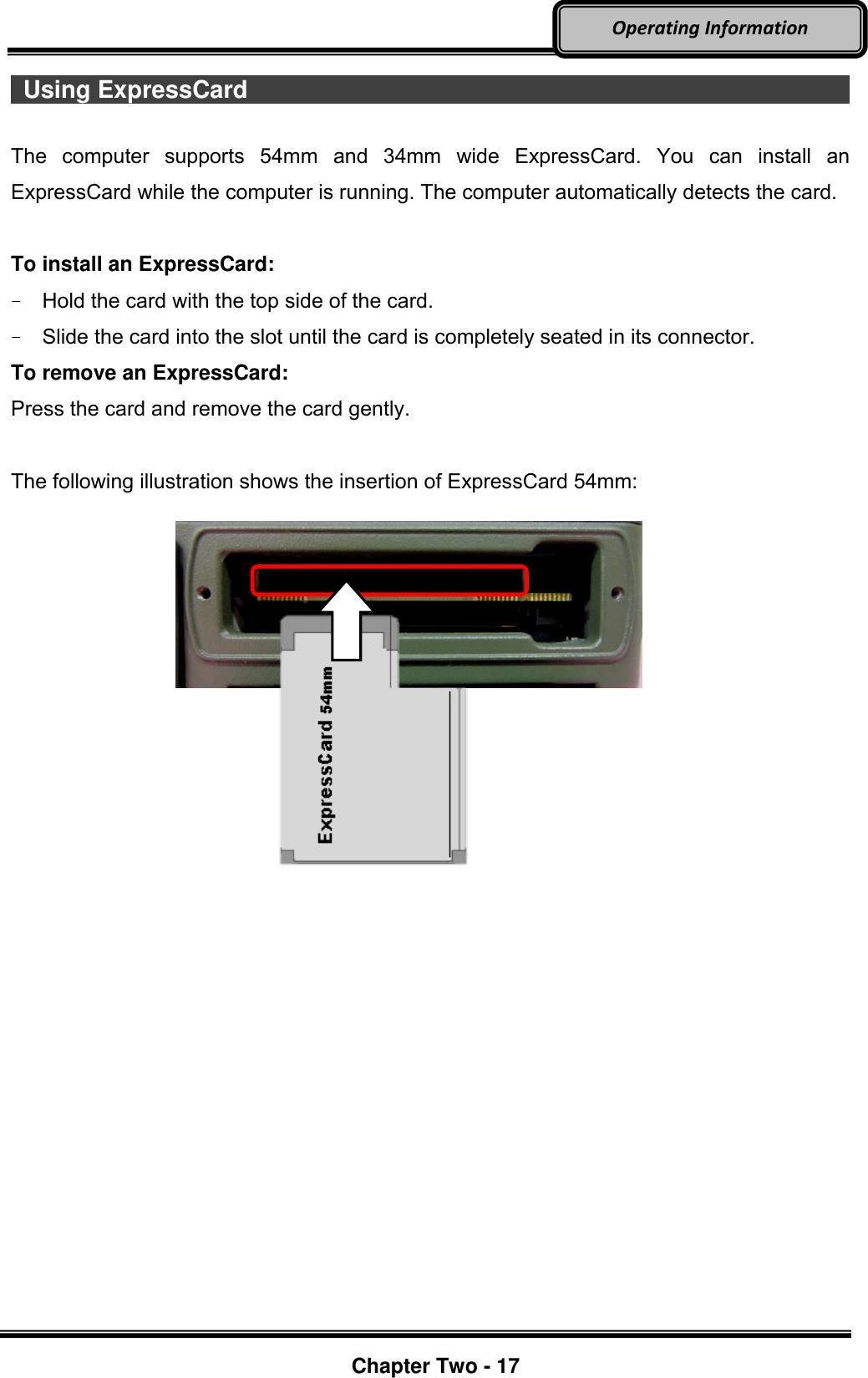
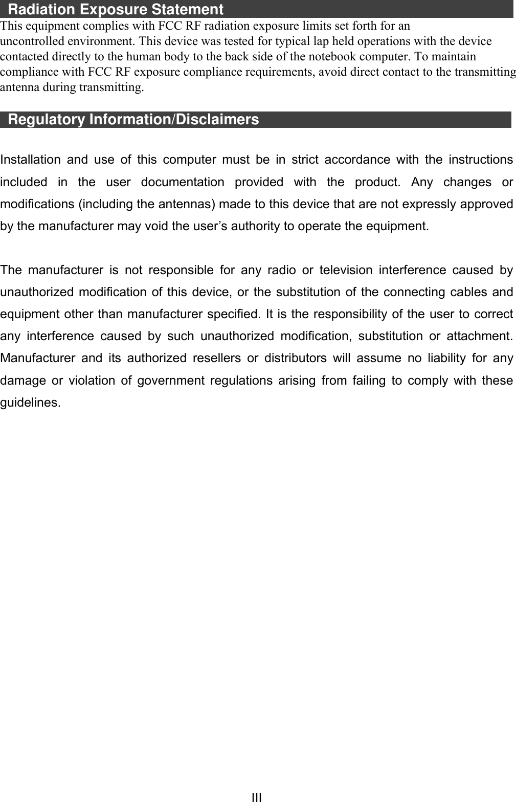
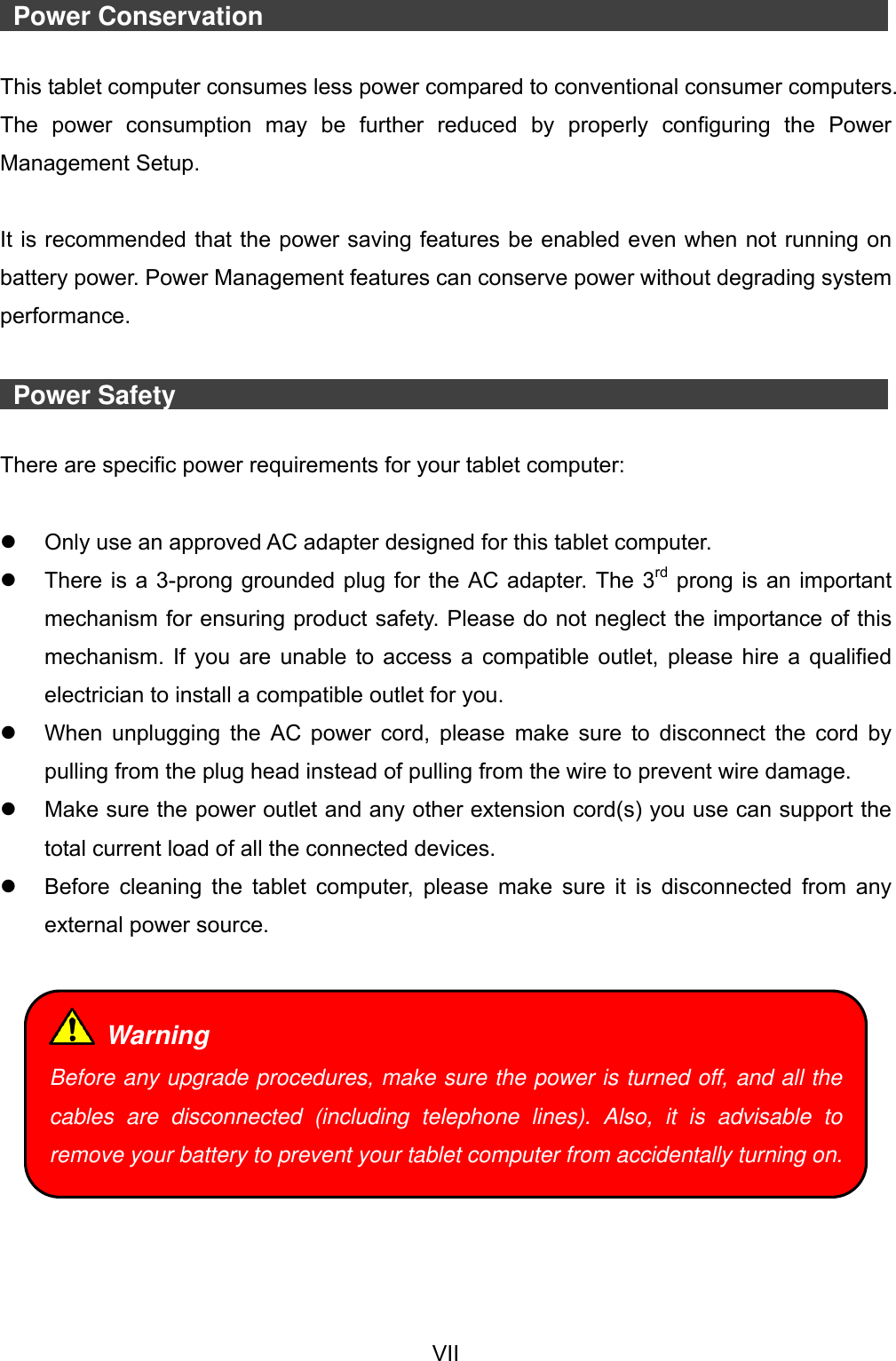
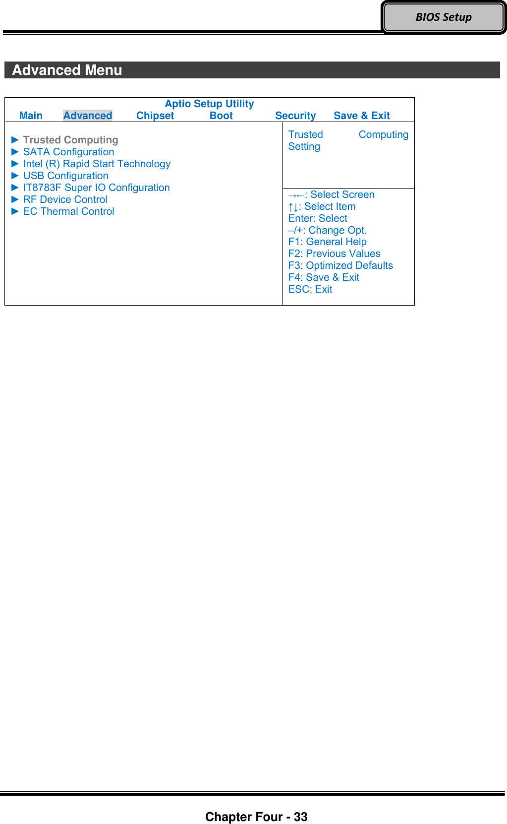
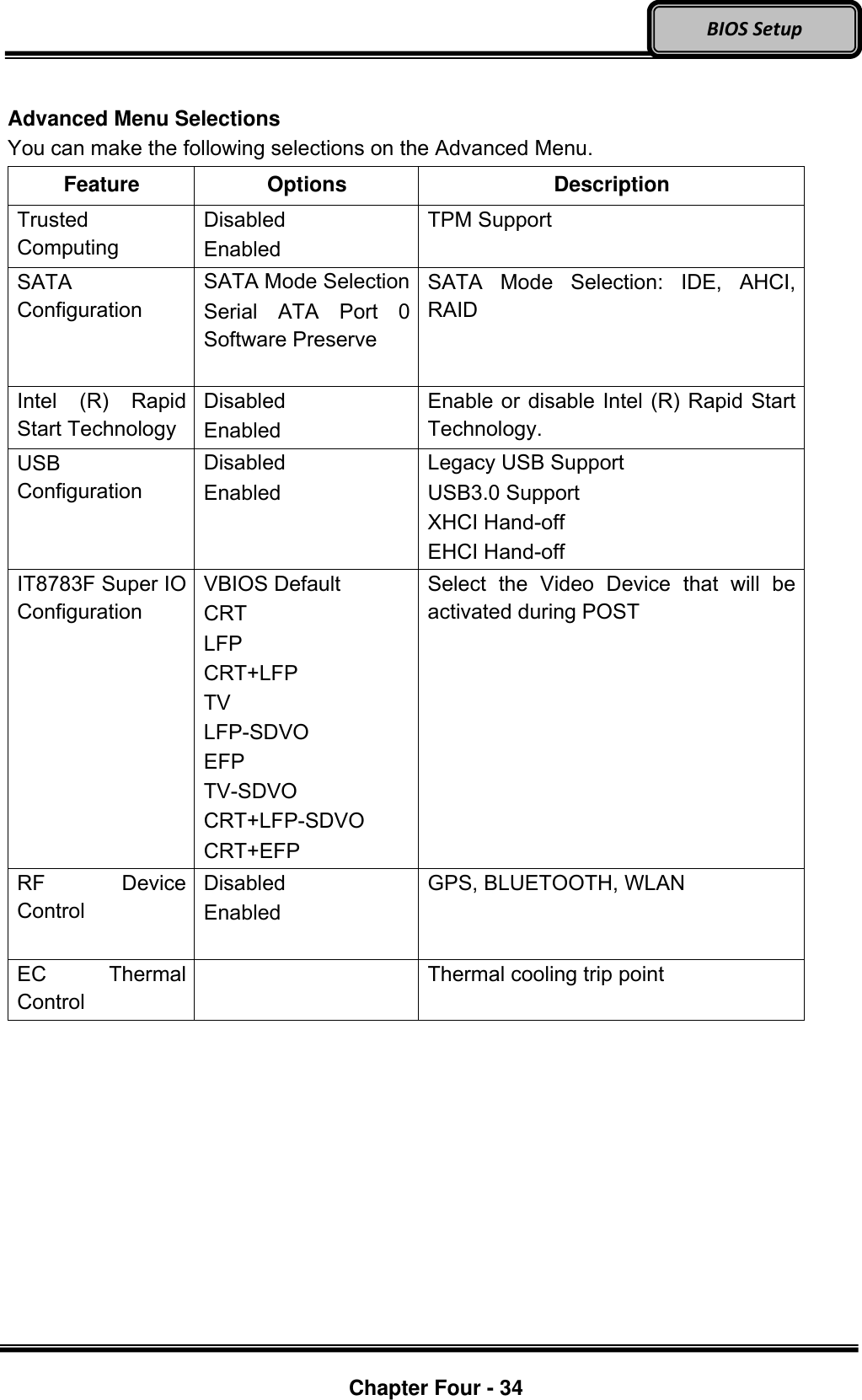
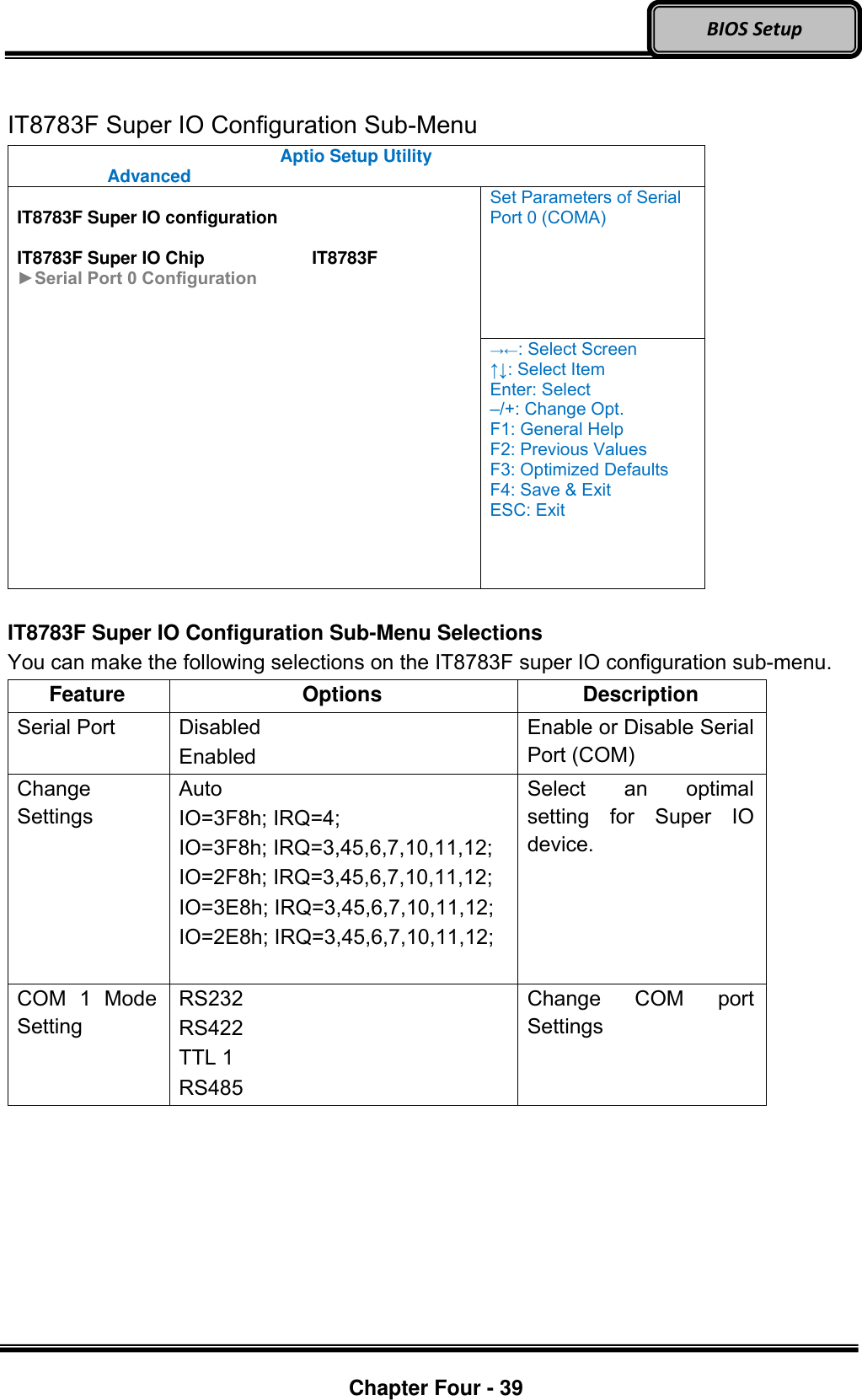
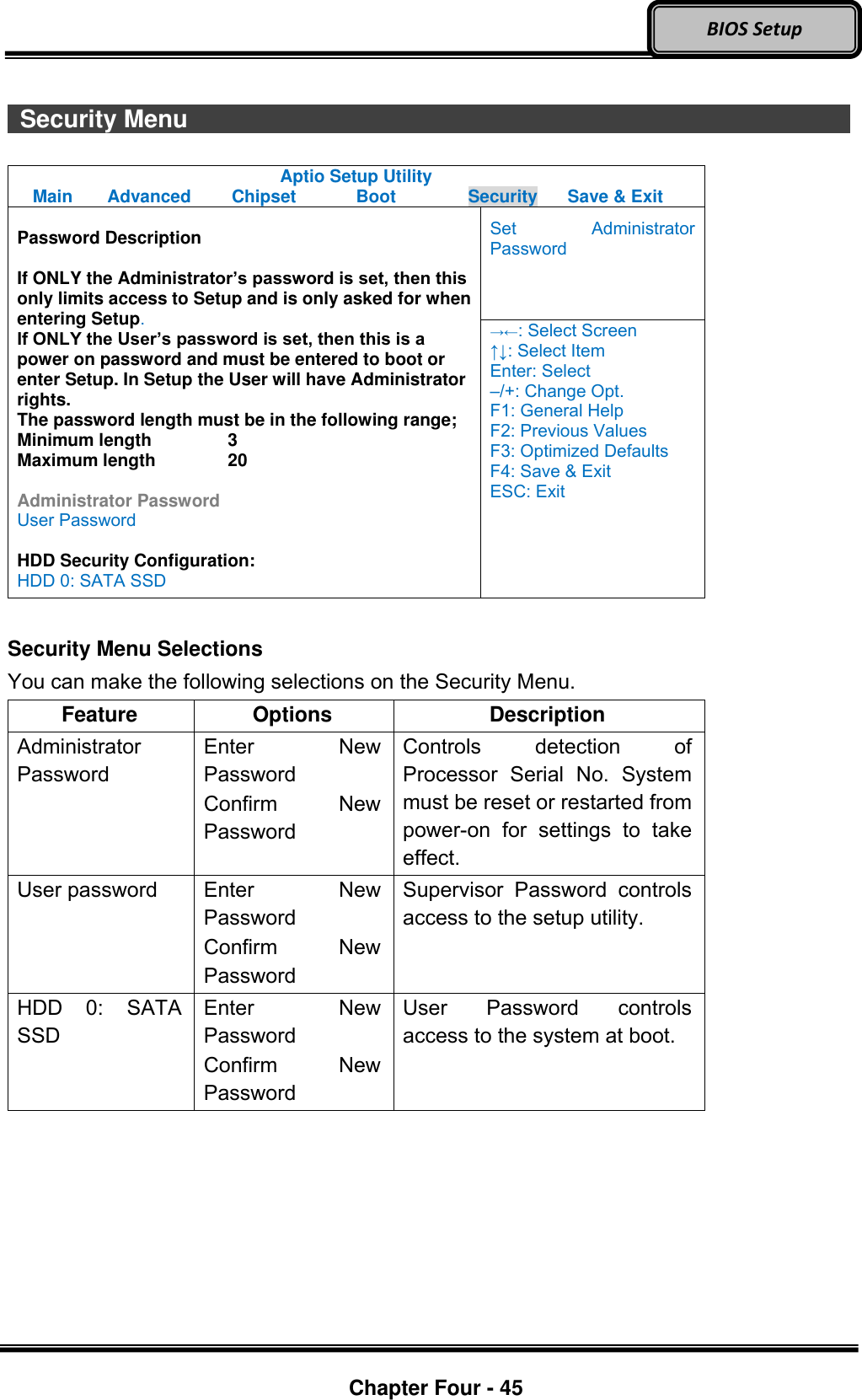
![Optional Devices Chapter Four - 32 BIOS Setup Chapter 4 - BIOS Setup Press [F2] at boot up to enter BIOS setup. Use arrow keys to select options and [+/-] to modify them. When finished, move to “Exit” and press [Enter] then confirm save by pressing [Y]. Main Menu Aptio Setup Utility Main Advanced Chipset Boot Security Save & Exit BIOS Information BIOS Vendor Core Version Compliancy Project Version Build Date and Time EC Version System Language [English] System Date [Wed 06/19/2013] System Time [16:19:20] Access Level Administrator Choose the system default language →←: Select Screen ↑↓: Select Item Enter: Select –/+: Change Opt. F1: General Help F2: Previous Values F3: Optimized Defaults F4: Save & Exit ESC: Exit Main Menu Selections You can make the following selections on the Main Menu. Use the sub-menus for other selections. Feature Options Description System Date MM/DD/YYYY Set the system date Month, Day, Year. System Time HH:MM:SS Set the system time Hour, Minute, Second. Note: The contents may vary depending on computer configurations. Incorrect settings may cause system malfunction. To correct it, restore the Optimized Defaults with F3.](https://usermanual.wiki/MilDef-Crete/DT10/User-Guide-2389224-Page-45.png)
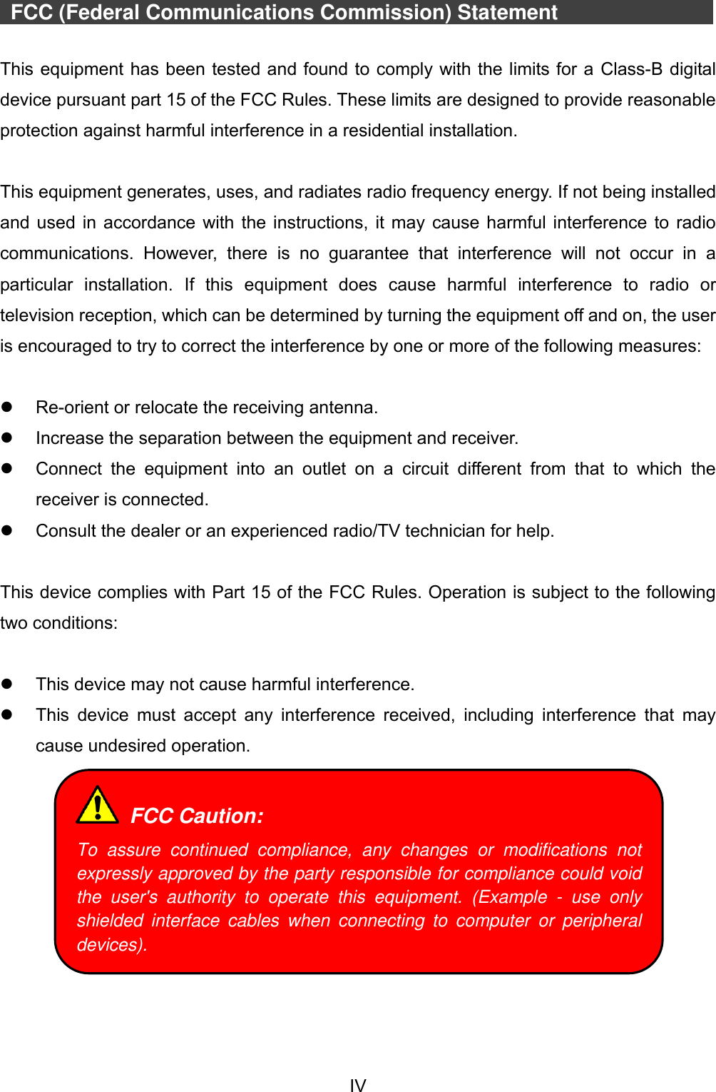
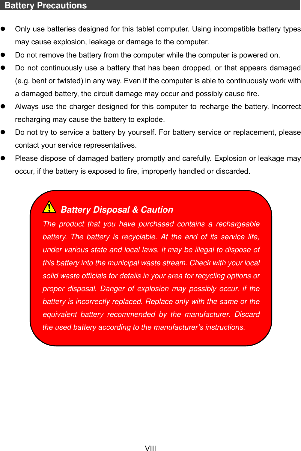
![Optional Devices Chapter Four - 35 BIOS Setup Trusted Computing Sub-Menu Aptio Setup Utility Advanced Configuration TPM SUPPORT [Disable] Current Status Information SUPPORT TURNED OFF Enables or Disables BIOS support for security device. O.S. will not show Security Device. TCG EFI protocol and INT1A interface will not be available. →←: Select Screen ↑↓: Select Item Enter: Select –/+: Change Opt. F1: General Help F2: Previous Values F3: Optimized Defaults F4: Save & Exit ESC: Exit](https://usermanual.wiki/MilDef-Crete/DT10/User-Guide-2389224-Page-48.png)
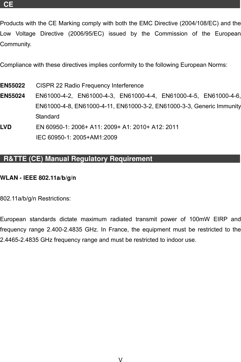
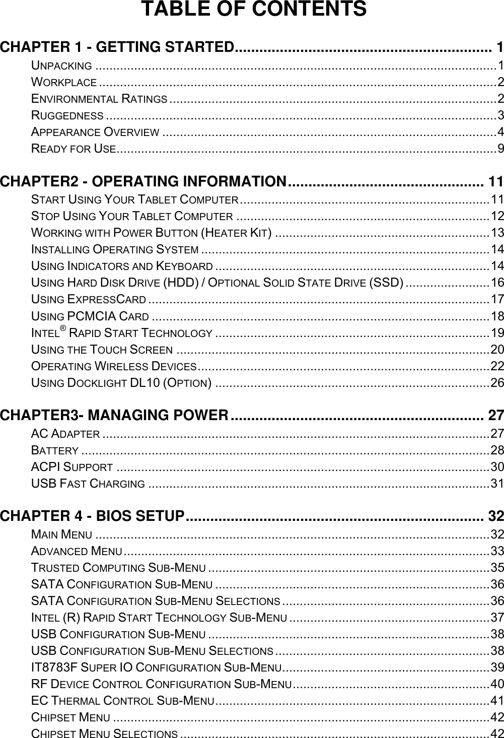
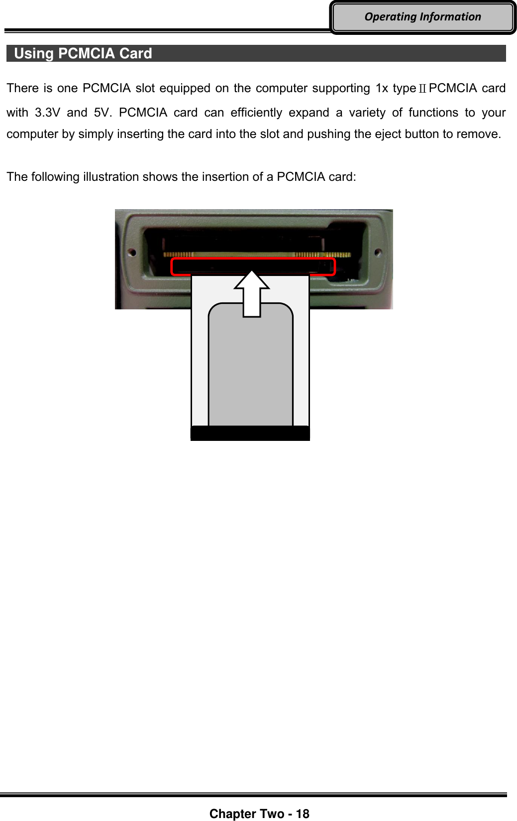
![Optional Devices Chapter Four - 36 BIOS Setup SATA Configuration Sub-Menu Aptio Setup Utility Advanced SATA Mode Selection [AHCI] Serial ATA Port 0 Empty Software Preserve Unknown Serial ATA Port 1 Empty Software Preserve Unknown Serial ATA Port 2 SATA SSD (120.0 Software Preserve SUPPORTED Determine how SATA controller(s) operate. →←: Select Screen ↑↓: Select Item Enter: Select –/+: Change Opt. F1: General Help F2: Previous Values F3: Optimized Defaults F4: Save & Exit ESC: Exit SATA Configuration Sub-Menu Selections You can make the following selections on the SATA configuration sub-menu. Feature Options Description SATA Mode Selection IDE AHCI RAID Port 0 Disabled Enabled Enable or Disable SATA Port Hot Plug Disabled Enabled Designates this port as Hot Pluggable](https://usermanual.wiki/MilDef-Crete/DT10/User-Guide-2389224-Page-49.png)
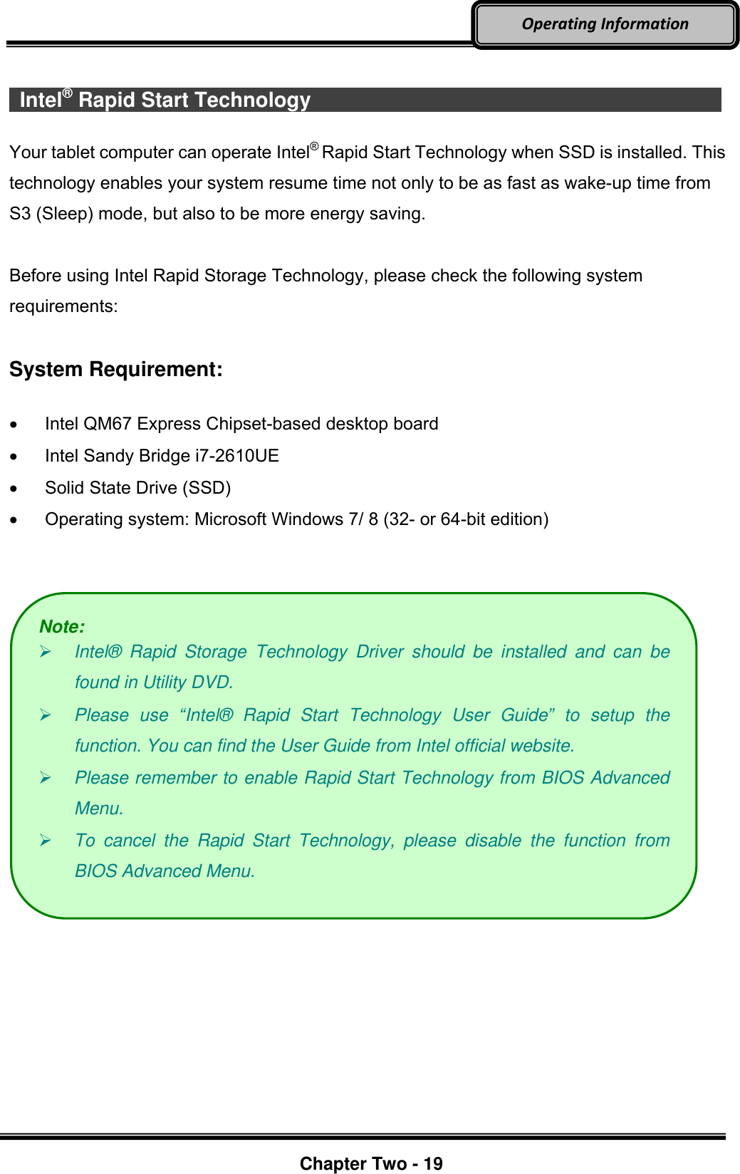
![Optional Devices Chapter Four - 37 BIOS Setup Intel (R) Rapid Start Technology Sub-Menu Aptio Setup Utility Advanced Intel (R) Rapid Start Technology [Disabled] Enables or disable Intel (R) Rapid Start Technology →←: Select Screen ↑↓: Select Item Enter: Select –/+: Change Opt. F1: General Help F2: Previous Values F3: Optimized Defaults F4: Save & Exit ESC: Exit](https://usermanual.wiki/MilDef-Crete/DT10/User-Guide-2389224-Page-50.png)
![Optional Devices Chapter Four - 38 BIOS Setup USB Configuration Sub-Menu Aptio Setup Utility Advanced USB Configuration USB Devices: 1 point Legacy USB Support [Enabled] USB3.0 Support [Enabled] XHCI Hand-off [Enabled] EHCI Hand-off [Disabled] Enables Legacy USB support. AUTO option disables legacy support if no USB devices are connected. Disable option will keep USB devices available only for EFI applications →←: Select Screen ↑↓: Select Item Enter: Select –/+: Change Opt. F1: General Help F2: Previous Values F3: Optimized Defaults F4: Save & Exit ESC: Exit USB Configuration Sub-Menu Selections You can make the following selections on the USB configuration sub-menu. Feature Options Description Legacy USB enabled Disabled Enabled Enables Legacy USB support. AUTO option disables legacy support if no USB devices are connected. DISABLE option will keep USB devices available only for EFI applications. Usn3.0 Support Disabled Enabled Enable/Disable USB3.0 (XHCI) Controller support. XHCI Hand-off Disabled Enabled This is a workaround for OSes without XHCI hand-off support. This XHCI ownership change should be claimed by XHCI driver. EHCI Hand-off Disabled Enabled This is a workaround for OSes without EHCI hand-off support. This EHCI ownership change should be claimed by EHCI driver.](https://usermanual.wiki/MilDef-Crete/DT10/User-Guide-2389224-Page-51.png)
![Optional Devices Chapter Four - 40 BIOS Setup RF Device Control Configuration Sub-Menu Aptio Setup Utility Advanced RF Device Control GPS STATUS Present GPS [Enabled] BT STATUS Present BLUETOOTH [Enabled] WLAN STATUS Present WLAN [Enabled] RF Device Control Setting →←: Select Screen ↑↓: Select Item Enter: Select –/+: Change Opt. F1: General Help F2: Previous Values F3: Optimized Defaults F4: Save & Exit ESC: Exit RF Device Control Configuration Sub-Menu Selections You can make the following selections on the RF Security Control sub-menu. Feature Options Description Wireless LAN Disabled Enabled Wireless Lan Control Enabled Wireless function GPS Disabled Enabled GPS Control Enabled GPS function BlueTooth Disabled Enabled BlueTooth Control Enabled Blue Tooth function](https://usermanual.wiki/MilDef-Crete/DT10/User-Guide-2389224-Page-53.png)
![Optional Devices Chapter Four - 41 BIOS Setup EC Thermal Control Sub-Menu Aptio Setup Utility Advanced EC Thermal Control Thermal cooling trip point [87 C] EC Thermal Control Setting →←: Select Screen ↑↓: Select Item Enter: Select –/+: Change Opt. F1: General Help F2: Previous Values F3: Optimized Defaults F4: Save & Exit ESC: Exit](https://usermanual.wiki/MilDef-Crete/DT10/User-Guide-2389224-Page-54.png)
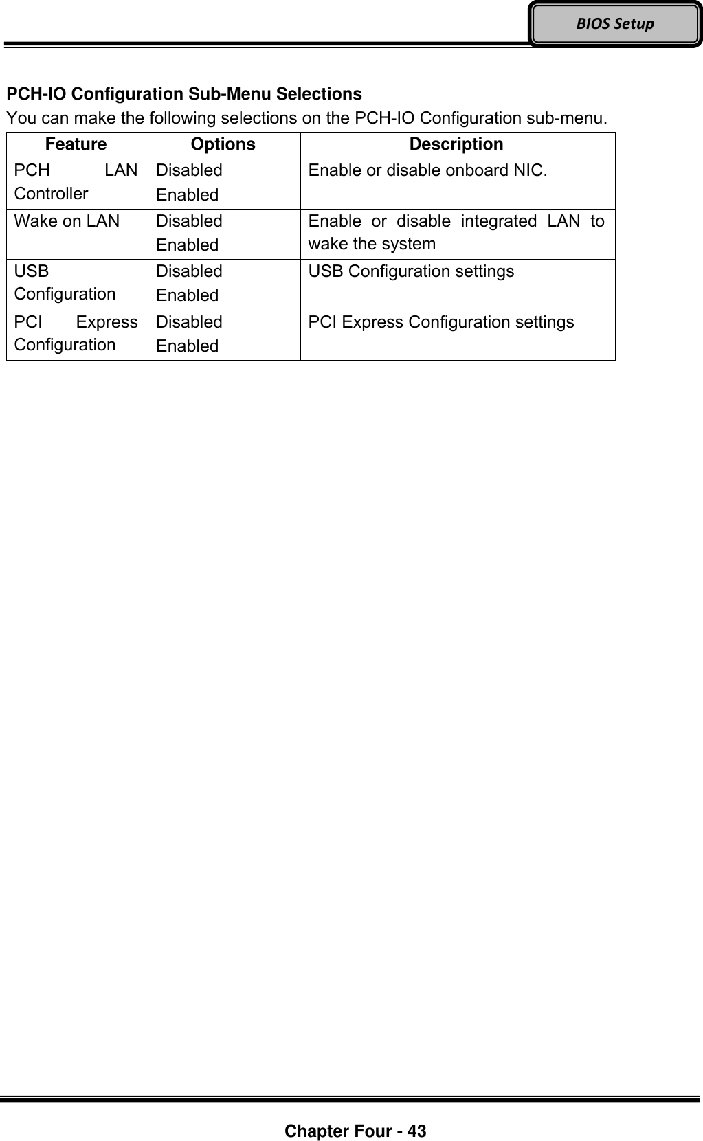
![Optional Devices Chapter Four - 42 BIOS Setup Chipset Menu Aptio Setup Utility Main Advanced Chipset Boot Security Save & Exit ► System Agent (SA) Configuration ► PCH-IO Configuration System Agent (SA) Parameters →←: Select Screen ↑↓: Select Item Enter: Select –/+: Change Opt. F1: General Help F2: Previous Values F3: Optimized Defaults F4: Save & Exit ESC: Exit Chipset Menu Selections You can make the following selections on the Chipset sub-menu. Feature Options Description System Agent (SA) Configuration System Agent (SA) Parameters PCH-IO Configuration PCH Parameter PCH-IO Configuration Sub-Menu Aptio Setup Utility Chipset Intel PCH RC Version 1.2.2.0 Intel PCH SKU Name QM67 Intel PCH Rev ID 05/B3 PCH LAN Controller [Enabled] Wake on LAN [Enabled] ► USB Configuration ► PCI Express Configuration Enable or disable onboard NIC. →←: Select Screen ↑↓: Select Item Enter: Select –/+: Change Opt. F1: General Help F2: Previous Values F3: Optimized Defaults F4: Save & Exit ESC: Exit](https://usermanual.wiki/MilDef-Crete/DT10/User-Guide-2389224-Page-55.png)
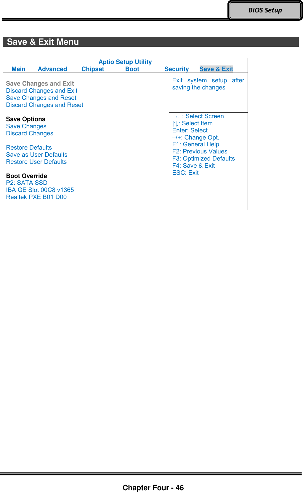
![Optional Devices Chapter Four - 44 BIOS Setup Boot Menu Aptio Setup Utility Main Advanced Chipset Boot Security Save & Exit Boot Option Priorities Boot Option #1 [P2: SATA SSD...] Boot Option #2 [IBA GE Slot 00C8 v...] Network Device BBS Priorities Hard Driver BBS Priorities Sets the system boot order →←: Select Screen ↑↓: Select Item Enter: Select –/+: Change Opt. F1: General Help F2: Previous Values F3: Optimized Defaults F4: Save & Exit ESC: Exit The system will try to boot from device on top then the 2nd and so on. If there is more than one device in each category, only the device on top of sub-menu can boot up. Boot Menu Selections You can make the following selections on the Boot menu. Feature Options Description Boot Option #1 Sets the system boot order Boot Option #2 Sets the system boot order Network Device BBS Priorities Set the order of the legacy devices in this group Hard Drive BBS Priorities Set the order of the legacy devices in this group](https://usermanual.wiki/MilDef-Crete/DT10/User-Guide-2389224-Page-57.png)

![Chapter Seven - 63 Optional Devices External USB Keyboard An optional 89-key external USB keyboard with LED backlight and IP rating of IP54 is available for your tablet computer. The detailed specification is provided below: 89-key layout emulates 101/102-key KB Life: >1 million times, water/dust protection up to IP54 Back-light illumination (backlight device: green LED) PS/2 compatible Trackpoint and mouse buttons Dimensions: 323.4 mm (W) x 172 mm (D) x 25 mm (H) Weight: 1.1 kg Track point The track point is functionally equivalent to a mouse. Pushing the track point may move the cursor on the screen. The 2 buttons act same as mouse buttons. Backlight Press [I-O] key for approximately 1 second turns keyboard backlight ON or OFF.](https://usermanual.wiki/MilDef-Crete/DT10/User-Guide-2389224-Page-76.png)