MicroGate WIT006 Witty RFID User Manual Witty EN
Microgate Witty RFID Witty EN
UserManual.wiki
>
MicroGate
>
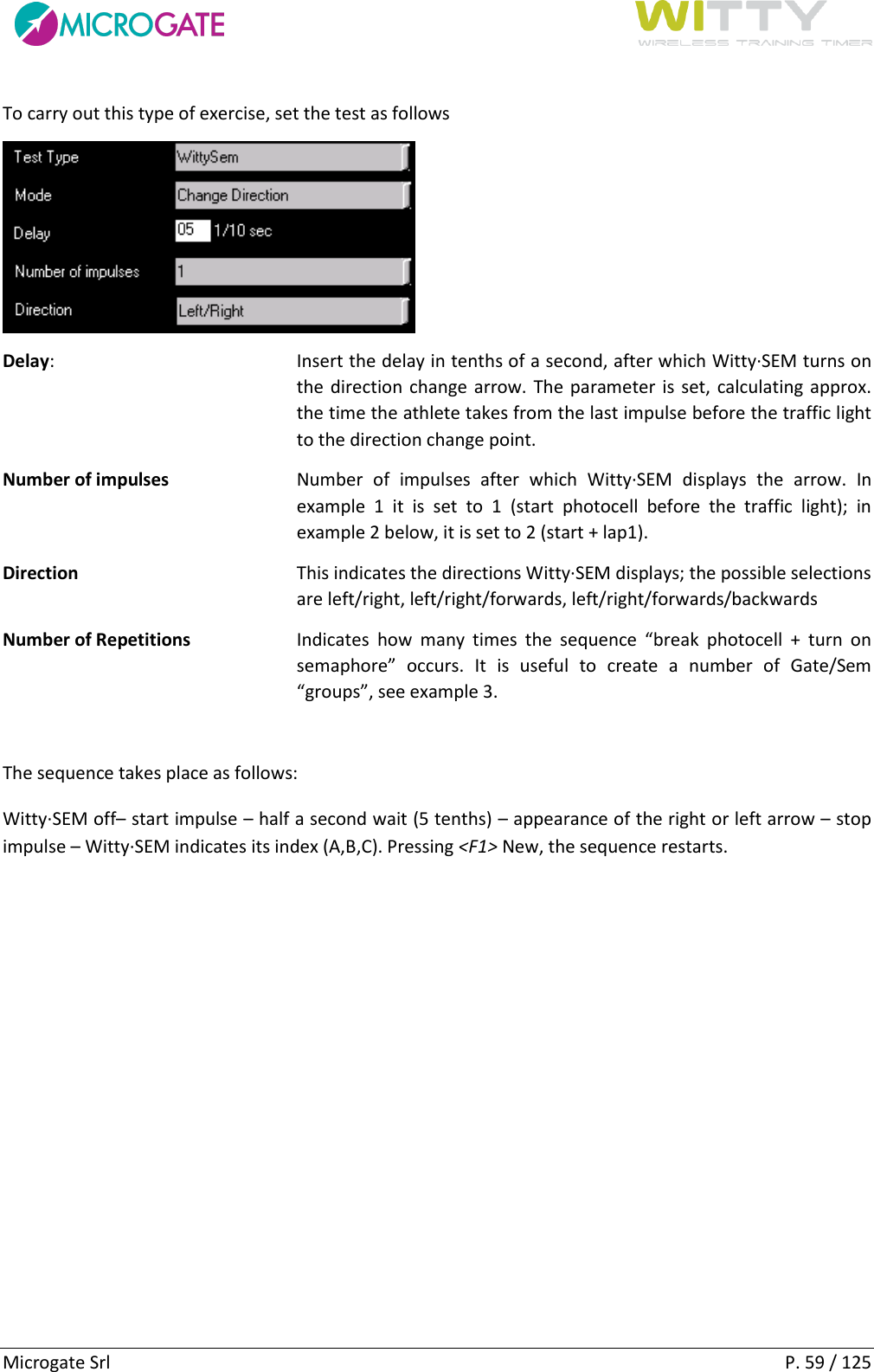
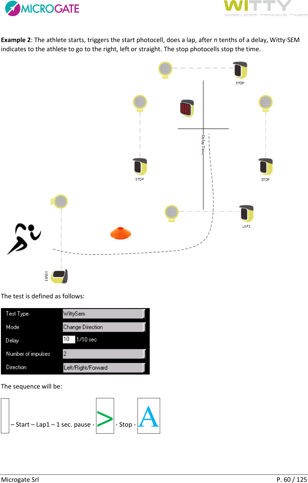
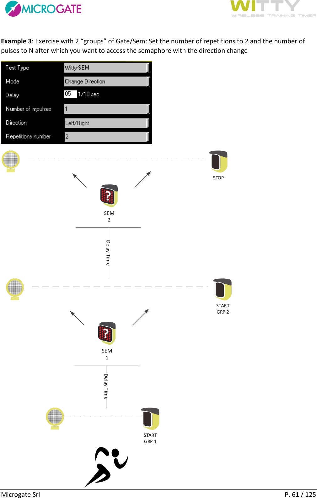
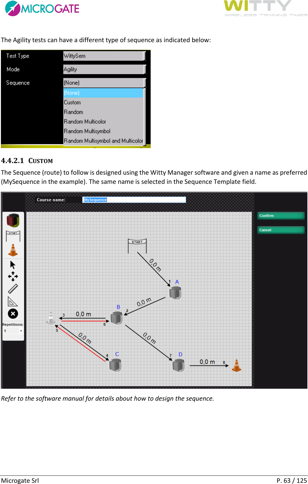
WIT006 User Manual
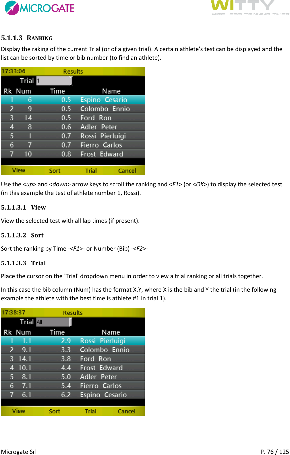
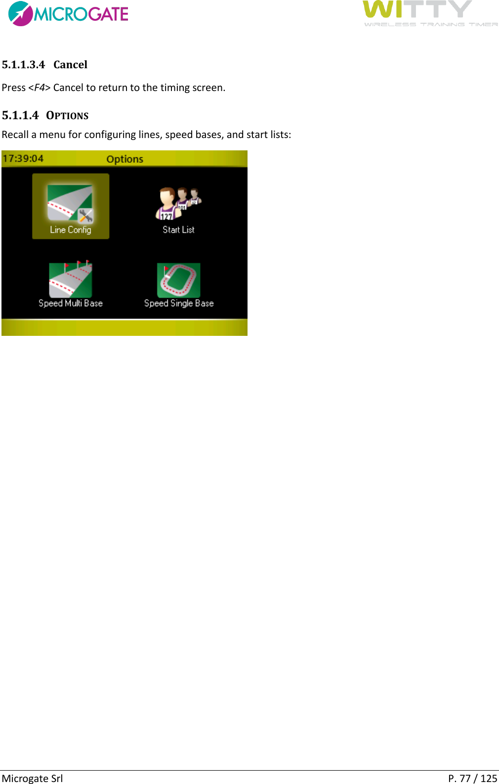
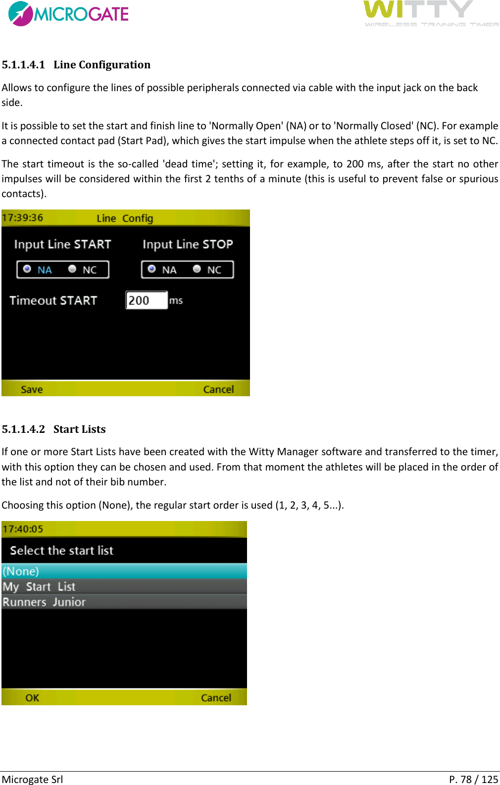
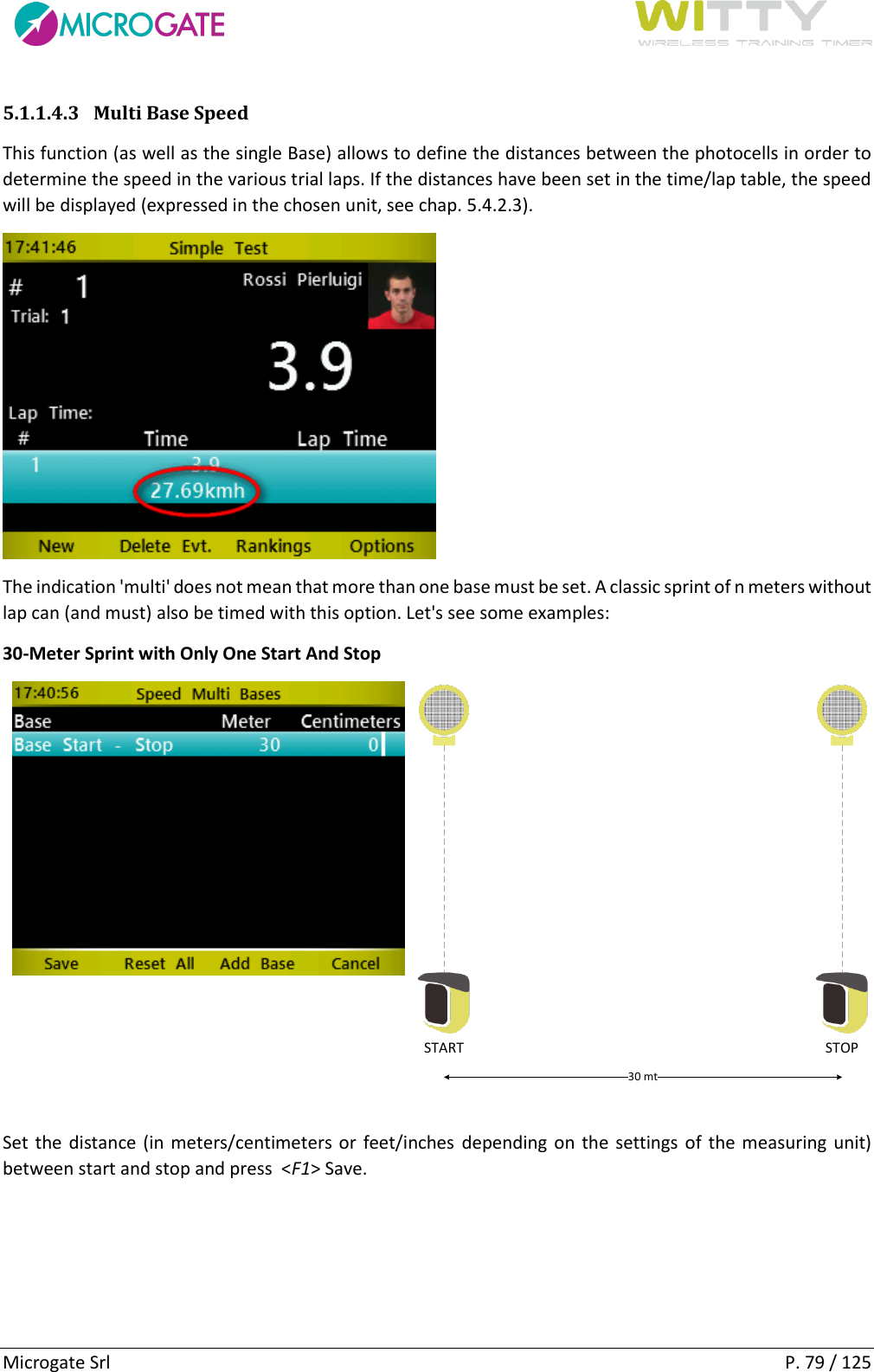
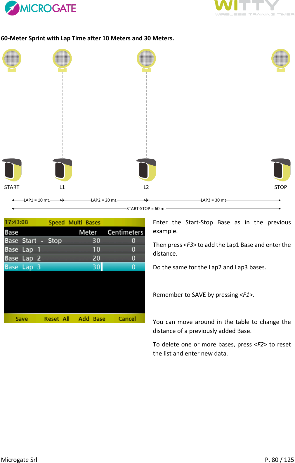
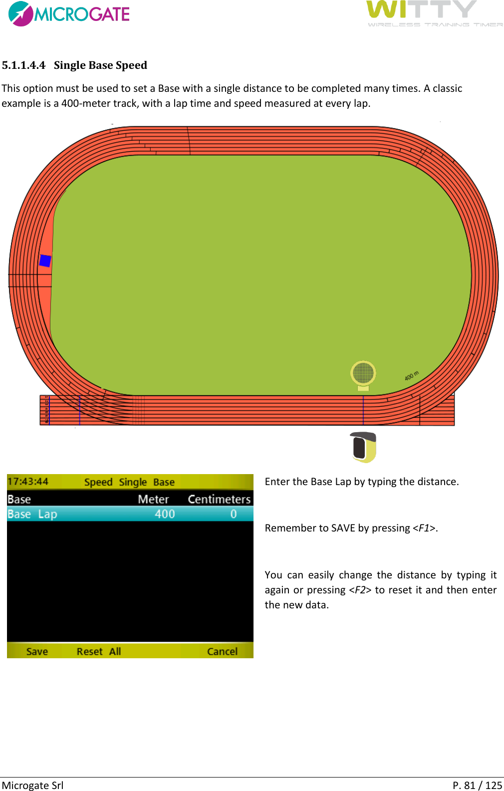
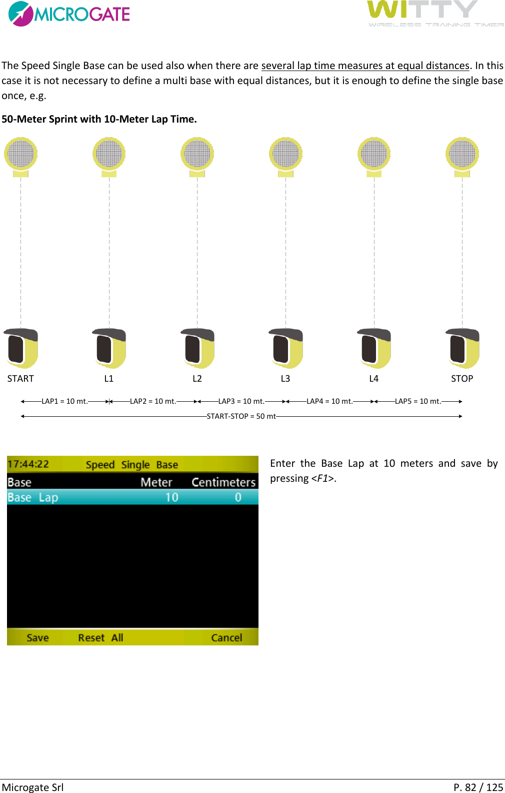
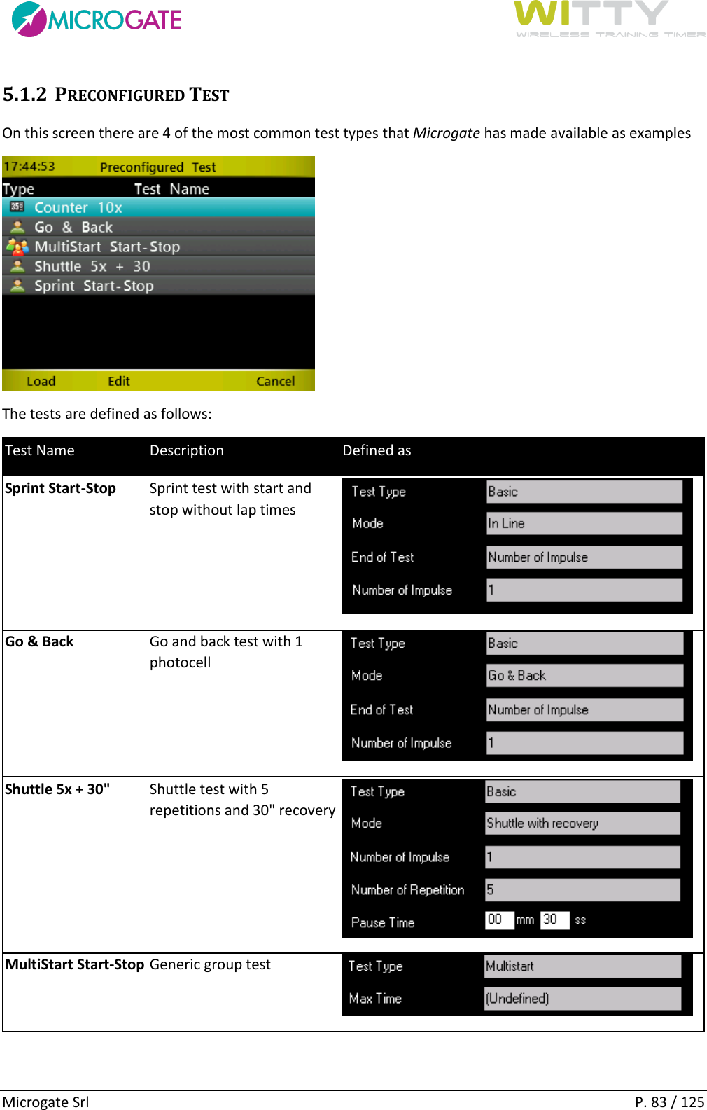
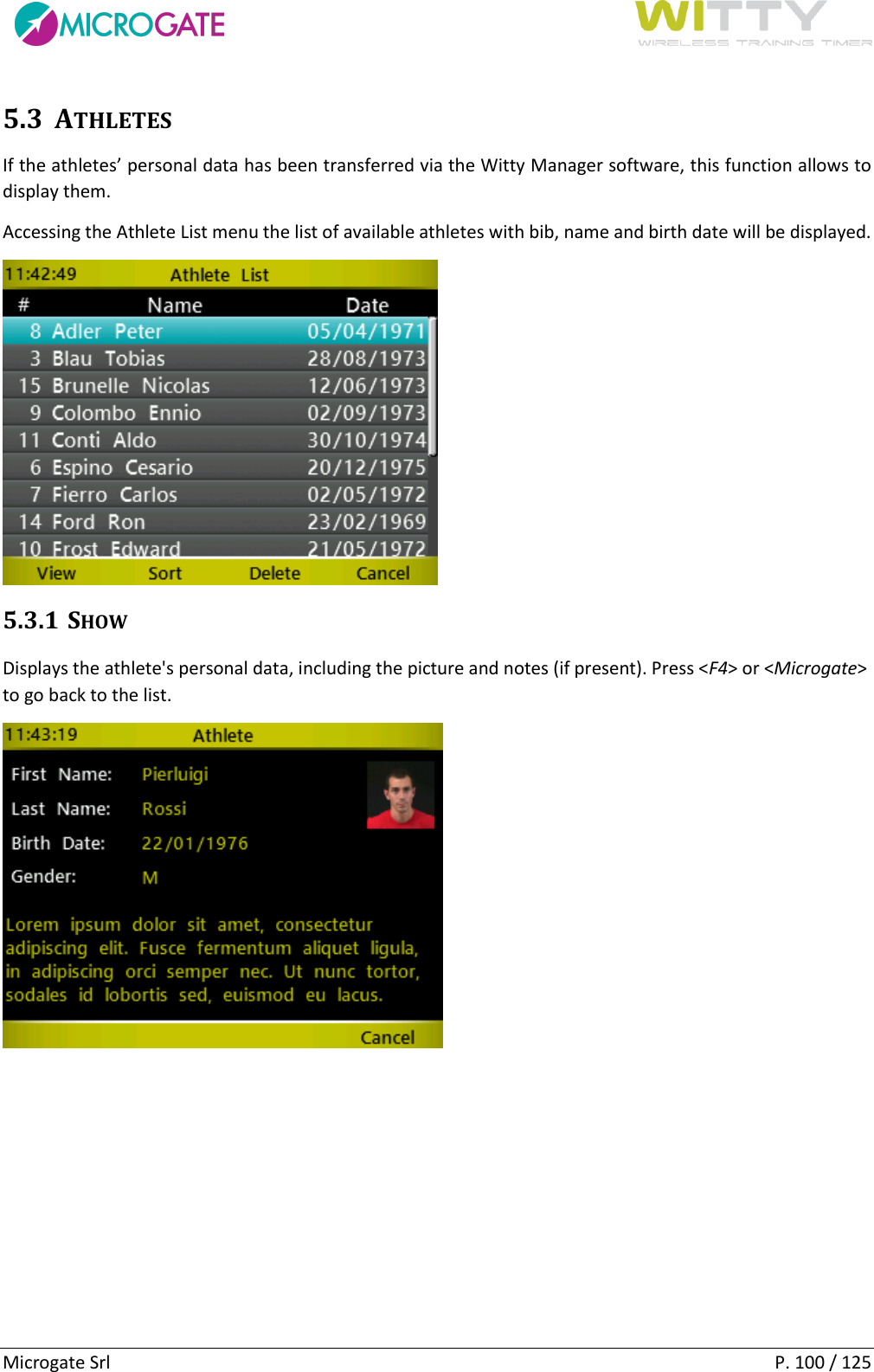
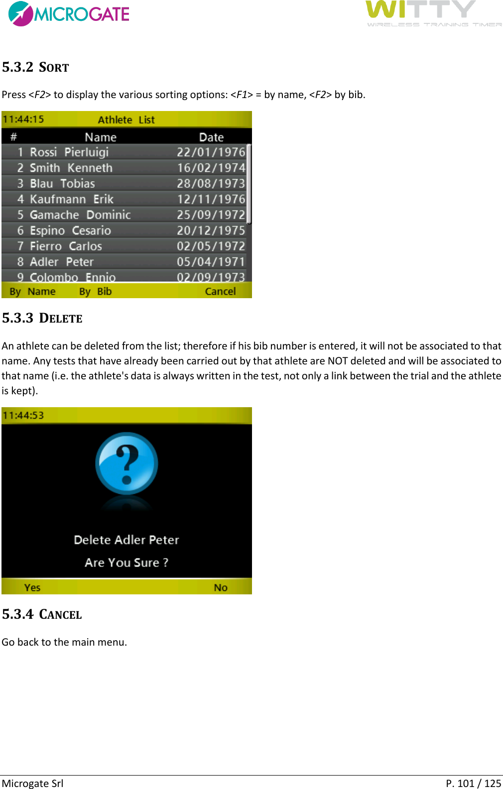
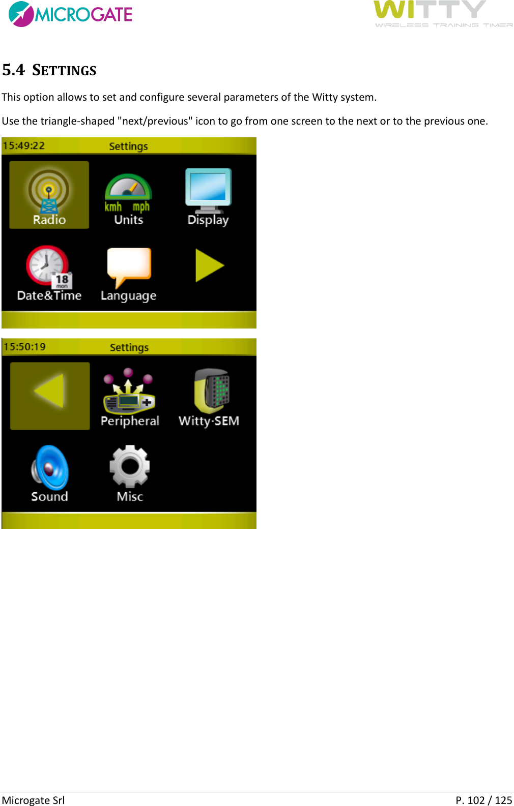
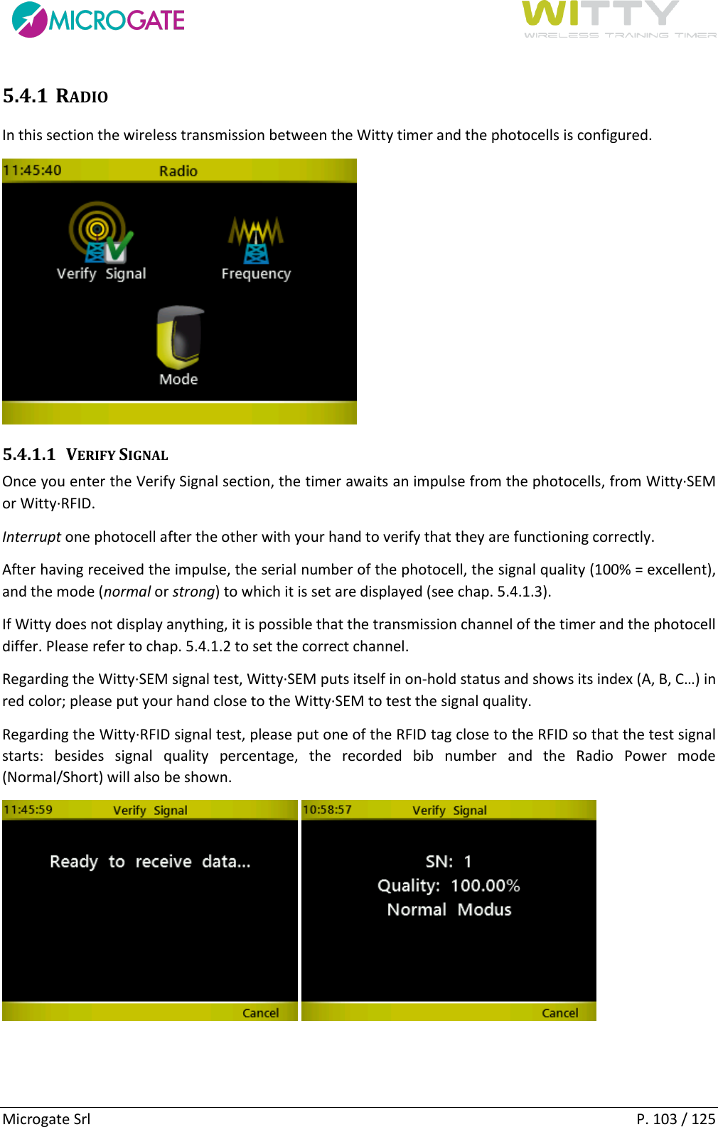
User Manual
Navigation menu
Upload a User Manual
Namespaces
Wiki Guide
HTML
PDF
Info
Views
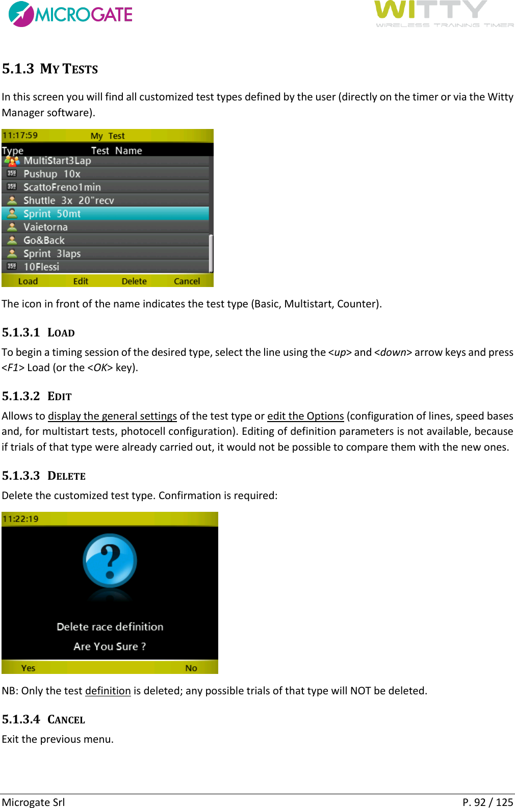
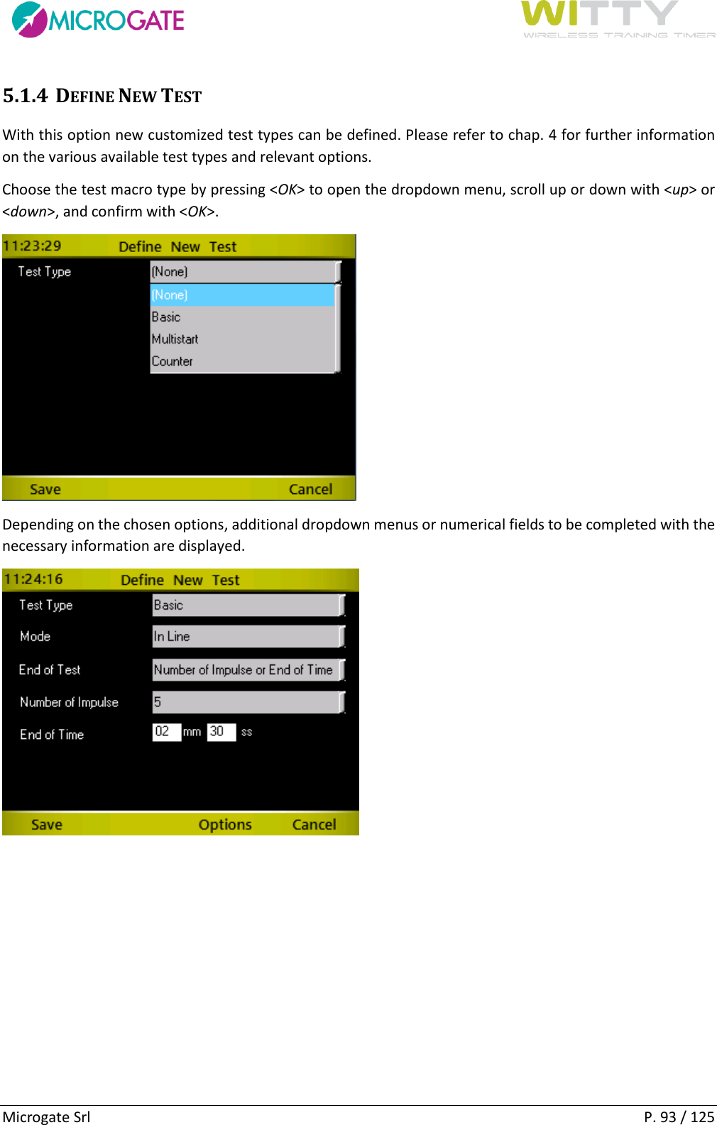
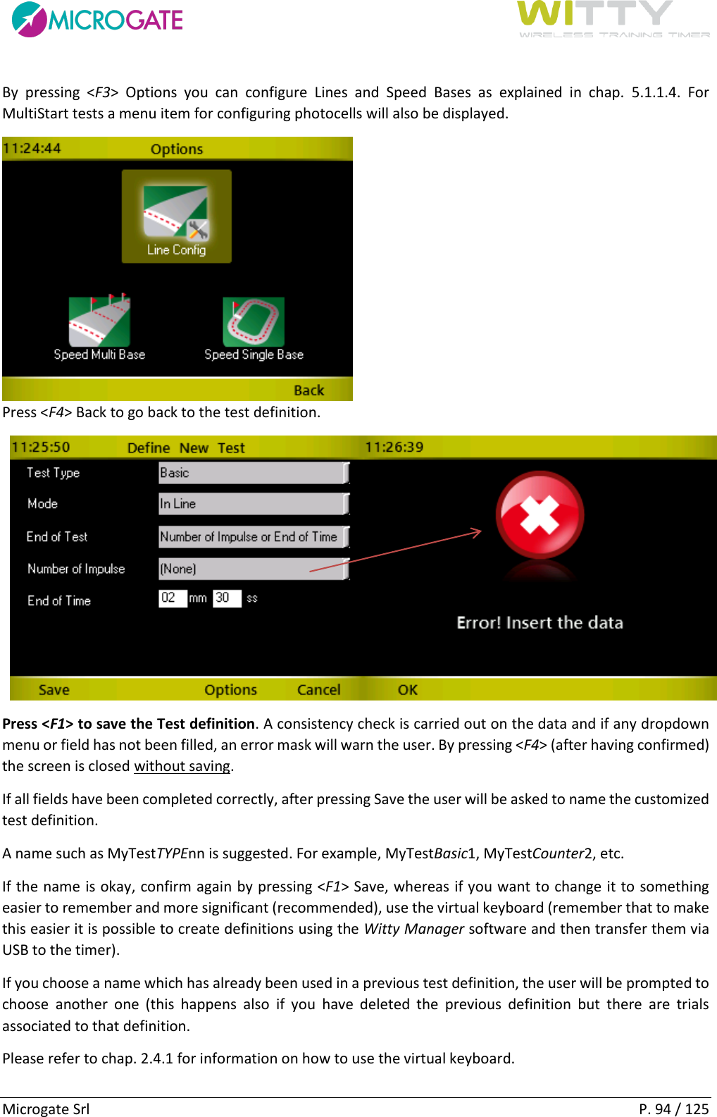
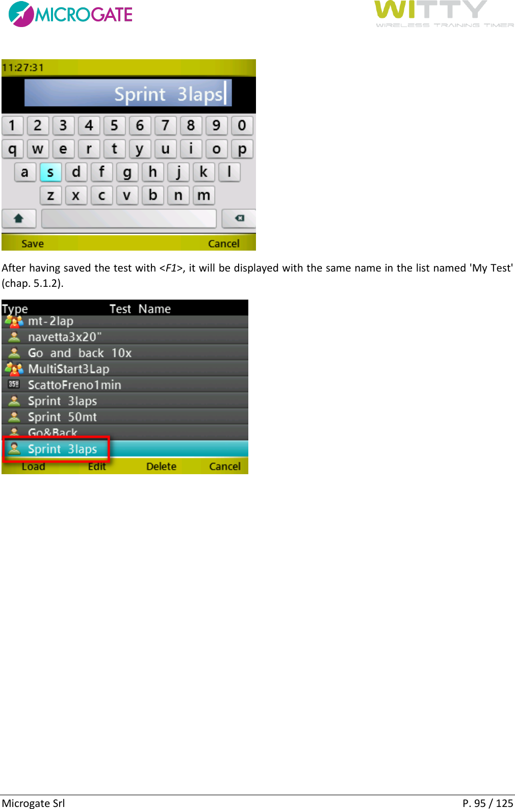
User Manual
Discussion / Help
Navigation