MediaTek RT3290 802.11b/g/n 1T1R Combo Card User Manual RT3290 Installation guide
MediaTek Inc. 802.11b/g/n 1T1R Combo Card RT3290 Installation guide
UserManual.wiki
>
MediaTek
>
RT3290 User Manual
>
User Manual.pdf
Contents
1.
User Manual
2.
User manual
3.
User Manual.pdf
4.
user manual
5.
user manual Safety guide
6.
Users Manual
7.
User Manual Regulatory Guide
8.
Users Manual Regulatory Guide
9.
Host User Manual
10.
Host User Manual Regulatory
User Manual.pdf
Navigation menu
Upload a User Manual
Namespaces
Wiki Guide
HTML
PDF
Info
Views
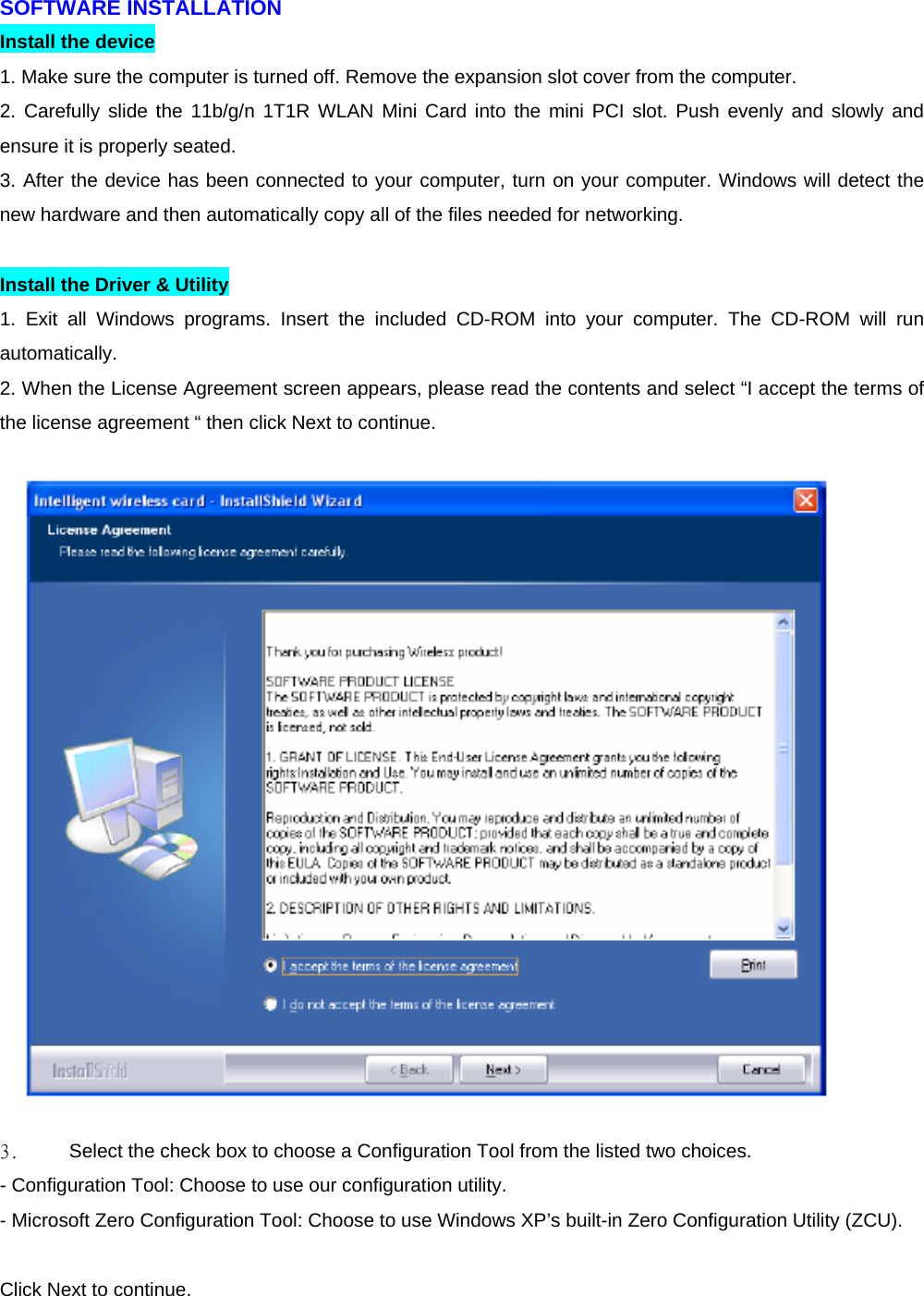
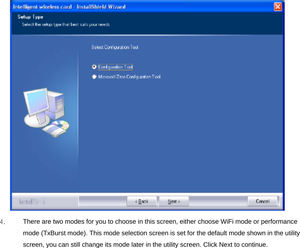
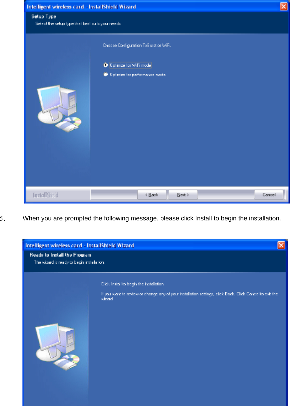
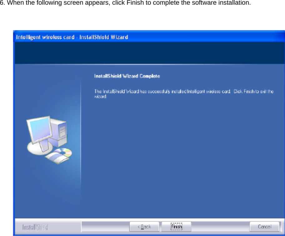
User Manual
Discussion / Help
Navigation