MaxStream 9XTEND 9XTEND OEM RF Module User Manual product manual XTend OEM RF Module v2 x4x
MaxStream Inc. 9XTEND OEM RF Module product manual XTend OEM RF Module v2 x4x
UserManual.wiki
>
MaxStream
>
9XTEND User Manual
>
User Manual
Contents
1.
USERS MANUAL
2.
User Manual
User Manual
Navigation menu
Upload a User Manual
Namespaces
Wiki Guide
HTML
PDF
Info
Views
User Manual
Discussion / Help
Navigation

![© 2010 MaxStream, Inc. 41. 9XTend OEM RF ModuleThe 9XTend OEM RF Module was engineered to provide OEMs an easy-to-use RF solution that provides reliable delivery of critical data between remote devices. The module transfers a standard asynchronous serial data stream, operates within the ISM 900 MHz frequency band and sustains up to 115.2 Kbps data throughput.Key FeaturesWorldwide AcceptanceFCC Approved (USA) Refer to Appendix A [p66] for FCC Requirements.Systems that include XTend RF Modules inherit MaxStream’s Certifications.ISM (Industrial, Scientific & Medical) license-free 902-928 MHz frequency bandManufactured under ISO 9001:2000 registered standardsESD (Electrostatic Discharge) immunity - ESD-hardened and IEC1000-4-2 (Level 4) tested9XTend OEM RF Modules are optimized for use in the US, Canada, and Australia (contact Digi for complete list of agency approvals).Long Range Data Integrity1 Watt Power Output (variable 1mW - 1W)Range (@9,600 bps throughput data rate): Indoor/Urban: up to 3000’ (900 m) Outdoor RF line-of-sight: up to 14 miles (22 km) w/dipole antenna Outdoor RF line-of-sight:up to 40 miles (64 km) w/high-gain antennaRange (@115,200 bps throughput data rate): Indoor/Urban: up to 1500’ (450 m) Outdoor RF line-of-sight:up to 7 miles (11 km) w/dipole antenna Outdoor RF line-of-sight:up to 20 miles (32 km) w/high-gain antennaContinuous RF data stream up to 115,200 bpsReceiver Sensitivity: -110 dBm (@ 9600 baud),–100 dBm (@ 115200 baud)Advanced Networking & SecurityTrue Peer-to-Peer (no Master device required),Point-to-Point, Point-to-Multipoint & MultidropRetries and AcknowledgementsFHSS (Frequency Hopping Spread Spectrum)10 hopping channels, each with over 65,000unique network addresses available256-bit AES Encryption 128-bit AES for international variantLow Power2.8 - 5.5 V Supply VoltagePin, Serial Port and Cyclicsoftware sleep modes supportedShutdown pin enables hardware sleep modethat draws only 5 μA (typical)Easy-to-UseNo configuration necessary for out-of boxRF communicationsFree X-CTU Software(Testing and configuration software)RF Modules easily configured usingstandard AT & binary commandsTransparent Operation (Wireless links replace serial wires)API Operation (Frame-based communications)Portable (small form-factor easily designed into a wide range of data systems)Software-selectable I/O interfacing ratesMultiple data formats supported(parity, start and stop bits, etc.)XII™ Interference ImmunityNo Master/Slave setup dependencies](https://usermanual.wiki/MaxStream/9XTEND.User-Manual/User-Guide-1251932-Page-4.png)
![9XTend™ OEM RF Module - Product Manual v2.x6x© 2010 MaxStream, Inc. 5Specifications* If the supply voltage for a given power se ing is lower than the minimum supply voltage requirement (as shown in Table 1-02), the TX Power Output will decrease to the highest power level se ing given the current supply voltage.** 1W Power Output is not supported when using a 3.3 supply voltage.Table 1-01. 9XTend-PKG-R OEM RF Module9XTend 900 MHz OEM RF Module SpecificationsPerformance @9600 bps Throughput Data Rate @115200 bps Throughput Data RateTransmit Power Output (software selectable using PL command) ttaW 1 - Wm1ttaW 1 - Wm1)m 054( ’0051 ot pU)m 009( ’0003 ot pUegnaR nabrU/roodnIOutdoorRF line-of-sight RangeUp to 14 miles (22 km) w/ dipole antennaUp to 40 miles (64 km) w/ high-gain antennaUp to 7 miles (11 km) w/ dipole antennaUp to 20 miles (32 km) w/ high-gain antennaInterface Data Rate(software selectable using BD command) spb 004032 – 0021spb 004032 – 0021Throughput Data Rate(software selectable using BR command) spb 002,511spb 006,9spb 000,521spb 000,01etaR ataD FRmBd 001-mBd 011-ytivitisneS revieceRPower RequirementsAm 08tnerruC evieceRlacipyt Aμ 5nwoD rewoP edoM nwodtuhSAμ 741nwoD rewoP peelS niPIdle CurrentsAm 8.0 - 3.0)8=MS( peels cilcyc ces 61Am 4.1 - 4.0)7=MS( peels cilcyc ces 8Am 6.2 - 6.0)6=MS( peels cilcyc ces 4Am 8.4 - 9.0)5=MS( peels cilcyc ces 2Am 7.8 - 6.1)4=MS( peels cilcyc ces 1Networking & SecurityFrequency 902-928 MHz)murtcepS daerpS gnippoH ycneuqerF( SSHFmurtcepS daerpS)gniyeK tfihS ycneuqerF( KSFnoitaludoMaler ”evalS/retsaM“( reeP-ot-reePseigolopoT krowteN detroppuS tionship not required), Point-to-Point, Point-to-Multipointseicneuqerf 05 erahs secneuqes poh 01yticapaC lennahC refeR – noitpyrcnE SEA tib-652noitpyrcnE to the KY Command [p29] to implementPhysical Properties x ”83.2 x ”44.1eziS draoB eludoM FR 0.20” (3.65 cm x 6.05 cm x 0.51 cm)Weight 0.64 oz. (18 g)Connector 20-pin04-erutarepmeT gnitarepO to 85º C (industrial)AntennaXCMM ro )AMS ytiralop-esreveR( AMSPRsnoitpO rotcennoCdecnalabnu smho 05ecnadepmICertifications (partial list) DNETX9-RUO742.51 traP CCFDNETX9-A4124)CI( adanaC yrtsudnITable 1-02. XTend OEM RF Module Specęcations - Relative to user-selected TX Power OutputPower Requirements (Supply voltage and TX currents relative to each TX Power Output option)Transmit Power Output 1 mW 10 mW 100 mW 500 mW * 1 W *CDV 5.5 - 57.4CDV 5.5 - 0.3CDV 5.5 - 8.2egatloV ylppuSTransmit Current (5 V) typical 110 mA 140 mA 270 mA 500 mA 730 mATransmit Current (3.3 V) typical 90 mA 110 mA 260 mA 600 mA ****** Throughput is always lower than the RF data rate due to overhead.](https://usermanual.wiki/MaxStream/9XTEND.User-Manual/User-Guide-1251932-Page-5.png)
![9XTend™ OEM RF Module - Product Manual v2.x6x© 2010 Digi Internatonal, Inc. 6Pin SignalsFigure 1-01. XTend OEM RF Module Pin Numbers * RF module has 10K : internal pull-up resistorNote: When integrating the module with a Host PC board, all lines not used should be left disconnected (floating).Table 1-03. Pin Signal Descriptions(Low-asserted signals distinguished with a horizontal line over signal name.)Pin Number Mnemonic I/O High Impedance during ShutdownMust Connect Function1GND- - yesGround2 VCC I - yes Power: 2.8 - 5.5 VDC3GPO2 / RX LED Oyes -General Purpose Output 2: <Default (CD=2)> Pin is driven low. Refer to the CD Command [p24] for other configuration options.RX LED: Pin is driven high during RF data reception; otherwise, the pin is driven low. Refer to the CD Command [p24] to enable.4 TX_PWR O yes -Transmit_Power: Pin pulses low during RF transmission; otherwise, the pin is driven high to indicate power is on and the module is not in Sleep or Shutdown Mode.5DIIyes yesData In: Serial data entering the module (from the UART host). Refer to the Serial Communications [p9] section for more information.6DOOyes -Data Out: Serial Data exiting the module (to the UART host). Refer to the Serial Communications [p9] section for more information.7 SHDN Ino yesShutdown: Pin is driven high during operation and low during Shutdown. Shutdown enables the lowest power mode (~5 μA) available to the module. Refer to the Shutdown Mode [p14] section for more information.8 GPI2 / SLEEP I yes -General Purpose Input 2: reserved for future useSLEEP: By default, SLEEP is not used. To configure this pin to enable Sleep Modes, refer to the Sleep Mode [p14], SM Command [p37] & PW Command [p32] sections.9GPO1 / CTS / RS-485 TX_EN Oyes -General Purpose Output 1: reserved for future useCTS (Clear-to-Send): <Default (CS=0)> When pin is driven low, the UART host is permitted to send serial data to the module. Refer to the Serial Communications [p9] & CS Command [p25] sections for more information.RS-485 Transmit Enable: To configure this pin to enable RS-485 half and full-duplex communications. Refer to the Serial Communications [p9] & CS Command [p25] sections.10 GPI1 / RTS / CMD Iyes -General Purpose Input 1: reserved for future useRTS (Request-to-Send): By default, is not used. To configure this pin to regulate the flow of serial data exiting the module, refer to the Serial Communications [p9] & RT Command [p36] sections.CMD (Command): By default, CMD is not used. To configure this pin to enable binary command programming, refer to the Binary Commands [p17] & RT Command [p36] sections.11 CONFIG / RSSII* no -Configuration: Pin can be used as a backup method for entering Command Mode during power-up. Refer to the Command Mode [p17] section for more information. O* no -Receive Signal Strength Indicator: By default, pin is used as an RSSI PWM output after at the conclusion of the power-up sequence. Refer to the RP Command [p35] for more information. The PWM output is 2.8V-level.tcennoc ton od / devreser02-21](https://usermanual.wiki/MaxStream/9XTEND.User-Manual/User-Guide-1251932-Page-6.png)

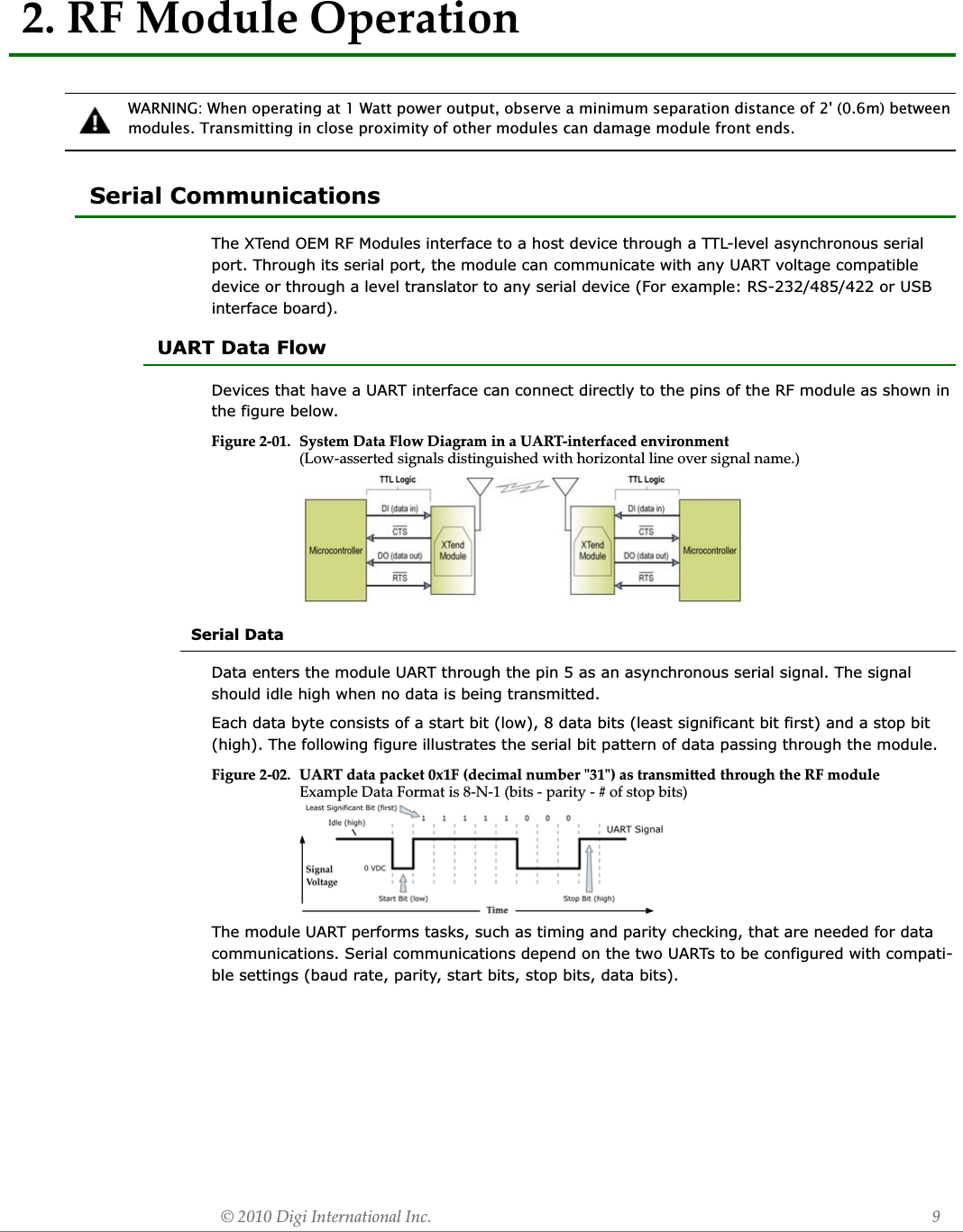
![9XTend™ OEM RF Module - Product Manual v2.x6x© 2010 Digi Internatonal, Inc. 10Flow ControlFigure 2-03. Internal Data Flow Diagram (The ęve most commonly-used pin signals shown)DI (Data In) Buffer and Flow ControlWhen serial data enters the module through the DI pin (pin 5), the data is stored in the DI Buffer until it can be processed.When the RB and RO parameter thresholds are satisfied (refer to ‘Transmit Mode’ section for more information), the module attempts to initialize an RF connection. If the module is already receiving RF data, the serial data is stored in the module's DI Buffer. The DI buffer stores at least 2.1 KB. If the DI buffer becomes full, hardware or software flow control must be implemented in order to prevent overflow (loss of data between the host and RF module).How to eliminate the need for flow control:Two cases in which the DI Buffer may become full and possibly overflow:Hardware Flow Control (CTS). When the DI buffer is 17 bytes away from being full; by default, the module de-asserts CTS (high) to signal to the host device to stop sending data [refer to FT (Flow Control Threshold) and CS (GPO1 Configuration) Commands]. CTS is re-asserted after the DI Buffer has 34 bytes of memory available.Software Flow Control (XON). XON/XOFF software flow control can be enabled using the FL (Software Flow Control) Command. This option only works with ASCII data.DO (Data Out) BufferWhen RF data is received, the data enters the DO buffer and is sent out the serial port to a host device. Once the DO Buffer reaches capacity, any additional incoming RF data is lost. The DO buffer stores at least 2.1 KB.Two cases in which the DO Buffer may become full and possibly overflow:Hardware Flow Control (RTS). If RTS is enabled for flow control (RT Parameter = 2), data will not be sent out the DO Buffer as long as RTS (pin 10) is de-asserted. Software Flow Control (XOFF). XON/XOFF software flow control can be enabled using the FL (Software Flow Control) Command. This option only works with ASCII data.1. Send messages that are smaller than the DI buffer size. The size of the DI buffer varies according to the packet size (PK parameter) and the parity setting (NB parameter) used.2. Interface at a lower baud rate (BD parameter) than the RF data rate (BR parameter).1. If the serial interface data rate is set higher than the RF data rate of the module, the mod-ule will receive data from the host faster than it can transmit the data over-the-air.2. If the module is receiving a continuous stream of RF data or if the module is monitoring data on a network, any serial data that arrives on the DI pin (pin 5) is placed in the DI Buffer. The data in the DI buffer will be transmitted over-the-air when the module no longer detects RF data in the network.1. If the RF data rate is set higher than the interface data rate of the module, the module will receive data from the transmitting module faster than it can send the data to the host.2. If the host does not allow the module to transmit data out from the DO buffer because of being held off by hardware or software flow control.](https://usermanual.wiki/MaxStream/9XTEND.User-Manual/User-Guide-1251932-Page-10.png)
![9XTend™ OEM RF Module - Product Manual v2.x6x© 2010 Digi Internatonal, Inc. 11Transparent OperationBy default, XTend RF Modules operate in Transparent Mode. The modules act as a serial line replacement - all UART data received through the DI pin is queued up for RF transmission. When RF data is received, the data is sent out the DO pin.When the RO (Packetization Timeout) parameter threshold is satisfied, the module attempts to ini-tialize an RF transmission. If the module cannot immediately transmit (for instance, if it is already receiving RF data), the serial data continues to be stored in the DI Buffer. Data is packetized and sent at any RO timeout or when the maximum packet size is received.The module operates as described above unless the Command Mode Sequence is detected. The Command Mode Sequence consists of three copies of the command sequence character [CC parameter] surrounded by the before and after guard times [BT & AT parameters].If the DI buffer becomes full, hardware or software flow control must be implemented in order to prevent overflow (loss of data between the host and module).API OperationAPI (Application Programming Interface) Operation is an alternative to the default Transparent Operation. The API is frame-based and extends the level to which a host application can interact with the networking capabilities of the module. When in API mode, all data entering and leaving the RF module is contained in frames that define operations or events within the module.Transmit Data Frames (received through the DI (Data In) pin) include: 16-bit addressReceive Data Frames (sent out the DO (Data Out) pin) include: Showing a received RF packet (16 bits only) Response to a TX (Transmit) packet Showing events such as hardware reset, watchdog reset, asynchronous events, etc.The module will send data frames to the application containing status packets; as well as source, RSSI and payload information from received data packets.API operation option facilitates many operations such as the examples cited below:To implement API operations, refer to ‘API Operation’ sections [p40].DigiMesh OperationXTend OEM RF Modules containing firmware version 8020 (or above) now feature DigiMesh mesh networking support. Mesh networking allows messages to be routed through several different 9XTend nodes to a final destination node. This firmware load allows OEMs and system integrators to bolster their networks with the self-healing attributes of mesh networking. In the event that one RF connection between nodes is lost (due to power-loss, environmental obstructions, etc.) critical data can still reach its destination due to mesh networking capabilities embedded inside the module. Transparent or API operations can be used in conjunction with the mesh networking topology. -> Change destination addresses without having to enter command mode-> Receive success/failure status of each RF packet-> Identify the source address of each received packet](https://usermanual.wiki/MaxStream/9XTEND.User-Manual/User-Guide-1251932-Page-11.png)
![9XTend™ OEM RF Module - Product Manual v2.x6x© 2010 Digi Internatonal, Inc. 12Modes of OperationXTend RF Modules operate in six modes.Figure 2-04. XTend RF Module Modes of Operation(RF modules can only be in one mode at a time)Idle ModeWhen not receiving or transmitting data, the RF module is in Idle Mode. The module shifts into the other modes of operation under the following conditions: Transmit Mode: Serial data is received in the DI Buffer Receive Mode: Valid RF data is received through the antenna Shutdown Mode: Shutdown condition is met Sleep Mode: Sleep Mode condition is met Command Mode: Command Mode Sequence is issuedThe module automatically transitions back to Idle Mode after responding to these conditions.Transmit ModeWhen the first byte of serial data is received from the UART in the DI buffer, the module attempts to shift to Transmit Mode and initiate an RF connection with other modules. After transmission is complete, the module returns to Idle Mode.RF transmission begins after either of the following criteria is met:Figure 2-05. Transmit Mode Data FlowThe character timeout trigger can be disabled by setting RO to zero. In this case, transmission will not begin until RB bytes have been received and are pending for RF transmission. The RB parameter may be set to any value between 1 and the RF packet size [refer to PK (Max RF Packet Size) parameter], inclusive. Note that transition to Trans-mit Mode cannot take place during RF reception; the RF reception must com-plete before the radio can transition into Transmit Mode.If RB or RO conditions are met, the module initializes a communications channel. Serial data in the DI buffer is grouped into RF pack-ets (up to 2048 bytes in each packet, refer to PK Command), converted to RF data and is transmit-ted over-the-air until the DI buffer is empty.1. RB bytes have been received by the UART and are pending for RF transmission.[Refer to the RB (Packetization Threshold) Command]2. At least one character has been received by the UART and is pending for RF transmission; and RO character times of silence been observed on the UART.[Refer to the RO (Packetization Timeout) Command]](https://usermanual.wiki/MaxStream/9XTEND.User-Manual/User-Guide-1251932-Page-12.png)
![9XTend™ OEM RF Module - Product Manual v2.x6x© 2010 Digi Internatonal, Inc. 13Channel initialization is the process of sending an RF initializer that synchronizes receiving mod-ules with the transmitting module. During channel initialization, incoming serial data accumulates in the DI buffer.RF data, which includes the payload data, follows the RF initializer. The payload includes up to the maximum packet size (PK Command) bytes. As the TX module nears the end of the transmission, it inspects the DI buffer to see if more data exists to be transmitted. This could be the case if more than PK bytes were originally pending in the DI buffer or if more bytes arrived from the UART after the transmission began. If more data is pending, the transmitting module assembles a subsequent packet for transmission.Refer to the ‘RF Communication Modes’ section to view state diagrams that illustrate channel ini-tialization and the sequence of events that follow.RF PacketFigure 2-06. RF Packet Components* When streaming multiple RF packets, the RF Initializer is only sent in front of the first packet.RF InitializerAn RF initializer is sent each time a new connection sequence begins. The RF initializer contains channel information that notifies receiving modules of information such as the hopping pattern used by the transmitting module. The first transmission always sends an RF initializer.An RF initializer can be of various lengths depending on the amount of time determined to be required to prepare a receiving module. For example, a wake-up initializer is a type of RF initializer used to wake remote modules from Sleep Mode (Refer to the FH, LH, HT and SM Commands for more information). The length of the wake-up initializer should be longer than the length of time remote modules are in cyclic sleep.HeaderThe header contains network addressing information that filters incoming RF data. The receiving module checks for matching a Hopping Channel, VID and Destination Address. Data that does not pass through all three network filter layers is discarded. Refer to the ‘Addressing’ section of the “RF Communication Modes” chapter for more information.CRC (Cyclic Redundancy Check)To verify data integrity and provide built-in error checking, a 16-bit CRC (Cyclic Redundancy Check) is computed for the transmitted data and attached to the end of each RF packet. On the receiving end, the receiving module computes the CRC on all incoming RF data. Received data that has an invalid CRC is discarded [refer to the ‘Receive Mode’ section].Receive ModeIf a module detects RF data while operating in Idle Mode, the module transitions to Receive Mode to start receiving RF packets. Once a packet is received, the module checks the CRC (cyclic redun-dancy check) to ensure that the data was transmitted without error. If the CRC data bits on the incoming packet are invalid, the packet is discarded. If the CRC is valid, the packet proceeds to the DO Buffer.](https://usermanual.wiki/MaxStream/9XTEND.User-Manual/User-Guide-1251932-Page-13.png)
![9XTend™ OEM RF Module - Product Manual v2.x6x© 2010 Digi Internatonal, Inc. 15In order to enter Sleep Mode, one of the following conditions must be met (in addition to the mod-ule having a non-zero SM parameter value):When in Sleep Mode, the module will not transmit or receive data until the module first transitions to Idle Mode. All Sleep Modes are enabled and disabled using SM Command. Transitions into and out of Sleep Modes are triggered by various mechanisms as shown in the table below.The SM (Sleep Mode) command is central to setting all Sleep Mode configurations. By default, Sleep Modes are disabled (SM = 0) and the module remains in Idle/Receive Mode. When in this state, the module remains constantly ready to respond to serial or RF activity.Refer to the ‘Hardware Sleep’ section of the ‘Shutdown Mode’ section [previous page] to enable the module's lowest power-consuming state (5 μA typical power-down current).Pin Sleep (SM = 1) Pin/Host-controlled Typical power-down current: < 147 μAThis mode is voltage level activated. When the SLEEP pin is asserted, the module will finish any transmitting or receiving activity; enter Idle Mode; then enter a state of sleep. When in Pin Sleep Mode, the module will not respond to serial or RF activity. After enabling Pin Sleep, the SLEEP pin controls whether the module is active or sleeping. When SLEEP is de-asserted, the module is fully operational. When SLEEP is asserted, the module transi-tions to Sleep Mode and remains in its lowest power-consuming state until the pin is de-asserted. This pin is only active if the module is setup to operate in this mode; otherwise the pin is ignored.Once in Pin Sleep, CTS (GPO1) is de-asserted (high), indicating that data should not be sent to the module. The PWR pin is also de-asserted (low) when the module is in Pin Sleep Mode.Note: The module will complete a transmission or reception before activating Pin Sleep.Serial Port Sleep (SM = 2) Wake on serial port activity Typical power-down current: < 10 mASerial Port Sleep is a Sleep Mode in which the module runs in a low power state until serial data is detected on the DI pin.1. The module is idle (no data transmission or reception) for the amount of time defined by the ST (Time before Sleep) parameter. [NOTE: ST is only active when SM = 4-5.]2. SLEEP (pin 8) is asserted (only for the ‘Pin Sleep’ option).Table 2-01. Summary of Sleep Mode CoęurationsSleep Mode (Setting)Transition into Sleep ModeTransition out of Sleep Mode (wake)RelatedCommandsPowerConsumptionPin Sleep(SM = 1)Assert (high) SLEEP pin - A micro controller can shut down and wake modules via the SLEEP pin.Note: The module will complete a transmission or reception before activating Pin Sleep.De-assert (low) SLEEP pin (SM) < 147 μASerial Port Sleep(SM = 2)Automatic transition to Sleep Mode occurs after a user-defined period of inactivity (no transmitting or receiving of data). Period of inactivity is defined by the ST (Time before Sleep) Command.When a serial byte is received on the DI pin (SM), ST < 10 mACyclic Sleep(SM = 4 - 8)RF module transitions in and out of Sleep Mode in cycles (user-selectable wake-up interval of time is set using the SM command). The cyclic sleep interval of time must be shorter than the interval of time that is defined by the LH (Wake-up Initializer TImer) command.Note: The module can be forced into Idle Mode using the SLEEP pin if the PW (Pin Wake-up) command is issued.(SM), ST, HT, LH, PW< 1.6 mA when sleeping(SM=4, 1 sec., @120K baud)](https://usermanual.wiki/MaxStream/9XTEND.User-Manual/User-Guide-1251932-Page-15.png)
![9XTend™ OEM RF Module - Product Manual v2.x6x© 2010 Digi Internatonal, Inc. 17AT Command ModeTo Enter AT Command Mode:Default AT Command Mode Sequence (for transition to Command Mode): No characters sent for one second [refer to the BT (Guard Time Before) Command] Input three plus characters (“+++”) within one second[refer to the CC (Command Sequence Character) Command.] No characters sent for one second [refer to the AT (Guard Time After) Command.]All of the parameter values in the sequence can be modified to reflect user preferences.To Send AT Commands:Figure 2-09. Syntax for sending AT Commands To read a parameter value stored in the module register, leave the parameter field blank.The preceding example would change the module’s Destination Address to "0x1F". To store the new value to non-volatile (long term) memory, the Write (ATWR) command must subsequently be sent before powering off the module.System Response. When a command is sent to the module, the module will parse and execute the command. Upon successful execution of a command, the module returns an “OK” message. If execution of a command results in an error, the module returns an “ERROR” message.To Exit AT Command Mode:For an example of programming the RF module using AT Commands and descriptions of each config-urable parameter, refer to the "RF Module Configuration" chapter [p19].Binary Command ModeSending and receiving parameter values using binary commands is the fastest way to change operating parameters of the module. Binary commands are used most often to sample signal strength [refer to DB (Received Signal Strength) parameter] and/or error counts; or to change module addresses and channels for polling systems when a quick response is necessary. Since the sending and receiving of parameter values takes place through the same serial data path as 'live' data (received RF payload), interference between the two types of data can be a concern.Common questions about using binary commands: What are the implications of asserting CMD while live data is being sent or received? 1. Send the 3-character command sequence "+++" and observe guard times before and after the command characters. [refer to ‘Default AT Command Mode Sequence’ below.] The ‘Ter-minal’ tab (or other serial communications software) of the X-CTU Software can be used to enter the sequence.[OR]2. Assert (low) the CONFIG pin and turn the power going to the module off and back on (or pulse the SHDN pin). [If the module is mounted to a Digi RS-232/485 Interface Board, the result can be achieved by pressing the configuration switch down for 2 seconds.]Send AT commands and parameters using the syntax shown below.1. If no valid AT Commands are received within the time specified by CT (Command Mode Timeout) Command, the module automatically returns to Idle Mode. [OR]2. Send ATCN (Exit Command Mode) Command.](https://usermanual.wiki/MaxStream/9XTEND.User-Manual/User-Guide-1251932-Page-17.png)
![9XTend™ OEM RF Module - Product Manual v2.x6x© 2010 Digi Internatonal, Inc. 18 After sending serial data, is there a minimum time delay before CMD can be asserted? Is a time delay required after CMD is de-asserted before payload data can be sent? How does one discern between live data and data received in response to a command? The CMD pin (pin 10) must be asserted in order to send binary commands to the module. The CMD pin can be asserted to recognize binary commands anytime during the transmission or recep-tion of data. The status of the CMD signal is only checked at the end of the stop bit as the byte is shifted into the serial port. The application does not allow control over when data is received, except by waiting for dead time between bursts of communication. If the command is sent in the middle of a stream of payload data to be transmitted, the command will essentially be executed in the order it is received. If the module is continuously receiving data, the radio will wait for a break in the received data before executing the command. The CTS signal will frame the response coming from the binary command request [refer to figure below].A minimum time delay of 100 μs (after the stop bit of the command byte has been sent) must be observed before the CMD pin can be de-asserted. The command executes after all parameters associated with the command have been sent. If all parameters are not received within 0.5 sec-onds, the module returns to Idle Mode. Note: When parameters are sent, they are two bytes long with the least significant byte sent first. Binary commands that return one parameter byte must be written with two parameter bytes.Commands can be queried for their current value by sending the command logically ORed (bit-wise) with the value 0x80 (hexadecimal) with CMD asserted. When the binary value is sent (with no parameters), the current value of the command parameter is sent back through the DO pin.Figure 2-010.Binary Command Write then ReadSignal #4 is CMDSignal #1 is the DI signal Signal #2 is the DO signal from the radioSignal #3 is CTS In this graph, a value was written to a reg-ister and then read out to verify it. While not in the middle of other received data, note that the CTS signal outlines the data response out of the module.IMPORTANT: In order for the module to recognize a binary command, the RT (GPI1 Configuration) parameter must be set to one. If binary programming is not enabled (RT parameter value is not equal to ‘1’), the module will not recognize that the CMD pin is asserted and therefore will not recognize the data as binary commands.Refer to [p19] for a binary programming example (DT command example returns two bytes).](https://usermanual.wiki/MaxStream/9XTEND.User-Manual/User-Guide-1251932-Page-18.png)
![© 2010 Digi International Inc. 193. RF Module ęProgramming ExamplesRefer to the ‘Command Mode’ section [p17] for information regarding entrance into Command Mode, sending AT commands and exiting Command Mode. Refer to the ‘X-CTU’ section [p81] of the ‘Development Guide’ for more information regarding MaxStream’s configuration software.AT CommandsTo Send AT Commands (Using the ‘Terminal’ tab of the X-CTU Software)Note: When using X-CTU Software to program a module, PC com port settings must match the baud (interface data rate), parity & stop bits parameter settings of the module. Use the 'Com Port Setup' section of the “PC Settings” tab to configure PC com port settings to match those of the module.Binary CommandsTo Send Binary Commands:Note: CTS (pin 9) is high when a command is being executed. Hardware flow control must be disabled as CTS will hold off parameter bytes.Example: Utilize the 'Terminal' tab of the X-CTU Software to change the module's DT (Destina-tion Address) parameter and save the new address to non-volatile memory. This example requires the installation of Digi’s X-CTU Software and a serial connection to a PC. Select the ‘Terminal’ tab of the X-CTU Software and enter the following command lines:Method 1 (One line per command)Send AT Command+++ATDT <Enter>ATDT1A0D <Enter>ATWR <Enter>ATCN <Enter>System ResponseOK <CR> (Enter into Command Mode){current value} <CR> (Read Destination Address)OK <CR> (Modify Destination Address)OK <CR> (Write to non-volatile memory)OK <CR> (Exit Command Mode)Method 2 (Multiple commands on one line)Send AT Command+++ATDT <Enter>ATDT1A0D,WR,CN <Enter>System ResponseOK <CR> (Enter into Command Mode){current value} <CR> (Read Destination Address)OK <CR> (Execute commands)Example: Use binary commands to change the RF module's destination address to 0x1A0D and save the new address to non-volatile memory.1. RT Command must be set to '1' in AT Command Mode to enable binary programming.2. Assert CMD (Pin 10 is driven high). (Enter Binary Command Mode)3. Send Bytes [parameter bytes must be 2 bytes long]:)dnammoC )sserddA noitanitseD( TD dneS(00 )setyb retemarap fo etyb tnacifingis tsaeL(D0 )setyb retemarap fo etyb tnacifingis tsoM(A1 )dnammoC )etirW( RW dneS(80 4. De-assert CMD (pin 10 is driven low). (Exit Binary Command Mode)Note: Do not send com-mands to the module during Ěsh program-ming (when parameters are being wriĴen to the module registry). Wait for the "OK" sys-tem response that fol-lows the ATWR command before enter-ing the next command or use Ěow control.](https://usermanual.wiki/MaxStream/9XTEND.User-Manual/User-Guide-1251932-Page-19.png)
![9XTend™ OEM RF Module - Product Manual v2.x6x© 2010 Digi Internatonal, Inc. 20Command Reference TableTable 3-01. XTend Commands (The RF modules expect numerical values in hexadecimal. Hexadecimal values are designated by a “0x” preęx. Decimal equivalents are designated by a “d” suĜx.)AT CommandBinary Command AT Command Name Parameter Range Command Category# Bytes ReturnedFactory Default%V 0x3B (59d) Board Voltage 0x2CCCA - 0x5BFFA [read-only] Diagnostics 4 ------ytiruceS & gnikrowteN--YM tes-otuA)d46( 04x0MA01gnicafretnI laireS2 - 0elbanE IPA--*02x.2v PAAT 0x05 (5d) Guard Time After 2 - (ATST-3) [x 100 msec] Command Mode Options 2 0x0A (10d)BD 0x15 (21d) Interface Data Rate 0 - 8 (standard rates)0x39 - 0x1C9C38 (non-standard rates) Serial Interfacing 4 311gnicafretnI FR1 - 0etaR ataD FR)d75( 93x0RBBT 0x04 (4d) Guard Time Before 0 - 0xFFFF [x 100 msec] Command Mode Options 2 0x0A (10d))d34( ]"+"[ B2x01snoitpO edoM dnammoCF7x0 - 02x0retcarahC ecneuqeS dnammoC)d91( 31x0CC21gnicafretnI laireS4 - 0noitarugifnoC 2OPG)d04( 82x0DC11snoitpO edoM dnammoC2 - 0esaB rebmuN--FC----snoitpO edoM dnammoC--edoM dnammoC tixE)d9( 90x0NC01gnicafretnI laireS4 - 0noitarugifnoC 1OPG)d13( F1x0SCCT 0x06 (6d) Command Mode Timeout 2 - 0xFFFF [x 100 ms] Command Mode Options 2 0xC8 (200d)DB 0x36 (54d) Received Signal Strength 0x6E - 0x28 [read-only] Diagnostics 2 --02ytiruceS & gnikrowteNFFFFx0 - 0sserddA noitanitseD)d0( 00x0TD----snoitpO edoM dnammoC--ffO ohcE)d01( A0x00E----snoitpO edoM dnammoC--nO ohcE)d11( B0x01E02scitsongaiDFFFFx0 - 0tnuoC rorrE evieceR)d51( F0x0RE----)rewoP woL( peelS--rezilaitinI pu-ekaW ecroF)d31( D0x0HF01gnicafretnI laireS1 - 0lortnoC wolF erawtfoS)d7( 70x0LFFS 0x3E (62d) Forced Sync Time 0 - 0xFFFF [x 10 msec] RF Interfacing 2 0FT 0x24 (36d) Flow Control Threshold 0 - (DI buffer size - 0x11) [Bytes] Serial Interfacing 2 DI buffer size minus 0x1102scitsongaiDFFFFx0 - 0tnuoC dooG evieceR)d61( 01x0DG01ytiruceS & gnikrowteN9 - 0lennahC gnippoH)d71( 11x0PHHT 0x03 (3d) Time before Wake-up Initializer 0 - 0xFFFF [x 100 msec] Sleep (Low Power) 2 0xFFFF (65535d)HV -- Hardware Version 0 - 0xFFFF [read-only] Diagnostics 2 --ID 0x27 (39d) Modem VID 0x11 - 0x7FFF (user-settable)0x8000 - 0xFFFF (factory-set, read-only) Networking & Security 2 0x3332 (13106d)KY 0x3C (60d) AES Encryption Key 0 - (64 hex digits all set to 'F') Networking & Security 2 0 (disabled)LH 0x0C (12d) Wake-up Initializer Timer 0 - 0xFF [x 100 msec] Sleep (Low Power) 1 101ytiruceS & gnikrowteN6 - 0edoM FR)d94( 13x0*02x.2v DM2ytiruceS & gnikrowteNFFFFx0 - 0ksaM sserddA)d81( 21x0KM 0xFFFF (65535d)MT 0x3D (61d) Multi-Transmit 0 01ytiruceS & gnikrowteNFFx0 -MY 0x2A (42d) Source Address 0 2ytiruceS & gnikrowteNFFFFx0 - 0xFFFF (65535d)01gnicafretnI laireS4 - 0ytiraP)d53( 32x0BN02ytiruceS & gnikrowteNFFFFx0 - 0sserddA nigeB gnilloP)d96( 54x0*02x.2v BPPD v2.x20* 0x47 (71d) Minimum Polling Delay 0 - 0xFFFF (Base: (x 1 ms), Remote: [x 10 ms]) Networking & Security 2 002ytiruceS & gnikrowteNFFFFx0 - 0sserddA dnE gnilloP)d07( 64x0*02x.2v EP](https://usermanual.wiki/MaxStream/9XTEND.User-Manual/User-Guide-1251932-Page-20.png)
![9XTend™ OEM RF Module - Product Manual v2.x6x© 2010 Digi Internatonal, Inc. 21* Firmware version in which command and parameter options were ęrst supportedPK 0x29 (41d) Maximum RF Packet Size 1 - 0x800 [Bytes] RF Interfacing 2 varies)ttaW 1( 41gnicafretnI FR4 - 0leveL rewoP XT)d85( A3x0LP01)rewoP woL( peelS1 - 0pu-ekaW niP)d92( D1x0WPRB 0x20 (32d) Packetization Threshold 1 - Current value of PK Serial Interfacing 2 0x800 (2048d)RC -- Ambient Power - Single Channel 0 - 0x31 [dBm, read-only] Diagnostics 1 ------)laicepS(--stluafeD erotseR)d41( E0x0ERRM -- Ambient Power - All Channels No parameter - 0x7D0 Diagnostics 2--01ytiruceS & gnikrowteN]stols[ FFx0 - 0stolS yaleD)d52( 91x0NRRO 0x21 (33d) Packetization Timeout 0 - 0xFFFF [x UART character time] Serial Interfacing 2 3RP 0x22 (34d) RSSI PWM Timer 0 - 0xFF [x 100 msec] Diagnostics 1 0x20 (32d))d01( A0x01ytiruceS & gnikrowteNFFx0 - 0seirteR)d42( 81x0 RR01gnicafretnI laireS2 - 0noitarugifnoC 1IPG)d22( 61x0TR01gnicafretnI laireS1 - 0stiB potS)d55( 73x0BSSH 0x25 (37d) Serial Number High 0 - 0xFFFF [read-only] Diagnostics 2 variesSL 0x26 (38d) Serial Number Low 0 - 0xFFFF [read-only] Diagnostics 2 variesSM 0x01 (1d) Sleep Mode 0 - 8 (3 is reserved) Sleep (Low Power) 1 0ST 0x02 (2d) Time before Sleep (ATAT+3) - 0x7FFF [x 100 msec] Sleep (Low Power) 2 0x64 (100d)TP 0x38 (56d) Board Temperature 0 - 0x7F [read-only] Diagnostics 1 --TR 0x1B (27d) Delivery Failure Count 0 - 0xFFFF [read-only] Diagnostics 2 0TT 0x1A (26d) Streaming Limit 0 - 0xFFFF [0 = disabled] Networking & Security 2 001gnicafretnI FR1 - 0ylnO timsnarT)d36( F3x0XT----scitsongaiDgnirts snruteResobrev - noisreV erawmriF--LVVR 0x14 (20d) Firmware Version 0 - 0xFFFF [read-only] Diagnostics 2 ------scitsongaiDgnirts snruteRsrebmuN gninraW evitcA--AW----scitsongaiDgnirts snruteRataD gninraW--NW----)laicepS(--etirW)d8( 80x0RW----scitsongaiDgnirts snruteRsrebmuN gninraW ykcitS--SWTable 3-01. XTend Commands (The RF modules expect numerical values in hexadecimal. Hexadecimal values are designated by a “0x” preęx. Decimal equivalents are designated by a “d” suĜx.)AT CommandBinary Command AT Command Name Parameter Range Command Category# Bytes ReturnedFactory Default](https://usermanual.wiki/MaxStream/9XTEND.User-Manual/User-Guide-1251932-Page-21.png)
![9XTend™ OEM RF Module - Product Manual v2.x6x© 2010 Digi Internatonal, Inc. 22Command DescriptionsCommands in this section are listed alphabetically. Command categories are designated between the "< >" symbols that follow each command title. By default, XTend RF Modules expect numerical values in hexadecimal since the default value of the CF (Number Base) Parameter is '1'. Hexadec-imal values are designated by the "0x" prefix and decimal values by the "d" suffix.%V (Board Voltage) Command<Diagnostics> %V Command is used to read the current voltage of the module circuit board.Sample Output:5.02 V (when ATCF = 0)5051F (when ATCF = 1) *5.02 (when ATCF = 2)* When CF = 1 (default), a hex integer is shown that is equal to (voltage * 65536d).AM (Auto-set MY) Command<Networking & Security> AM Command is used to automatically set the MY (Source Address) parameter from the factory-set serial number of the module. The address is formed with bits 29, 28 and 13-0 of the serial number (in that order). The resulting value is displayed as a result of this command.AP (API Enable) Command<Serial Interfacing> The AP command is used to enable the module to operate using the frame-based API operation.AT (Guard Time After) Command<Command Mode Options> AT Command is used to set/read the time-of-silence that follows the command sequence character (CC Command) of the AT Command Mode Sequence (BT + CC + AT). By default, 1 second must elapse before and after the command sequence character. The times-of-silence surrounding the command sequence character are used to prevent inadvert-ent entrance into AT Command Mode.Refer to the ‘AT Command Mode’ section [p17] for more information regarding the AT Command Mode Sequence.AT Command: AT%VBinary Command: 0x3B (59 decimal)Parameter Range (read-only): 0x2CCCA - 0x5BFFA (2.80 - 5.75 decimal)Number of bytes returned: 4AT Command: ATAMBinary Command: 0x40 (64 decimal)AT Command: ATAPParameter Range:0 - 2Parameter Configuration0API Disabled(Transparent Operation)1API enabled(w/out escaped characters)2API enabled (with escaped characters)Default Parameter Value:0Number of Bytes Returned:1Minimum Firmware Version Required: 2.x20AT Command: ATATBinary Command: 0x05 (5 decimal)Parameter Range:2 - (ATST-3), up to 0x7FFC[x 100 milliseconds]Default Parameter Value: 0x0A (10 decimal)Number of bytes returned: 2Related Commands: BT (Guard Time Before), CC (Command Sequence Character)](https://usermanual.wiki/MaxStream/9XTEND.User-Manual/User-Guide-1251932-Page-22.png)
![9XTend™ OEM RF Module - Product Manual v2.x6x© 2010 Digi Internatonal, Inc. 24BT (Guard Time Before) Command<AT Command Mode Options> The CC command is used to set/read the ASCII character used between guard times of the AT Command Mode Sequence (BT + CC + AT). This sequence enters the module into AT Command Mode so that data entering the module (from the host) is recognized as commands instead of payload.Refer to the ‘AT Command Mode’ section [p17] for more information regarding the AT Command Mode Sequence.CC (Command Sequence Character) Command<AT Command Mode Options> The CC command is used to set/read the ASCII character used between guard times of the AT Command Mode Sequence (BT + CC + AT). This sequence enters the module into AT Command Mode so that data entering the module (from the host) is recognized as commands instead of payload.Refer to the ‘AT Command Mode’ section [p17] for more information regarding the AT Command Mode Sequence.CD (GPO2 Configuration) Command<Serial Interfacing> CD Command is used to select/read the behavior of the GPO2 line (pin 3).CF (Number Base) Command<Command Mode Options> CF command is used to set/read the command formatting setting. The following commands are always entered and read in hex, no matter the CF setting: VR (Firmware Version)HV (Hardware Version)KY (AES Encryption Key)AT Command: ATCCBinary Command: 0x13 (19 decimal)Parameter Range: 0x20 - 0x7FDefault Parameter Value: 0x2B (ASCII “+”)Number of bytes returned: 1Related Commands: AT (Guard Time After), BT (Guard Time Before)AT Command: ATCCBinary Command: 0x13 (19 decimal)Parameter Range: 0x20 - 0x7FDefault Parameter Value: 0x2B (ASCII “+”)Number of bytes returned: 1Related Commands: AT (Guard Time After), BT (Guard Time Before)AT Command: ATCDBinary Command: 0x28 (40 decimal)Parameter Range: 0 - 8 (standard rates)Parameter Configuration0 RX LED1 Default High2 Default Low3 (reserved)4RX LED(valid address only)Default Parameter Value: 2Number of bytes returned: 1AT Command: ATCFParameter Range: 0 – 2Parameter Configuration0Commands utilize default number base; decimal commands may output units1All commands forced to unsigned, unit-less hex2Commands utilize their default number base; no units are outputDefault Parameter Value: 1Number of bytes returned: 1](https://usermanual.wiki/MaxStream/9XTEND.User-Manual/User-Guide-1251932-Page-24.png)
![9XTend™ OEM RF Module - Product Manual v2.x6x© 2010 Digi Internatonal, Inc. 25CN (Exit AT Command Mode) Command<Command Mode Options> The CN command is used to explicitly exit the module from AT Com-mand Mode.CS (GPO1 Configuration) Command<Serial Interfacing> CS Command is used to select the behavior of the GP01 pin (pin 9). This output can provide RS-232 flow control, control the TX enable signal (for RS-485 or RS-422 oper-ations). By default, GP01 provides RS-232 CTS (Clear-to-Send) flow control.CT (Command Mode Timeout) Command<Command Mode Options> The CT command is used to set and read the amount of inactive time that elapses before the module automatically exits from AT Command Mode and returns to Idle Mode.Use the CN (Exit AT Command Mode) command to exit AT Command Mode manually.DB (Received Signal Strength) Command<Diagnostics> DB Command is used to read the receive signal strength (in decibels relative to mil-liWatts) of the last received packet. This parame-ter is useful in determining range characteristics of the RF modules under various conditions. In default mode, this command shows the power level in signed decimal format with the units (dBm). If CF = 1, the magnitude of the value is pre-sented in unsigned hex. If CF = 2, the value is presented in decimal, but without the units.Sample Output:-88 dBm(when ATCF = 0)58 (when ATCF = 1)-88 (when ATCF = 2)NOTE: If the DB register is read before the module has received an RF packet, the module will return a value of 0x8000 (which means an RF packet has not yet been received).AT Command: ATCNBinary Command: 0x09 (9 decimal)AT Command: ATCSBinary Command: 0x1F (31 decimal)Parameter Range: 0 - 4Parameter Configuration0 RS-232 CTS flow control1 RS-485 TX enable low2High3 RS-485 TX enable high4LowDefault Parameter Value: 0Number of bytes returned: 1Related Commands: RT (GPI1 Configuration), TO (GP01 Timeout)AT Command: ATCTBinary Command: 0x06 (6 decimal)Parameter Range:2 - 0xFFFF [x 100 milliseconds]Default Parameter Value: 0xC8 (200d)Number of bytes returned: 2Related Command: CN (Exit AT Command Mode)AT Command: ATDBBinary Command: 0x36 (54 decimal)Parameter Range (read-only): 0x6E - 0x28(-110 to -40 Decimal)Number of bytes returned: 2](https://usermanual.wiki/MaxStream/9XTEND.User-Manual/User-Guide-1251932-Page-25.png)
![9XTend™ OEM RF Module - Product Manual v2.x6x© 2010 Digi Internatonal, Inc. 26DT (Destination Address) Command<Networking & Security> DT Command is used to set/read the networking address of an RF module. The modules utilize three filtration layers: Vendor ID Number (ATID), Channel (ATHP), and Destina-tion Address (ATDT). The DT command assigns an address to a radio that enables it to communicate with other radios in the network. The simplest use of this command is that when MY=0xFFFF and MK=0xFFFF on all radios in a network, only radios with matching DT's will communicate with each other.If MY is not 0xFFFF, then DT acts as a transmit address and MY acts as a receive address. For example, MY can be set to unique values 1, 2, 3, etc. on unique radios in the network. Then set DT on the transmitting radio to match the MY of the receiving radio you intend to communicate with.Setting DT=0xFFFF will broadcast to all radios in the network. Refer to the 'Addressing' section [p45] for more information.E0 (Echo Off) Command<Command Mode Options> E0 Command turns off character echo in AT Command Mode. By default, echo is off.E1 (Echo On) Command<Command Mode Options> E1 Command enables character echo in AT Command Mode. Each typed character will be echoed back to the terminal when ATE1 is active. E0 (Echo Off) is the default.ER (Receive Error Count) Command<Diagnostics> The ER command is used to set/read the number of receive-errors. The error count records the number of packets partially received then aborted on a reception error. This value returns to 0 after a reset and is not non-volatile (Value does not persist in the module's memory after a power-up sequence). Once the Receive Error Count reaches its maximum value (up to 0xFFFF), it remains at its maximum count value until the maximum count value is explicitly changed or the module is reset.The ER parameter is not reset by pin, serial port or cyclic sleep modes.FH (Force Wake-up Initializer) Command<Sleep (Low Power)> The FH command is used to force a Wake-up Initializer to be sent on the next transmission. Use only with cyclic sleep modes active on remote modules. ATFH will not send a long header if ATHT = 0xFFFF. WR (Write) Command does not need to be issued with FH Command.AT Command: ATDTBinary Command: 0x00Parameter Range:0 - 0xFFFFDefault Parameter Value: 0Number of bytes returned: 2Related Commands: HP (Hopping Channel), ID (Modem VID), MK (Address Mask), MY (Source Address)AT Command: ATE0Binary Command: 0x0A (10 decimal)AT Command: ATE1Binary Command: 0x0B (11 decimal)AT Command: ATERBinary Command: 0x0F (15 decimal)Parameter Range: 0 - 0xFFFFDefault Parameter Value: 0Number of bytes returned: 2Related Commands: GD (Receive Good Count)AT Command: ATFHBinary Command: 0x0D (13 decimal)](https://usermanual.wiki/MaxStream/9XTEND.User-Manual/User-Guide-1251932-Page-26.png)
![9XTend™ OEM RF Module - Product Manual v2.x6x© 2010 Digi Internatonal, Inc. 27FL (Software Flow Control) Command<Serial Interfacing> The FL command is used to configure software flow control. Hardware flow control is implemented with the module as the GP01 pin (CTS pin of the OEM RF module), which regulates when serial data can be transferred to the module. FL Command can be used to allow software flow control to also be enabled. The XON character used is 0x11 (17 decimal). The XOFF character used is 0x13 (19 decimal)FS (Forced Synch Time) Command<RF Interfacing> The FS command only applies to streaming data. Normally, only the first packet of a continuous stream contains the full RF initial-izer. The RF modules then remain synchronized for subsequent packets of the stream. This parameter can be used to periodically force an RF initializer during such streaming. Any break in UART character reception long enough to drain the DI Buffer (UART receive buffer) and cause a pause in RF data transmission will also cause an RF initializer to be inserted on the next transmission.FT (Flow Control Threshold) Command<Serial Interfacing> The FT command is used to set/read the flow control threshold. When FT bytes have accumulated in the DI buffer (UART Receive), CTS is de-asserted or the XOFF soft-ware flow control character is transmitted.GD (Receive Good Count) Command<Diagnostics> The GD command is used to set/read the count of good received RF packets. Its parameter value is reset to 0 after every reset and is not non-volatile (The parameter value does not persist in the RF module's memory after a power-up sequence). Once the "Receive Good Count" reaches its maximum value (up to 0xFFFF), it remains at its maximum count value until the maximum count value is manually changed or the module is reset.The GD parameter is not reset by pin, serial port or cyclic sleep modes.AT Command: ATFLBinary Command: 0x07 (7 decimal)Parameter Range: 0 - 1Parameter Configuration0Disable softwareflow control1Enable softwareflow controlDefault Parameter Value: 0Number of bytes returned: 1AT Command: ATFSBinary Command: 0x3E (62 decimal)Parameter Range:0 - 0xFFFF [x 10 milliseconds]Default Parameter Value: 0Number of bytes returned: 2AT Command: ATFTBinary Command: 0x24 (36 decimal)Parameter Range:0 - (DI buffer size minus 0x11) [Bytes]Default Parameter Value: DI Buffer size minus 0x11 (17 decimal)Number of bytes returned: 2AT Command: ATGDBinary Command: 0x10 (16 decimal)Parameter Range: 0 - 0xFFFFDefault Parameter Value: 0Number of bytes returned: 2Related Commands: ER (Receive Error Count)](https://usermanual.wiki/MaxStream/9XTEND.User-Manual/User-Guide-1251932-Page-27.png)
![9XTend™ OEM RF Module - Product Manual v2.x6x© 2010 Digi Internatonal, Inc. 28HP (Hopping Channel) Command<Networking & Security> The HP command is used to set/read the RF module's hopping channel number. A channel is one of three layers of filtra-tion available to the module. In order for modules to communicate with each other, the modules must have the same channel number since each channel uses a different hop-ping sequence. Different channels can be used to prevent modules in one network from listening to transmissions of another.HT (Time before Wake-up Initializer) Command<Sleep (Low Power)> The HT command is used to set/read the time of inactivity (no serial or RF data is sent or received) before a wake-up initial-izer is sent by a TX (transmitting) RF module. The HT parameter should be set shorter than inactiv-ity timeout [ST Command] time of any RX (receiving) modules operating in Cyclic Sleep (SM=4-8). The wake-up initializer sent by the TX module instructs all RX modules to remain awake to receive RF data. From the RX module perspective: After HT time elapses and the inactivity timeout [ST Command] is met, the RX module goes into cyclic sleep. In cyclic sleep, the RX module wakes once per sleep interval [SM Command] to check for a wake-up initializer. When a wake-up initializer is detected, the module stays awake to receive data. The wake-up initializer must be longer than the cyclic sleep interval to ensure that sleeping modules detect incoming data. When HT time elapses, the TX module knows it needs to send a wake-up Initializer for all RX mod-ules to remain awake and receive the next transmission.HV (Hardware Version) Command<Diagnostics> The HV command is used to read the hardware version of the RF module.ID (Modem VID) Command<Networking & Security> The ID command is used to set/read the VID (Vendor Identification Number) of the RF module. RF modules must have matching VIDs in order to communicate.AT Command: ATHPBinary Command: 0x11 (17 decimal)Parameter Range: 0 - 9Default Parameter Value: 0Number of bytes returned: 1Related Commands: ID (Modem VID), DT (Destination Address), MK (Address Mask)AT Command: ATHTBinary Command: 0x03 (3 decimal)Parameter Range:0 - 0xFFFF [x 100 milliseconds]Default Parameter Value: 0xFFFF (wake-up initializer will not be sent)Number of bytes returned: 2Related Commands: LH (Wake-up Initializer Timer), SM (Sleep Mode), ST (Time before Sleep)AT Command: ATHVParameter Range:0 - 0xFFFF [Read-only]Minimum Firmware Version Required: v1.x80AT Command: ATIDBinary Command: 0x27 (39 decimal)Parameter Range: 0x11 - 0x7FFF (user-settable) 0 - 0x10 & 0x8000 - 0xFFFF (factory-set)Default Parameter Value: 0x3332 (13106d)Number of bytes returned: 2](https://usermanual.wiki/MaxStream/9XTEND.User-Manual/User-Guide-1251932-Page-28.png)
![9XTend™ OEM RF Module - Product Manual v2.x6x© 2010 Digi Internatonal, Inc. 29KY (AES Encryption Key) Command<Networking & Security> The KY command is used to set the 256-bit AES (Advanced Encryption Standard) key for encrypting/decrypting data. Once set, the key cannot be read out of the mod-ule by any means. The entire payload of the packet is encrypted using the key and the CRC is computed across the ciphertext. When encryption is enabled, each packet carries an additional 16 bytes to convey the random CBC Initialization Vector (IV) to the receiver(s). The KY value may be “0” or any 256-bit value (= 64 hex digits = 32 bytes). Any other value, including entering ATKY by itself with no parameters, causes an error.A module with the wrong key (or no key) will receive encrypted data, but the data driven out the serial port will be meaningless. Likewise, a module with a key will receive unencrypted data sent from a module without a key, but the output will be meaningless. Because CBC mode is utilized, repetitive data appears differently in different transmissions due to the randomly-generated IV.NOTE: For international (non-U.S.) variants of 9XTend modules, the encryption key is 128-bit AES. The command operates the same except the key length is 16 bytes rather than 32 bytes. This pertains to part numbers ending with -NA or -128 (the -NA and -128 suffix mean the same thing), no matter what firmware version is loaded. This also pertains to the Australia version of firmware 22xx, no matter what part number 9XTend it is loaded onto.LH (Wake-up Initializer Timer) Command<Sleep (Low Power)> The LH Command is used to set/read the duration of time during which the wake-up initializer is sent. When receiving mod-ules are in Cyclic Sleep Mode, they power-down after a period of inactivity (as specified by the ST parameter) and will periodically wake and listen for transmitted data. In order for the receiving modules to remain awake, they must detect ~35ms of the wake-up initializer.LH Command must be used whenever a receiving module is operating in Cyclic Sleep Mode. The Wake-up Initializer Time must be longer than the cyclic sleep time that [as determined by SM (Sleep Mode) parameter]. If the wake-up initializer time were less than the Cyclic Sleep interval, the connection would be at risk of missing the wake-up initializer transmission.Refer to figures loated under the SM command description to view diagrams of correct and incor-rect configurations. The images emphasize that the LH value must be greater than the SM value.AT Command: ATKYBinary Command: 0x3C (60 decimal)Parameter Range: 0 - (64 hex digits all set to 'F')Default Parameter Value: 0 (disabled)Number of bytes returned: 2Number Base: Always HexadecimalAT Command: ATLHBinary Command: 0x0C (12 decimal)Parameter Range:0 - 0xFF [x 100 milliseconds]Default Parameter Value: 1Number of bytes returned: 1Related Commands: HT (Time before Wake-up Initializer), SM (Sleep Mode), ST (Time before Sleep)](https://usermanual.wiki/MaxStream/9XTEND.User-Manual/User-Guide-1251932-Page-29.png)
![9XTend™ OEM RF Module - Product Manual v2.x6x© 2010 Digi Internatonal, Inc. 30MD (RF Mode) Command<Networking & Security> The MD command is used to select/read the settings that enable the Polling and Repeater Modes on the module.Polling Mode - A ‘Polling Base’ is responsible for polling remotes. A ‘Polling Remote’ requires a poll in order to transmit. Repeater Mode - A ‘Repeater’ re-sends RF data unless the transmission is addressed to it or if the transmission has already been detected. A ‘Repeater End Node’ handles repeated messages, but will not repeat the message over-the-air.Refer to the Polling and Repeater Mode sections of the ‘RF Communication Modes’ chapter for more information.MK (Address Mask) Command<Networking & Security> The MK command is used to set/read the Address Mask of a module. All RF data packets contain the Destination Address of the TX (transmitting) module. When a packet is received, the TX module Destination Address is logically "ANDed" (bitwise) with the Address Mask of the RX (receiving) module. The resulting value must match the Destination Address or Address Mask of the RX module for the packet to be received and sent out the RX mod-ule's DO (Data Out) pin. If the "ANDed" value does not match the Destination Address or Address Mask of the RX module, the packet is discarded.Sniffer Mode (when MK = 0): ACK requests are ignored and every RX (receive) frame is sent to the UART, without regard for repeated frames.All “0” values are treated as irrelevant values and ignored.Refer to the ‘Addressing’ section [p45] for more information.MT (Multi-transmit) Command<Networking & Security> The MT command is used to enabled multiple transmissions of RF data packets. When Multi-transmit Mode is enabled (MT > 0), packets do not request an ACK (acknowledgement) from the receiving RF mod-ule(s). MT takes precedence over RR, so if both MT and RR are non-zero, then MT+1 packets will be sent (with no ACK requests). When a receiving module receives a packet with remaining forced retransmissions, it calculates the length of the packet and inhibits transmission for the amount of time required for all retransmissions. Thereafter, a random number of delay slots are inserted between 0 and RN before transmission is allowed from the receiving module(s). This prevents all listening modules from transmitting at once upon conclusion of a multiple trans-mission event (when RN > 0).NOTE: The actual number of forced transmissions is the parameter value plus one. For example, if MT = 1, two transmissions of each packet will be sent.AT Command: ATMDBinary Command: 0x31 (49 decimal)Parameter Range: 0 - 6Parameter Configuration0 Transparent Operation(Repeater Base)1 [reserved - not used]2[reserved - not used]3Polling Base4 Polling Remote5 Repeater6 Repeater End NodeDefault Parameter Value: 0Number of bytes returned: 1Minimum Firmware Version Required: 2.x20AT Command: ATMKBinary Command: 0x12 (18 decimal)Parameter Range:0 - 0xFFFFDefault Parameter Value: 0xFFFF (65535d)Number of bytes returned: 2Related Commands: DT (Destination Address), HP (Hopping Channel), ID (Modem VID), MY (Source Address)AT Command: ATMTBinary Command: 0x3D (61 decimal)Parameter Range: 0 - 0xFFDefault Parameter Value:0 (no forced retransmissions)Number of bytes returned: 1Related Commands: Networking (DT, MK, MY, RN, TT), Serial Interfacing (BR, PK, RB, RO), RF Interfacing (FS)](https://usermanual.wiki/MaxStream/9XTEND.User-Manual/User-Guide-1251932-Page-30.png)
![9XTend™ OEM RF Module - Product Manual v2.x6x© 2010 Digi Internatonal, Inc. 31Refer to the ‘Multi-transmit Mode’ section [p46] for more information.MY (Source Address) Command<Networking & Security> The MY command is used to set/read the Source Address of the RF module.Refer to the DT command and the 'Addressing' section [p45] for more information.NB (Parity) Command<Serial Interfacing> The NB command is used to select/read the parity settings of the RF module for UART communications.PB (Polling Begin Address) Command<Networking & Security> PB command is used to set/read the module’s Polling Begin Address - the first address polled Polling Mode is enabled.Polling Operations: The ‘Polling Base’ (MD = 3) cycles through a sequential range of addresses, polling each ‘Polling Remote’ (MD = 4). The base then waits for a response & proceeds to the next ‘Polling Remote’. Each ‘Polling Remote’ responds by sending the data from the Data In buffer fol-lowing the RB & RO parameters. When there is no eligible data to send, the ‘Polling Remote’ will not respond. The ‘Polling Base’ will move to the next address in the polling sequence after a short delay.PD (Minimum Polling Delay) Command<Networking & Security> The PD command is used to set/read Polling Delay (Base, MD=3) or Polling Timeout (Remote, MD=4). Polling Delay (Base) is the time between polling cycles. The Polling Base will start the polling cycle after sending the first poll. After the polling cycle has completed, the timer is restarted.Polling Timeout (Remote) is the amount of time the remote unit will hold data from the serial port before discarding it. Data entered within the PD time of the poll is transmitted and not discarded.AT Command: ATMYBinary Command: 0x2A (42 decimal)Parameter Range: 0 - 0xFFFFDefault Parameter Value: 0xFFFF (Disabled - DT (Destination Address) parameter serves as both source and destination address.)Number of bytes returned: 2Related Commands: DT (Destination Address), HP (Hopping Channel), ID (Modem VID), MK (Address Mask)AT Command: ATNBBinary Command: 0x23 (35 decimal)Parameter Range: 0 - 4Parameter Configuration08-bit (no parity or7-bit (any parity)18-bit even2 8-bit odd38-bit mark4 8-bit spaceDefault Parameter Value: 0Number of bytes returned: 1AT Command: ATPBBinary Command: 0x45 (69 decimal)Parameter Range: 0 - 0xFFFFDefault Parameter Value: 0Number of bytes returned: 2Minimum Firmware Version Required: 2.x20Related Commands: MD (RF Mode), PE (Polling End Address), PD (Minimum Polling Delay)AT Command: ATPDBinary Command: 0x47 (71 decimal)Parameter Range: 0 - 0xFFFF(Base: [x 1ms], Remote: [x 10ms])Default Parameter Value: 0Number of bytes returned: 2Minimum Firmware Version Required: 2.x20Related Commands: MD (RF Mode), PB (Polling Begin Address), PE (Polling End Address)](https://usermanual.wiki/MaxStream/9XTEND.User-Manual/User-Guide-1251932-Page-31.png)
![9XTend™ OEM RF Module - Product Manual v2.x6x© 2010 Digi Internatonal, Inc. 32PE (Polling End Address) Command<Networking & Security> PE command is used to set/read the module’s Polling End Address - the last address polled when Polling Mode is enabled.Polling Operations: The ‘Polling Base’ (MD = 3) cycles through a sequential range of addresses, polling each ‘Polling Remote’ (MD = 4). The base then waits for a response & proceeds to the next ‘Polling Remote’. Each ‘Polling Remote’ responds by sending data from the DI buffer following the RB & RO parameters. When there is no eligible data to send, the ‘Polling Remote’ will not respond. The ‘Polling Base’ will move to the next address in the polling sequence after a short delay.PK (Maximum RF Packet Size) Command<RF Interfacing> The PK command is used to set/read the maximum size of RF packets transmitted from an RF module. The maximum packet size can be used along with the RB and RO parameters to implicitly set the channel dwell time. If PK is set above 256 and BR is subsequently changed to 0, PK will automatically be lowered to 256 and a warning will be raised (refer to the BR (RF Data Rate) and WN (Warning Data) com-mands for details).Changes to the PK parameter may have a second-ary effect on the RB (Packetization Threshold) parameter. RB must always be less than or equal to PK. If PK is changed to a value that is less than the current value of RB, the RB value is automati-cally lowered to be equal to PK.* When BR = 0 (9600 baud), the maximum PK value is 0x100 (256d). When BR = 1 (115,200 baud), the maximum PK value is 0x800 (2048d).PL (TX Power Level) Command<RF Interfacing> The PL command is used to set/read the power level at which the RF module transmits dataAT Command: ATPEBinary Command: 0x46 (70 decimal)Parameter Range: 0 - 0xFFFFDefault Parameter Value: 0Number of bytes returned: 2Minimum Firmware Version Required: 2.x20Related Commands: MD (RF Mode), PB (Polling Begin Address), PD (Minimum Polling Delay)AT Command: ATPKBinary Command: 0x29 (41 decimal)Parameter Range:1 - 0x800 [Bytes]Default Parameter Value:0x100* or 0x800*(256 or 2048 decimal)Number of bytes returned: 2Related Commands: BR (RF Data Rate) RB (Packetization Threshold), RO (Packetization Timeout), WN (Warning Data)AT Command: ATPLBinary Command: 0x3A (58 decimal)Parameter Range: 0 - 4Parameter Configuration01 mW110 mW2 100 mW3 500 mW4 1000 mW (1 Watt)Default Parameter Value: 4Number of bytes returned: 1](https://usermanual.wiki/MaxStream/9XTEND.User-Manual/User-Guide-1251932-Page-32.png)
![9XTend™ OEM RF Module - Product Manual v2.x6x© 2010 Digi Internatonal, Inc. 33PW (Pin Wake-up) Command<Sleep (Low Power)> Under normal operation, an RF module in Cyclic Sleep Mode cycles from an active state to a low-power state at regular inter-vals until data is ready to be received. If the PW parameter is set to 1, the SLEEP pin (pin 8) can be used to awaken the module from Cyclic Sleep. When the SLEEP Pin is de-asserted (low), the module will be fully operational and will not go into Cyclic Sleep. Once the SLEEP pin is asserted, the module will remain active for the period of time specified by the ST (Time before Sleep) parameter and will return to Cyclic Sleep Mode (if no data is ready to be transmitted). PW Command is only valid if Cyclic Sleep has been enabled.RB (Packetization Threshold) Command<Serial Interfacing> The RB command is used to set/read the character threshold value.RF transmission begins after data is received in the DI Buffer and either of the following criteria is met: RB characters received by the UART RO character times of silence detected on the UART receive lines (after receiving at least 1 Byte of data)If PK (Max. RF Packet Size) is lowered below the value of RB, RB is automatically lowered to match the PK value. If (RO = 0), RB bytes must be received before beginning transmission.Note: RB and RO criteria only apply to the first packet of a multi-packet transmission. If data remains in the DI Buffer after the first packet, transmissions will continue in a streaming manner until there is no data left in the DI Buffer (UART receive buffer).RC (Ambient Power - Single Channel) Command<Diagnostics> The RC command is used to exam-ine and report the power level on a given channel.Sample output:-78 dBm [when CF = 0] 4e [when CF = 1] -78 [when CF = 2]RE (Restore Defaults) Command<Diagnostics> The RE command is used to restore all configurable parameters to their fac-tory default settings. The RE Command does not cause default values to be stored to non-volatile (persistent) memory. For the restored default settings to persist in the module’s non-volatile memory and be saved in the event of RF module reset or power-down, the WR (Write) command must be issued prior to power-down or reset.AT Command: ATPWBinary Command: 0x1D (29 decimal)Parameter Range: 0 - 1Parameter Configuration0 Disabled1EnabledDefault Parameter Value: 0Number of bytes returned: 1Related Commands: SM (Sleep Mode), ST (Time before Sleep)AT Command: ATRBBinary Command: 0x20 (32 decimal)Parameter Range:0 - PK parameter value(up to 0x800 Bytes)Default Parameter Value: 0x800 BytesNumber of bytes returned: 2Related Commands: BR (RF Data Rate), PK (RF Packet Size), RO (Packetization Timeout)AT Command: ATRCParameter Range (read-only): 0 - 0x31 [dBm]Number of bytes returned: 1Related Commands: RM (Ambient Power - All Channels)AT Command: ATREBinary Command: 0x0E (14 decimal)](https://usermanual.wiki/MaxStream/9XTEND.User-Manual/User-Guide-1251932-Page-33.png)
![9XTend™ OEM RF Module - Product Manual v2.x6x© 2010 Digi Internatonal, Inc. 34RM (Ambient Power - All Channels) Command<Diagnostics> The RM command is used to examine and report power levels on all channels. If no parameter is given, the channels are scanned one time. If a parameter is given, the channels are repeatedly scanned for that number of seconds. The maximum power level seen for each channel is reported (i.e. peak hold).A graphical spectrum analyzer can be implemented by repeatedly sending the RM command (with no arguments) and reading the resultant 50 power levels (this is easiest to do when CF = 1 or 2). mBd 001- :0 hC:]0 = FC nehw[ tuptuo elpmaS Ch 1: -103 dBm...Ch 49: -99 dBm46:]1 = FC nehw[ tuptuo elpmaS 67 ... 63001:]2 = FC nehw[ tuptuo elpmaS -103 … -99RN (Delay Slots) Command<Networking & Security> The RN command is used to set/read the time delay that the transmit-ting RF module inserts before attempting to resend a packet. If the transmitting module fails to receive an acknowledgement after sending a packet, it inserts a random number of delay slots (ranging from 0 to (RN minus 1)) before attempt-ing to resend the packet. Each delay slot is 5 msec (when BR=1) and 54 msec (when BR=0). If two modules attempt to transmit at the same time, the random time delay after packet failure allows only one module to transmit the packet successfully; while the other module waits until the channel available for RF transmission.RN Command is only applicable if retries have been enabled [RR (Retries) Command] or if forced delays will be inserted into a transmission [TT (Streaming Limit) Command].RO (Packetization Timeout) Command<Serial Interfacing> The RO command is used to set/read the Packetization Timeout setting. RF transmission begins when data is in the DI buffer and either of the following criteria are met: RO character times of silence on the UART receive lines (after receiving at least 1 byte) RB characters have been received by the UARTRB and RO criteria only apply to the first packet of a multi-packet transmission. If data remains in the DI Buffer (UART receive) after the first packet, transmissions will continue in a streaming manner until there is no data left in the DI Buffer.When RO is the transmission-beginning criteria: The actual time between the reception of the last character from the UART and the beginning of RF transmission will be at least 800 μsec longer than the actual RO time to allow for transmission setup. Additionally, it is subject to 100-200 μsec of additional uncertainty, which could be significant for small values of RO at high UART bit rates.AT Command: ATRMParameter Range: no parameter - 0x7D0)Number of bytes returned: 2Related Commands: RC (Ambient Power - Single channel)AT Command: ATRNBinary Command: 0x19 (25 decimal)Parameter Range:0 - 0xFF [38 ms slots]Default Parameter Value: 0 (no delay slots inserted)Number of bytes returned: 1Related Commands: RR (Retries), TT (Streaming Limit)AT Command: ATROBinary Command: 0x21 (33 decimal)Parameter Range:0 - 0xFFFF [ x UART character times ]Default Parameter Value: 3Number of bytes returned: 2Related Commands: RB (Packetization Threshold)](https://usermanual.wiki/MaxStream/9XTEND.User-Manual/User-Guide-1251932-Page-34.png)
![9XTend™ OEM RF Module - Product Manual v2.x6x© 2010 Digi Internatonal, Inc. 35The correct UART character time (10, 11, or 12 bits) is calculated based on the following criteria:1 start bit 8 data bits 0 or 1 parity bit [as determined by the NB (Parity) Command) 1 or 2 stop bits [as determined by SB (Stop Bits) Command]](https://usermanual.wiki/MaxStream/9XTEND.User-Manual/User-Guide-1251932-Page-35.png)
![9XTend™ OEM RF Module - Product Manual v2.x6x© 2010 Digi Internatonal, Inc. 36RP (RSSI PWM Timer) Command<Diagnostics> RP Command is used to enable a PWM ("Pulse Width Modulation") output on the Config/RSSI pin (pin 11 of the OEM RF Module). The pin is calibrated to show the difference between received signal strength and the sensi-tivity level of the RF module. PWM pulses vary from zero to 95 percent. Zero percent means the received RF signal is at or below the published sensitivity level of the module. The following table shows dB levels above sensitivity and PWM values (The total time period of the PWM output is 8.32 ms. PWM output consists of 40 steps and therefore the minimum step size is 0.208 ms.):A non-zero value defines the time that PWM output is active with the RSSI value of the last received RF packet. After the set time when no RF packets are received, PWM output is set low (0 percent PWM) until another RF packet is received. PWM output is also set low at power-up. A parameter value of 0xFF permanently enables PWM output and always reflects the value of the last received RF packet.The Config/RSSI pin is shared between PWM output and Config input. When the module is pow-ered, the Config pin is an input. During the power-up sequence, if RP parameter is a non-zero value, the Config pin is configured as an output and set low until the first RF packet is received. With a non-zero RP parameter, the Config pin is an input for RP ms after power up.RR (Retries) Command<Networking & Security> The RR command is used to set/read the maximum number of retries sent for a given RF packet. When RR Command is enabled (RR>0), RF packet retries and ACKs (acknowledgements) are enabled.Exceptions: If the MT command in enabled (MT>0) or if a broadcast Destination Address is used (DT = 0xFFFF); RF packet retries and ACKs are disabled.After transmitting a packet, the transmitting RF module waits to receive an acknowledgement from a receiving module. If the acknowledgement is not received in the period of time specified by RN (Delay Slots) Command, the original packet is transmitted again. The RF packet is transmitted repeatedly until an acknowledgement is received or until the packet is sent RR times.Table 3-02. PWM ValuesdBm above sensitivity PWM percentage(high period / total period)%0201%5302%0503AT Command: ATRPBinary Command: 0x22 (34 decimal)Parameter Range:0 - 0xFF[x 100 milliseconds]Default Parameter Value: 0x20 (32d)Number of bytes returned: 1AT Command: ATRRBinary Command: 0x18 (24 decimal)Parameter Range:0 - 0xFFDefault Parameter Value: 0x0A (10 decimal)Number of bytes returned: 1](https://usermanual.wiki/MaxStream/9XTEND.User-Manual/User-Guide-1251932-Page-36.png)
![9XTend™ OEM RF Module - Product Manual v2.x6x© 2010 Digi Internatonal, Inc. 38SM (Sleep Mode) Command<Sleep Mode (Low Power)> The SM Command is used to set/read the RF module's Sleep Mode set-tings that configure the module to run in states that require minimal power consumption.For more information regarding Sleep Modes, refer to the Sleep Mode sections [p14]ST (Time before Sleep) Command<Sleep Mode (Low Power)> The ST Command is used to set/read the period of time (in millisec-onds) in which the RF module remains inactive before entering Sleep Mode. For example, if the ST Parameter is set to 0x64 (100 decimal), the module will enter into Sleep mode after 10 seconds of inactivity (no transmit-ting or receiving). This command can only be used if Cyclic Sleep or Serial Port Sleep Mode settings have been selected using SM (Sleep Mode) Command.TP (Board Temperature) Command<Diagnostics> TP Command is used to read the current temperature of the board.Sample Output:26 C[when ATCF = 0]1A [when ATCF = 1] 26 [when ATCF = 2].AT Command: ATSMBinary Command: 0x01Parameter Range: 0 - 8 (3 is reserved)Parameter Configuration0 Disabled1 Pin Sleep2 Serial Port Sleep3 [reserved]4Cyclic 1.0 second sleep(RF module wakes every 1.0 seconds)5 Cyclic 2.0 second sleep6 Cyclic 4.0 second sleep7 Cyclic 8.0 second sleep8 Cyclic 16.0 second sleepDefault Parameter Value: 0Number of bytes returned: 1Related Commands: Pin Sleep - PC (Power-up Mode), PW (Pin Wake-up)Serial Port Sleep - ST (Time before Sleep)Cyclic Sleep - ST (Time before Sleep), LH (Wake-up Initializer Timer), HT (Time Before Wake-up Initializer), PW (Pin Wake-up)AT Command: ATSTBinary Command: 0x02 (2 decimal)Parameter Range:(ATAT+3) - 0x7FFF [x 100 milliseconds]Default Parameter Value: 0x64 (100 decimal)Number of bytes returned: 2Related Commands: SM (Sleep Mode), LH (Wake-up Initializer Timer), HT (Time before Wake-up Initializer)AT Command: ATTPBinary Command: 0x38 (56 decimal)Parameter Range (read-only): 0- 0x7FNumber of bytes returned: 1Related Command: WN (Warning Data)](https://usermanual.wiki/MaxStream/9XTEND.User-Manual/User-Guide-1251932-Page-38.png)
![9XTend™ OEM RF Module - Product Manual v2.x6x© 2010 Digi Internatonal, Inc. 41API OperationBy default, XTend RF Modules act as a serial line replacement (Transparent Operation) - all UART data received through the DI pin is queued up for RF transmission. When the module receives an RF packet, the data is sent out the DO pin with no additional information.Inherent to Transparent Operation are the following behaviors: If module parameter registers are to be set or queried, a special operation is required for transitioning the module into Command Mode [refer to p17]. In point-to-multipoint systems, the application must send extra information so that the receiving module(s) can distinguish between data coming from different remotes.As an alternative to the default Transparent Operation, API (Application Programming Interface) Operations are available. API operation requires that communication with the module be done through a structured interface (data is communicated in frames in a defined order). The API spec-ifies how commands, command responses and module status messages are sent and received from the module using a UART data frame.API Frame SpecificationsTwo API modes are supported and both can be enabled using the AP (API Enable) command. Use the following AP parameter values to configure the module to operate in a particular mode: AP = 0 (default): Transparent Operation (UART Serial line replacement)API modes are disabled. AP = 1: API Operation AP = 2: API Operation (with escaped characters)Any data received prior to the start delimiter is silently discarded. If the frame is not received cor-rectly or if the checksum fails, the data is silently discarded.API Operation (AP parameter = 1)When this API mode is enabled (AP = 1), the UART data frame structure is defined as follows:Figure 3-01. UART Data Frame Structure:MSB = Most Signęnt Byte, LSB = Lest Signęt ByteAPI Operation - with Escape Characters (AP parameter = 2)When this API mode is enabled (AP = 2), the UART data frame structure is defined as follows:Figure 3-02. UART Data Frame Structure - with escape control characters:MSB = Most Signęnt Byte, LSB = Lest Signęt ByteEscape characters. When sending or receiving a UART data frame, specific data values must be escaped (flagged) so they do not interfere with the UART or UART data frame operation. To escape an interfering data byte, insert 0x7D and follow it with the byte to be escaped XOR’d with 0x20.Start Delimiter(Byte 1)Length(Bytes 2-3)Frame Data(Bytes 4-n)Checksum(Byte n + 1)0x7E MSB LSB API-specific Structure 1 ByteStart Delimiter(Byte 1)Length(Bytes 2-3)Frame Data(Bytes 4-n)Checksum(Byte n + 1)0x7E MSB LSB API-specific Structure 1 ByteCharacters Escaped If Needed](https://usermanual.wiki/MaxStream/9XTEND.User-Manual/User-Guide-1251932-Page-41.png)
![9XTend™ OEM RF Module - Product Manual v2.x6x© 2010 Digi Internatonal, Inc. 43TX (Transmit) Request: 16-bit addressAPI Identifier Value: 0x01A TX Request message will cause the module to send RF Data as an RF Packet.Figure 3-5. TX Packet (16-bit address) FramesFigure 3-6. Example: TX Packet API Frames TX (Transmit) StatusAPI Identifier Value: 0x89When a TX Request is completed, the module sends a TX Status message. This message will indi-cate if the packet was transmitted successfully or if there was a failure.Figure 3-7. TX Status FramesNOTE: “STATUS = 1” occurs when all retries are expired and no ACK is received.“STATUS = 3” occurs when a packet is purged due to a ‘Polled Remote’ not receiving a poll.RX (Receive) Packet: 16-bit addressAPI Identifier Value: 0x81When the module receives an RF packet, it is sent out the UART using this message type.Figure 3-8. RX Packet (16-bit address) FramescmdData0x01muskcehChtgneLataD emarFretimileD tratSIdentifier-specific DataAPI IdentifierMSB LSB0x7E 1 ByteAPI-specific StructureFrame ID (Byte 5)Identifies the UART data frame for the host tocorrelate wit h a subsequent ACK (acknowledgement).Setting Frame ID to ‘0' will disable response frame.Destination Address (Bytes 6-7)MSB first, LSB last.Broadcast = 0xFFFFOptions (Byte 8)0 = Standard1 = Disable ACKRF Data (Byte(s) 9-n)Up to 2048 Bytes per packet* Length [Bytes] = API Identięer + Frame ID + Option + RF Data** “R” value was arbitrarily selectedChecksum0x18Byte 12Destination AddressBytes 6-70xFFFFOption0x00Byte 8Frame ID**R (0x52)Byte 5Length*Bytes 2-30x00 0x08API Identifier0x01Byte 4Start DelimiterByte 10x7ERF Data1 (0x31) 2 (0x32) 3 (0x33)Bytes 9-11cmdData0x89muskcehChtgneLataD emarFretimileD tratSIdentifier -specific DataAPI IdentifierMSB LSB0x7E 1 ByteAPI-specific Structure)6 etyB( sutatS)5 etyB( DI emarF0 = Success1 = No ACK (Acknowledgement) receivedIdentifies UART data frame being reported.Note: If Frame ID = 0 in the TX Request, noAT Command Response will be given.cmdData0x81muskcehChtgneLataD emarFretimileD tratSIdentifier-specific DataAPI IdentifierMSB LSB0x7E 1 ByteAPI-specific Structurebit 0 = ACKbit 1 = Indicate broadcastbits 2-7 [reserved]Up to 2048 Bytes perpacketReceived Signal Strength Indicator -Hexadecimal equivalent of (-dBm) value.(For example: If RX signal strength = -40dBm, “0x28” (40 decimal) is returned))7 etyB( ISSR)6-5 setyB( sserddA ecruoSMSB (most significant byte) first,LSB (least significant) lastOptions (Byte 8) RF Data (Byte(s) 9-n)](https://usermanual.wiki/MaxStream/9XTEND.User-Manual/User-Guide-1251932-Page-43.png)
![© 2010 Digi International Inc. 444. RF Communication ModesThe network configurations covered in this chapter are described in terms of the following: Network Topology (Point-to-Point, Point-to-Multipoint or Peer-to-Peer) RF Communication Type (Basic or Acknowledged) RF Mode (Streaming, Multi-Transmit, Repeater, Acknowledged or Polling)Note: Please see the DigiMesh chapter for additional information on networking features. The following table provides a summary of the network configurations supported.* Assume default values for parameters not listed. Pręs do not Ět addressing implementations.** AM (Auto-set MY) Command must be issued through a terminal program suh as the one rporated in the X-CTU 'Terminal' tab.Table 4-01. Summary of network topologies supported by the XTend OEM RF ModulePoint-to-Point.seludom owt neewteb knil atad FR nAnoitinifeDSample Network Profile *(Broadcast Communications) Use default values for all modules.Sample Network Profile *(Acknowledged Communications) All modules: ATAM [auto-set MY (Source Address) parameter] **ATDT FFFF [set Destination Address to 0xFFFF]Basic RF Modes Streaming, Multi-Transmit, RepeaterAcknowledged RF Mode Acknowledged ModePoint-to-Multipoint.setomer elpitlum dna esab eno neewteb sknil atad FRnoitinifeDSample Network Profile *(Basic Communications)Base: ATMY 0 [set Source Address to 0x00]ATDT FFFF [set Destination Address to 0xFFFF]Remotes: ATAM [auto-set MY (Source Address) parameter] **ATDT 0 [set Destination Address to 0x00]Sample Network Profile *(Acknowledged Communications)Base:ATMY 0 [set Source Address to 0x00]ATDT FFFF [set Destination Address to 0xFFFF]ATRR 3 [set number of Retries to 3]Remotes:ATAM [auto-set MY (Source Address) parameter] **ATDT 0 [set Destination Address to 0x00]ATRR 3 [set number of Retries to 3]Basic RF Modes Streaming, Multi-Transmit, Repeater, PollingAcknowledged RF Modes Acknowledged, Polling Peer-to-PeerDefinitionRF modules remain synchronized without use of master/server dependencies. Each module shares the roles of master and slave. MaxStream's peer-to-peer architecture features fast synch times (35ms to synchronize modules) and fast cold start times (50ms before transmission).Sample Network Profile *(Basic Communications) Use default values for all modules.Sample Network Profile *(Acknowledged Communications) All modules:ATAM [auto-set MY (Source Address) parameter] **ATDT FFFF [set Destination Address to 0xFFFF]ATRR 3 [set number of Retries to 3]Basic RF Mode StreamingAcknowledged RF Mode Acknowledged](https://usermanual.wiki/MaxStream/9XTEND.User-Manual/User-Guide-1251932-Page-44.png)
![9XTend™ OEM RF Module - Product Manual v2.x6x© 2010 Digi Internatonal, Inc. 45AddressingEach RF packet contains addressing information that is used to filter incoming RF data. Receiving modules inspect the Hopping Channel (HP parameter), Vendor Identification Number (ID parame-ter) and Destination Address (DT parameter) contained in each RF packet. Data that does not pass through all three network security layers is discarded.Figure 4-01. Addressing layers contained in the RF packet headerAddress RecognitionTransmissions can be addressed to a specific module or group of modules using the DT (Destina-tion Address) and MK (Address Mask) commands. A receiving module will only accept a packet if it determines the packet is addressed to it, either as a global or local packet. The receiving module makes this determination by inspecting the destination address of the packet and comparing it to its own address and address mask [refer to the figure below].Figure 4-02. Address Recognition (@ the Receiving RF Module)TX_DT = Destination Address of transmiĴing moduleRX_DT = Destination Address of receiving moduleRX_MK = Address Mask of receiving moduleRX_MY = Source Address of receiving module The transmitting module determines whether the packet is intended for a specific node (local address) or multiple nodes (global address) by comparing the packet's destination address (DT) and its own address mask (MK) [refer to the figure below]. It is assumed that the address masks on the transmitting module and receiving module have been programmed to the same value for proper operation in each RF Communication Mode.Figure 4-03. Address Recognition (@ the TransmiĴing RF Module)](https://usermanual.wiki/MaxStream/9XTEND.User-Manual/User-Guide-1251932-Page-45.png)
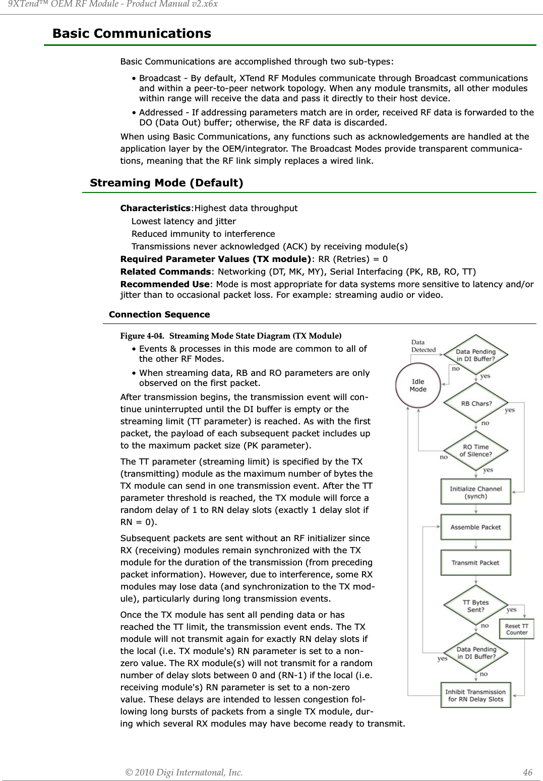
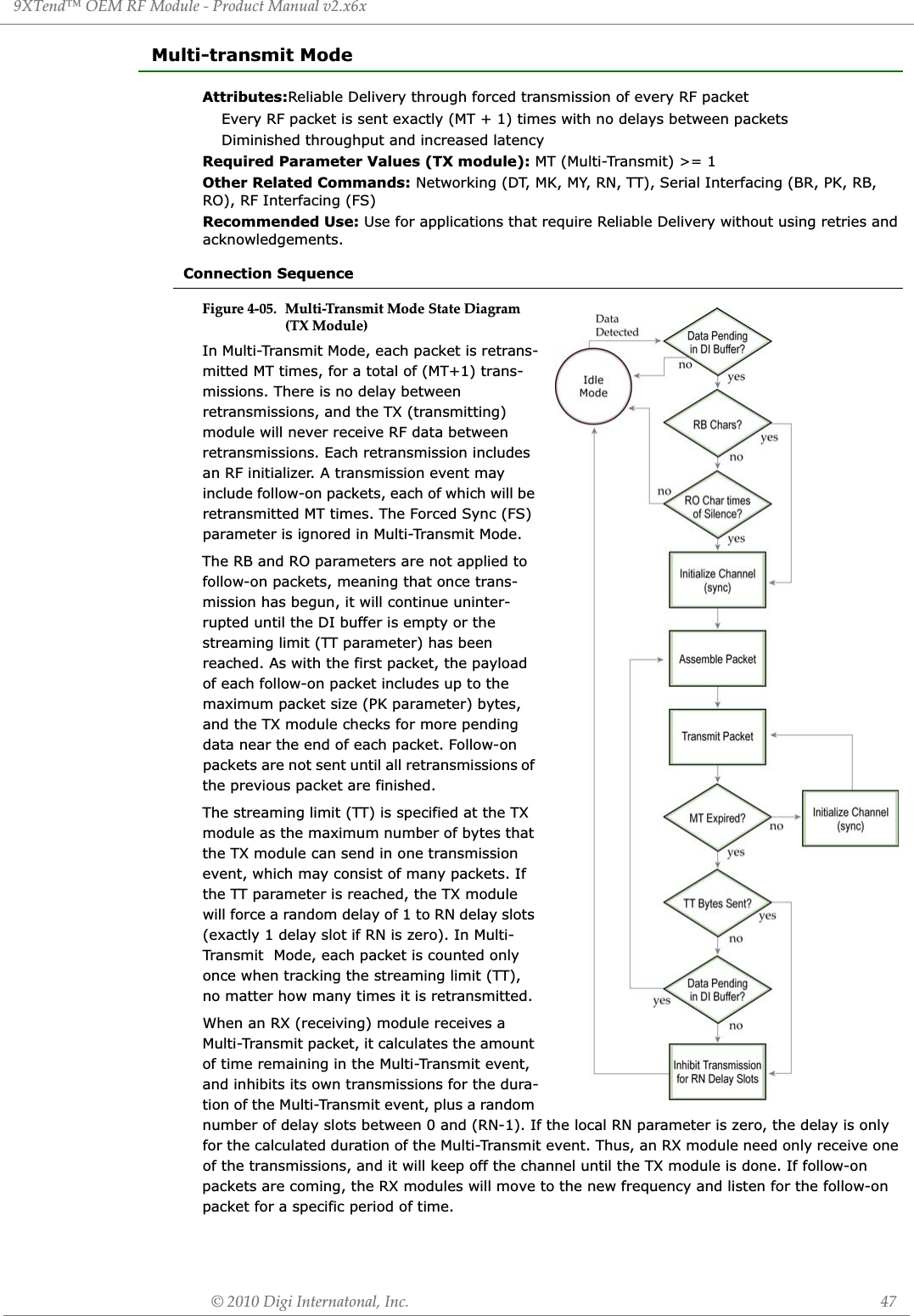
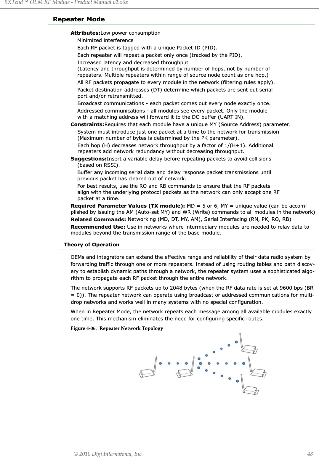
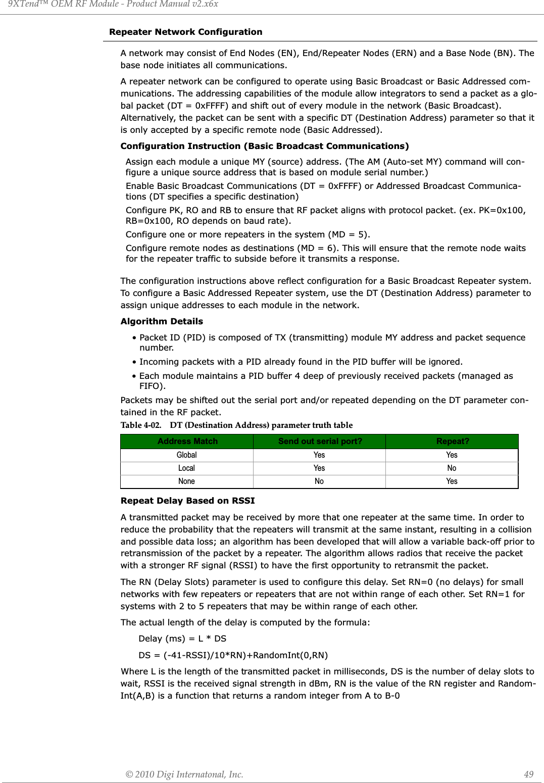
![9XTend™ OEM RF Module - Product Manual v2.x6x© 2010 Digi Internatonal, Inc. 50Response Packet DelayAs a packet propagates through the repeater network, if any node receives the data and generates a quick response, the response needs to be delayed so as not to collide with subsequent retrans-missions of the original packet. To reduce collisions, both repeater and end node radios in a repeater network will delay transmission of data shifted in the serial port to allow any repeaters within range to complete their retransmissions. The time for this delay is computed by the formula: Maximum Delay (ms) = L * DS DS = ((-41-(-100))/10)*RN)+RN+1Where L is the length of the transmitted packet in milliseconds, DS is the number of delay slots to wait, RSSI is the received signal strength in dBm, and RN is the value of the RN register. Use Case - Broadcast Repeater Network Consider modules R1 through R10 each communicating to a PLC using the ModBus protocol and spaced evenly in a line. All ten modules are configured as 'destinations & repeaters' within the scope of Basic Broadcast Communications (MD=5, AM, DT=0xFFFF, PK=0x100, RO=0x03, RB=0x100, RN=1). The Base Host (BH) shifts payload that is destined for R10 to R1. R1 initializes RF communication and transmits payload to nodes R2 through R5 which are all within range of R1. The modules R2 through R5 receive the RF packet and retransmit the packet simultaneously. They also send the data out the serial ports, to the PLCs. Bandwidth ConsiderationsUsing broadcast repeaters in a network reduces the overall network data throughput as each repeater must buffer an entire packet before retransmitting it. For example: if the destination is within range of the transmitter and the packet is 32-bytes long, the transmission will take 12ms on an XTend module operating at 115,200 baud. If the same packet must propagate through two repeaters, it will take 12ms to arrive at the first repeater, 12ms to get to the second and a final 12ms to reach the destination for a total of 36ms. Taking into account UART transfer times (~1ms/byte at 9600 baud), a server to send a 32-byte query and receive a 32-byte response is about 200ms, allowing for 5 polls per second. With the two repeaters in the path, the same query/response sequence would take about 500ms for 2 polls per second.Generally, network throughput will decrease by a factor of 1/(R+1), with R representing the num-ber of repeaters between the source and destination.Table 4-03. Commands used to conęgure repeater functionsATCommandBinaryCommandAT CommandName Range # Bytes ReturnedFactoryDefaultAM 0x3A (58d) Auto-set MY - - -DT 0x00 (0d) Destination Address 0 - 0xFFFF 2 0MD 0x3C (60d) RF Mode 0 - 6 1 0MY 0x2A (42d) Source Address 0 - 0xFFFF 2 0xFFFFRN 0x19 (25d) Delay Slots 0 - 0xFF [slots] 1 0WR 0x08 (8d) Write - - -](https://usermanual.wiki/MaxStream/9XTEND.User-Manual/User-Guide-1251932-Page-50.png)
![9XTend™ OEM RF Module - Product Manual v2.x6x© 2010 Digi Internatonal, Inc. 51Polling Mode (Basic)NOTE: Polling Mode (Basic) and Polling Mode (Acknowledged) [p53] operate in the same way. The only difference between the two modes is in their means of achieving reliable delivery of data. In Polling Mode (Basic), reliable delivery is achieved using multiple transmissions.Attributes:Utilizes high percentage of available network bandwidthEliminates collisionsWorks with reliable delivery (RR or MT parameters)Supports binary data transfersBase module requests packets from remote module by polling a sequential range of addressesBase module is configured to specify the range of addresses being polledUses inter-character delay to create RF packet lengths aligned with protocol packet lengths up to 2048 bytes long.Required Parameter Values (Base): MD (RF Mode) = 3, PB (Polling Begin Address), PE (Polling End Address)Required Parameter Value (Remote): MD (RF Mode) = 4Related Commands: Networking (MT, PD, DT, MY, AM)Constraints: The minimum time interval between polling cycles is configurable. However, if the remote modules cannot all be processed within that time interval, the polling cycle is ineffective (i.e. it will impose no additional delay). In order to ensure a pause between polling cycles, PD must be set to a value which is large enough to accommodate the pause.Recommended Use: Use for point-to-multipoint applications that require Reliable Delivery of data. Use this mode when it is critical that a base module be able to discern data coming from multiple modules.Theory of OperationA ‘Polling Base’ module will cycle through a sequential range of addresses. The ‘Polling Base’ will poll each ‘Polling Remote’ module, wait for a response, then poll the next remote address in the sequence. Each ‘Polling Remote’ will respond by sending the data from its DI (Data In) buffer fol-lowing the RB (Packetization Threshold) & RO (Packetization Timeout) parameters. When there is no eligible data to send, the ‘Polling Remote’ will not respond. The ‘Polling Base’ will poll the next address in the polling sequence after a short delay.Polling Base Configuration:Polling Remote Configuration:Set the MD (RF Mode) parameter (MD = 3).Set MY (Source Address) parameter (MY = 0).Set the sequential range of Polling Addresses using the PB (Polling Begin Address) and PE (Polling End Address) parameters. (Optional) Enable Basic Reliable Delivery (MT >= 0). Note: Acknowledged Reliable Delivery is also supported. Refer to the ‘Polling Mode - Acknowledged’ section for more information. (Optional) Use the PD (Minimum Polling Delay) command to configure a delay between polls to slow down system (if needed).(Optional) Enable API Mode to address remotes within polling range on a packet-by-packet basis.Set the MD (RF Mode) parameter (MD = 4).Configure sequential source addresses for all remote modules using the MY (Source Address) command. Set the DT (Destination Address) parameter to point to ‘Polling Base’ (DT = 0x0000).(Optional) Enable Basic Reliable Delivery (MT >= 0). Note: Acknowledged Reliable Delivery is also supported. Refer to the ‘Polling Mode - Acknowledged’ section for more information.](https://usermanual.wiki/MaxStream/9XTEND.User-Manual/User-Guide-1251932-Page-51.png)
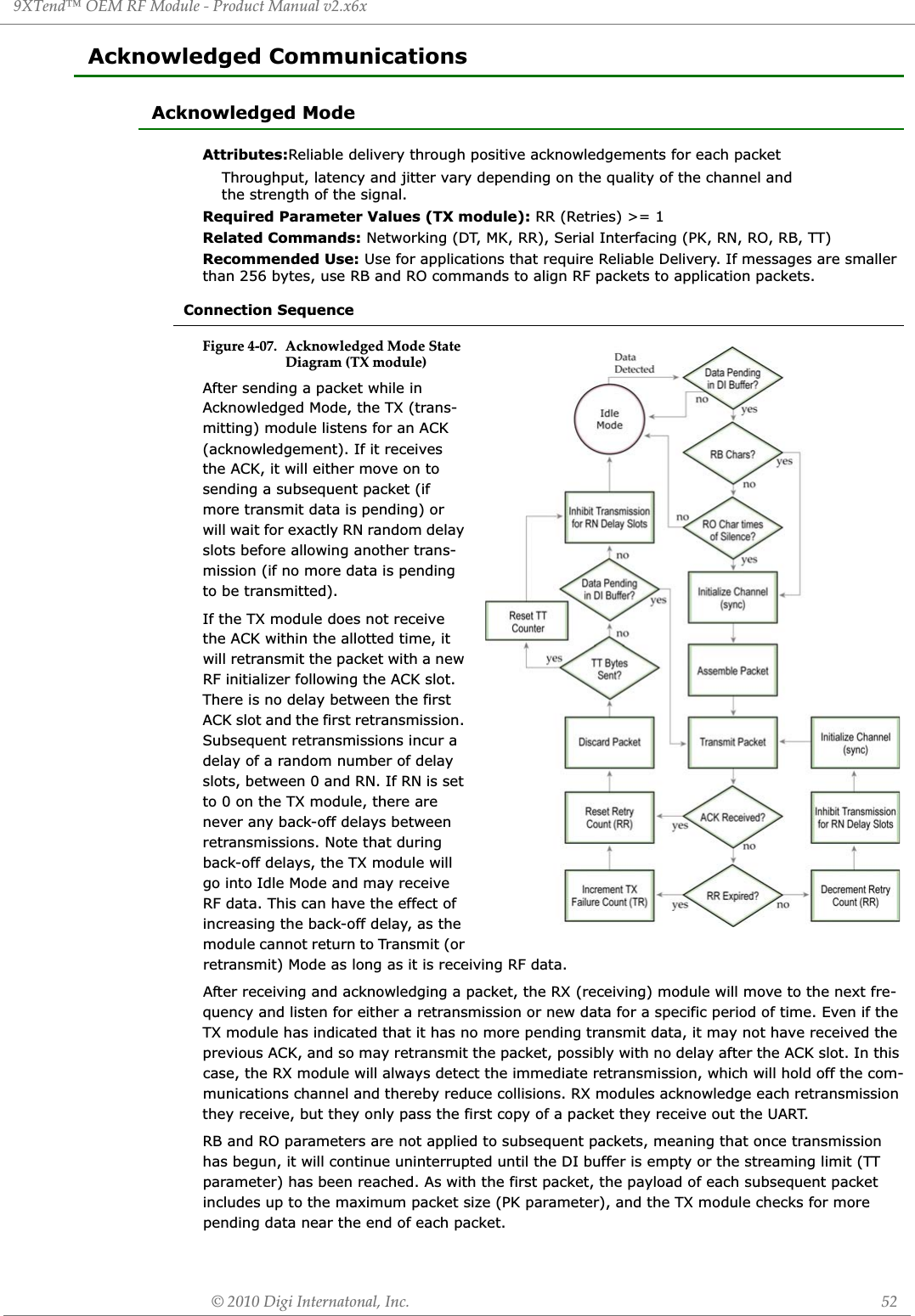

![9XTend™ OEM RF Module - Product Manual v2.x6x© 2010 Digi Internatonal, Inc. 54Polling Mode (Acknowledged)NOTE: Polling Mode (Acknowledged) and Polling Mode (Basic) [p50] operate in the same way. The difference between the two modes is in their means of achieving reliable delivery of data. In Poll-ing Mode (Acknowledged), reliable delivery is achieved using retries and acknowledgements.Attributes:Utilizes high percentage of available network bandwidthEliminates collisionsWorks with reliable delivery (RR or MT parameters)Supports binary data transfersBase module requests packets from remote module by polling a sequential range of addressesBase module is configured to specify the range of addresses being polledUses inter-character delay to create RF packet lengths aligned with protocol packet lengths up to 2048 bytes long.Required Parameter Values (Base): MD (RF Mode) = 3, PB (Polling Begin Address), PE (Polling End Address)Required Parameter Values (Remote): MD (RF Mode) = 4Related Commands: Networking (RR, PD, DT, MY, AM)Constraints: The minimum time interval between polling cycles is configurable. However, if the remote modules cannot all be processed within that time interval, the polling cycle is ineffective (i.e. it will impose no additional delay). In order to ensure a pause between polling cycles, PD must be set to a value which is large enough to accommodate the pause.Recommended Use: Use for point-to-multipoint applications that require Reliable Delivery of data. Use this mode when it is critical that a base module be able to discern data coming from multiple modules.Theory of OperationA ‘Polling Base’ module will cycle through a sequential range of addresses. The ‘Polling Base’ will poll each ‘Polling Remote’ module, wait for a response, then poll the next remote address in the sequence. Each ‘Polling Remote’ will respond by sending the data from its DI (Data In) buffer fol-lowing the RB (Packetization Threshold) & RO (Packetization Timeout) parameters. When there is no eligible data to send, the ‘Polling Remote’ will not respond. The ‘Polling Base’ will poll the next address in the polling sequence after a short delay.Polling Base Configuration:Polling Remote Configuration:Set the MD (RF Mode) parameter (MD = 3).Set MY (Source Address) parameter (MY = 0).Set the sequential range of Polling Addresses using the PB (Polling Begin Address) and PE (Polling End Address) parameters. (Optional) Enable Acknowledged Reliable Delivery (RR >= 0). Note: Basic Reliable Delivery is also supported. Refer to the ‘Polling Mode - Basic section for more information. (Optional) Use the PD (Minimum Polling Delay) command to configure a delay between polls to slow down system (if needed).(Optional) Enable API Mode to address remotes within polling range on a packet-by-packet basis.Set the MD (RF Mode) parameter (MD = 4).Configure sequential source addresses for all remote modules using the MY (Source Address) command. Set the DT (Destination Address) parameter to point to ‘Polling Base’ (DT = 0x0000).(Optional) Enable Acknowledged Reliable Delivery (RR >= 0). Note: Basic Reliable Delivery is also supported. Refer to the ‘Polling Mode - Basic section for more information.](https://usermanual.wiki/MaxStream/9XTEND.User-Manual/User-Guide-1251932-Page-54.png)
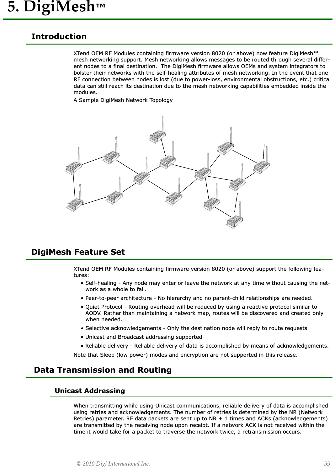
![9XTend™ OEM RF Module - Product Manual v2.x6x© 2010 Digi Internatonal, Inc. 58Table 5-03. )DiagnosticsDL Destination Address Low. Set/Read the destination address (low 32 bits) of a module. 0 - 0xFFFFFFFF Networking 4v8020: 0x00000000v8021: 0x0000FFFF (broadcast)HPHopping Channel. Set/Read the channel hopping sequence. Nodes must have the same hopping sequence to communicate.0 - 9 Networking 1 0IDNetwork Address. Set/Read the user network address. Nodes must have the same network address to communicate.0x10 - 0x7FFF Networking 2 0x3332NHNetwork Hops. Set/Read the maximum number of hops expected in a network route. This value doesn't limit the number of hops allowed, but it is used to calculate timeouts waiting for network acknowledgements.0 – 0xFF[Max number of hops] Networking 2 7NNNetwork Delay Slots. Set/Read the maximum random number of network delay slots before re-broadcasting a network packet. One network delay slot is approximately 168ms.0 – 0x10 Networking 2 3NQNetwork Route Requests. Set/Read the maximum number of route discovery retries allowed to find a path to the destination node. If NQ = 0, a route request will only be sent once.0 – 0x0A Networking 2 3NRNetwork Retries. Set/Read the maximum number of network packet delivery attempts. If NR > 0, packets sent will request a network ACK and can be resent up to NR+1 times if no ACKs are received.0 – 0xFF Networking 2 1SH Source Address High. Set/Read the source address (high 32 bits) of a module.0x0013A200[read-only] Networking 2 0x0013A200SL Source Address Low. Set/Read the source address (low 32 bits) of a module.0 - 0xFFFFFFFF[read-only] Networking 2 variesAT Command AT Command NameParame-ter RangeCommand Category# Bytes ReturnedFactory DefaultATGuard Time After. Set/Read required DI pin silent time after the Command Sequence Characters of the Command Mode Sequence. The DI silent time is used to prevent inadvertent entrance into Command Mode.0 – 0xFFFF[x 100 msec]Command Mode Options 20x0A(1 decimal second)BTGuard Time Before. Set/Read required DI pin silent time before the Command Sequence Characters of the Command Mode Sequence. The DI silent time is used to prevent inadvertent entrance into Command Mode.0 - 0xFFFF [x 100 msec]Command Mode Options 2 0x0A (10d)CCCommand Sequence Character. Set/Read the ASCII character used between guard times of the AT Command Mode Sequence (BT + CC + AT)0x20 - 0x7F Command Mode Options 10x2B [ASCII "+"]CNExit Command Mode. Explicitly exit the module from AT Command Mode. (The same action occurs automatically when CT expires.)-- Command Mode Options -- --](https://usermanual.wiki/MaxStream/9XTEND.User-Manual/User-Guide-1251932-Page-58.png)
![9XTend™ OEM RF Module - Product Manual v2.x6x© 2010 Digi Internatonal, Inc. 59Table 5-04. DiagnosticsCTCommand Mode Timeout. Set/Read the amount of inactive time that elapses before the module automatically exits from AT Command Mode.2 - 0xFFFF [x 100 ms]Command Mode Options 2 0xC8 (200d)E0 Echo Off. Turn off character echo in AT Command Mode. By default, echo is off. -- Command Mode Options -- --E1 Echo On. Turn on character echo in AT Command Mode. Each input character is echoed back to out to the host. -- Command Mode Options -- --AT Command AT Command Name Parameter Range Command Category# Bytes ReturnedFactory Default--4scitsongaiDAFFB5x0 ot ACC2x0egatloV draoBV%CFCommand Format. Set/Read the format of data entered and displayed for commands. Use decimal format unless Hex is forced or preferred.0 – 20 = Decimal with units 1 - Hexadecimal without units. All input and output is in hexadecimal format. 2 - Decimal without units.Diagnostics 1 1DBReceived Signal Strength. Read the receive signal strength (in decibels relative to milliWatts) of the last received packet.0x6E - 0x28 [read-only]Sample Output: -88 dBm (when ATCF = 0)58 (when ATCF = 1)-88 (when ATCF = 2)Diagnostics 2 --ER Receive Error Count. Set/Read the number of receive-errors. 0 - 0xFFFF Diagnostics 2 0GD Receive Good Count. Set/Read the count of good received RF packets. 0 - 0xFFFF Diagnostics 2 0HV Hardware Version Read and display the version of the hardware 0 – 0Xffff Diagnostics 2 --RC Ambient Power - Single Channel. Examine & report the power level on a given channel.0 - 0x31 [dBm, read-only]Sample output: -78 dBm [when CF = 0] 4e [when CF = 1] -78 [when CF = 2]Diagnostics 1 --RM Ambient Power - All Channels. Examine and report power levels on all channels. No parameter - 0x7D0 Diagnostics 2 --RPRSSI PWM Timer. Enable PWM ("Pulse Width Modulation") output on the Config/RSSI pin (pin 11 of the OEM RF Module)0 - 0xFF [x 100 msec] Diagnostics 1 0x20 (32d)TP Board Temperature. Read the current temperature of the board. 0 - 0x7F [read-only] Diagnostics 1 --TR Delivery Failure Count. Report the number of retransmit failures. 0 - 0xFFFF [read-only] Diagnostics 2 0VLFirmware Version – verbose. Read detailed version information including application build date and time.Returns string Diagnostics -- --](https://usermanual.wiki/MaxStream/9XTEND.User-Manual/User-Guide-1251932-Page-59.png)
![9XTend™ OEM RF Module - Product Manual v2.x6x© 2010 Digi Internatonal, Inc. 60VR Firmware Version. Read the 4-digit version number. 0 - 0xFFFF [read-only] Diagnostics 2 --WAActive Warning Numbers. Report the warning numbers of all active warnings - one warning number per line.Returns string Diagnostics -- --WN Warning Data. Report data for all active and sticky warnings Returns string Diagnostics -- --WSSticky Warning Numbers. Report warning numbers of all warnings active since the last use of the WS or WN commandReturns string Diagnostics -- --](https://usermanual.wiki/MaxStream/9XTEND.User-Manual/User-Guide-1251932-Page-60.png)
![9XTend™ OEM RF Module - Product Manual v2.x6x© 2010 Digi Internatonal, Inc. 61Table 5-05. Serial InterfacingAT Command AT Command Name Parameter RangeCom-mand Category# Bytes ReturnedFactory DefaultAP API Enable. Set/Read the API mode of the radio.0 – 20 = API Disabled1 = API-enabled2 = API-enabled (w/escaped control characters)Serial Interfacing 10BDInterface Data Rate. Set/Read the serial interface data rate (baud rate) used between the RF module and host.0 - 8 (standard rates)0 = 1200 bps1 = 24002 = 48003 = 96004 = 192005 = 384006 = 576007 = 1152008 = 2304000x39 - 0x1C9C38 (non-standard rates)Serial Interfacing 43(9600 baud)CD GPO2 Configuration. Select/Read the behavior of the GPO2 line (pin 3).0 – 40 = RX LED (when data is received whether or not the address is valid.)1 = Assert RX LED2 = De-assert RX LED3 = (reserved)4 = RX LED (valid address only)Serial Interfacing 12CS GPO1 Configuration. Select/Read the behavior of the GP01 pin (pin 9)0 – 40 = RS-232 CTS flow control1 = RS-485 TX enable low2 = CTS always High3 = RS-485 TX enable high4 = CTS always LowSerial Interfacing 10FL Software Flow Control. Enable/Disable software flow control (XON/XOFF).0 – 10 = Disabled1 = EnabledSerial Interfacing 10FTFlow Control Threshold. Set/Read the flow control threshold. When FT bytes have accumulated in the DI buffer (UART Receive), CTS is de-asserted or the XOFF software flow control character is transmitted.0x10 – 0x17E[Bytes]Serial Interfacing 20x16D (365 decimal)NB Parity. Select/Read parity settings.0 – 40 = No parity1 = 8-bit even2 = 8-bit odd3 = Forced high4 = Forced lowSerial Interfacing 10RBPacketization Threshold. Set/Read the character threshold value. RF transmission begins after receiving RB bytes, or after receiving at least 1 byte and detecting RO character times of silence on the UART.0 – 0xD3[Bytes]Serial Interfacing 20xC8 (200 decimal)](https://usermanual.wiki/MaxStream/9XTEND.User-Manual/User-Guide-1251932-Page-61.png)
![9XTend™ OEM RF Module - Product Manual v2.x6x© 2010 Digi Internatonal, Inc. 62API OperationAPI operation requires that communication with the module be done through a structured inter-face (data is communicated in frames in a defined order). The API specifies how commands, com-mand responses and module status messages are sent and received from the module using a UART data Frame.API Frame SpecificationsTwo API modes are supported and both can be enabled using the AP (API Enable) command. Use the following AP parameter values to configure the module to operate in a particular mode:"AP = 0 (default): Transparent Operation (UART Serial line replacement)API modes are disabled. AP = 1: API Operation AP = 2: API Operation (with escaped characters)Any data received prior to the start delimiter is silently discarded. If the frame is not received cor-rectly or if the checksum fails, the data is silently discarded. API Operation (AP parameter = 1)When this API mode is enabled (AP = 1), the UART data frame structure is defined as follows:Figure 5-01. UART Data Frame StructureROPacketization Timeout. Set/Read the number of character times with no UART data before a packet is created for RF output (assuming UART data was received prior to the idle time). If RO = 0, it is ignored and no data will be transmitted until RB characters are in the DO buffer.0 - 0xFFFF [x UART character time]Serial Interfacing 23RT GPI1 Configuration. Set/Read the behavior of the GPI1 pin (pin 10).0 – 20 = No RTS flow control 2 = RTS flow controlSerial Interfacing 10SB Stop Bits. Set/Read the number of stop bits in the data packet.0 – 10 = 1 stop bit 1 = 2 stop bitsSerial Interfacing 10](https://usermanual.wiki/MaxStream/9XTEND.User-Manual/User-Guide-1251932-Page-62.png)
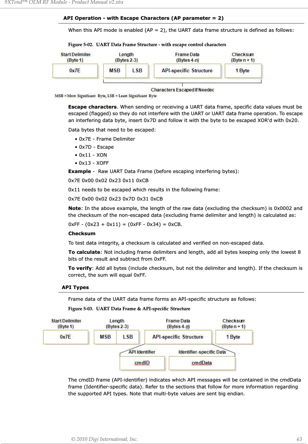
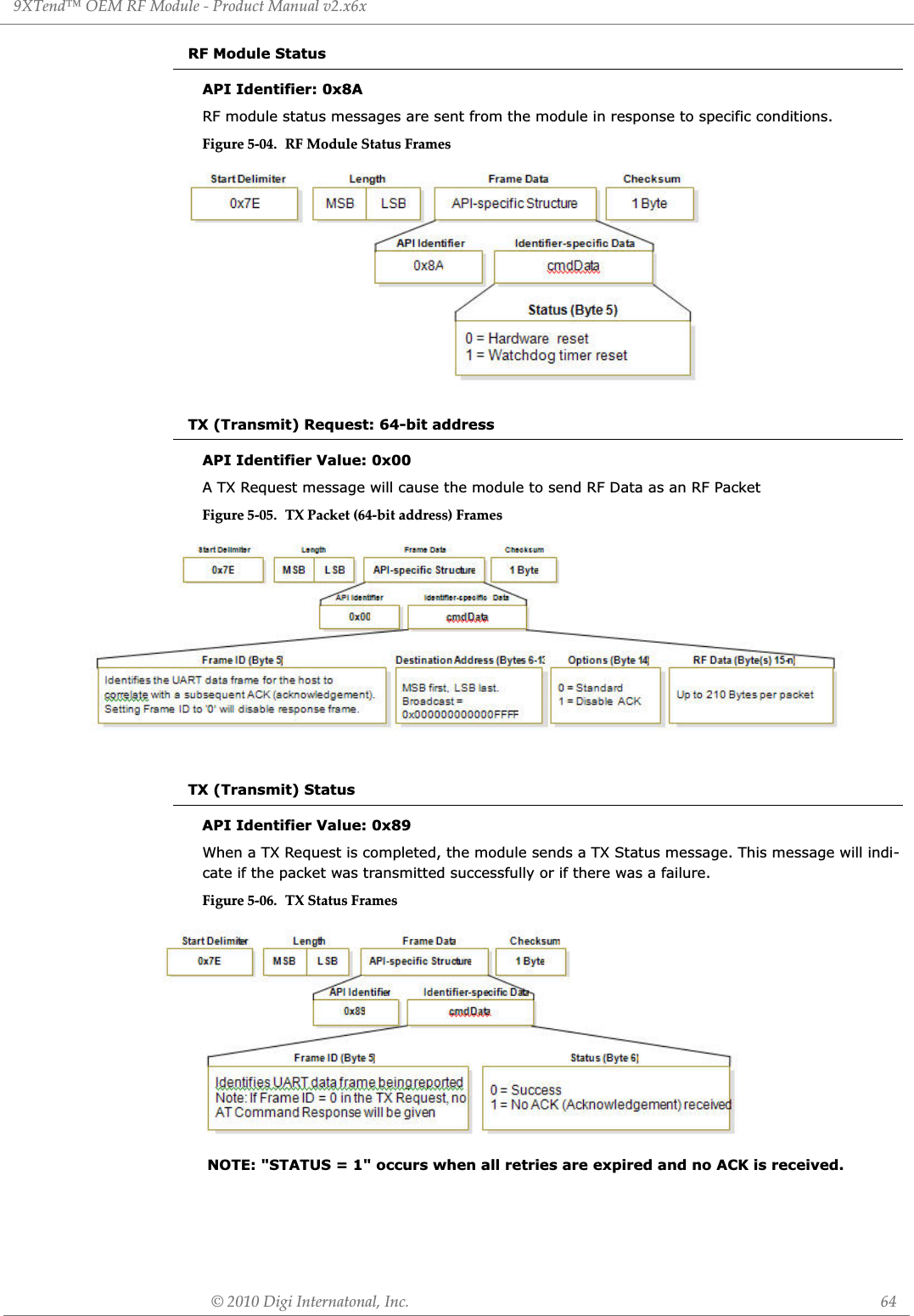
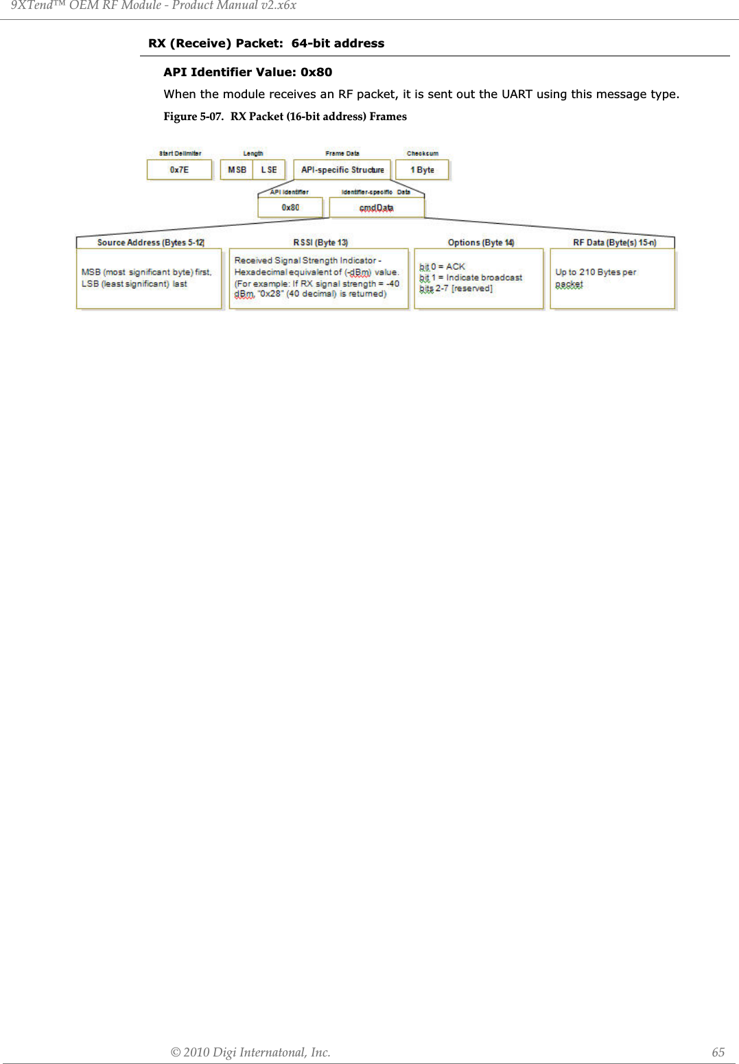
![© 2010 MaxStream, Inc. 66Appendix A: Agency ęFCC (United States) CertificationThe XTend OEM RF Module complies with Part 15 of the FCC rules and regulations. Compliance with the labeling requirements, FCC notices and antenna usage guidelines is required.In order to operate under Digi’s FCC Certification, OEMs/integrators must comply with the follow-ing regulations:OEM Labeling RequirementsWARNING: The Original Equipment Manufacturer (OEM) must ensure that FCC labeling requirements are met. This includes a clearly visible label on the outside of the final product enclosure that displays the text shown in the figure below.Figure A-01. Required FCC el OEM duct ntining the XTend OEM RF dule FCC NoticesIMPORTANT: The XTend OEM RF Module has been certified by the FCC for use with other prod-ucts without any further certification (as per FCC section 2.1091). Modifications not expressly approved by Digi could void the user's authority to operate the equipment.IMPORTANT: OEMs must test final product to comply with unintentional radiators (FCC section 15.107 & 15.109) before declaring compliance of their final product to Part 15 of the FCC Rules.IMPORTANT: The RF module has been certified for remote and base radio applications. If the module will be used for portable applications, the device must undergo SAR testing.This equipment has been tested and found to comply with the limits for a Class B digital device, pursuant to Part 15 of the FCC Rules. These limits are designed to provide reasonable protection against harmful interference in a residential installation. This equipment generates, uses and can radiate radio frequency energy and, if not installed and used in accordance with the instructions, may cause harmful interference to radio communications. However, there is no guarantee that interference will not occur in a particular installation. If this equipment does cause harmful interference to radio or television reception, which can be determined by turning the equipment off and on, the user is encouraged to try to correct the inter-ference by one or more of the following measures: Re-orient or relocate the receiving antenna, Increase the separation between the equipment and receiver, Connect equipment and receiver to outlets on different circuits, or Consult the dealer or an experienced radio/TV technician for help.1. The OEM/integrator must ensure that the text provided with this device [Figure A-01] is placed on the outside of the final product and within the final product operation manual.2. The XTend OEM RF Module may only be used with antennas that have been tested and approved for use with this module [refer to ‘FCC-approved Antennas’ section].Contains FCC ID: OUR-9XTENDThe enclosed device complies with Part 15 of the FCC Rules. Operation is subject to the following two conditions: (i.) this device may not cause harmful interference and (ii.) this device must accept any inter-ference received, including interference that may cause undesired operation.](https://usermanual.wiki/MaxStream/9XTEND.User-Manual/User-Guide-1251932-Page-66.png)
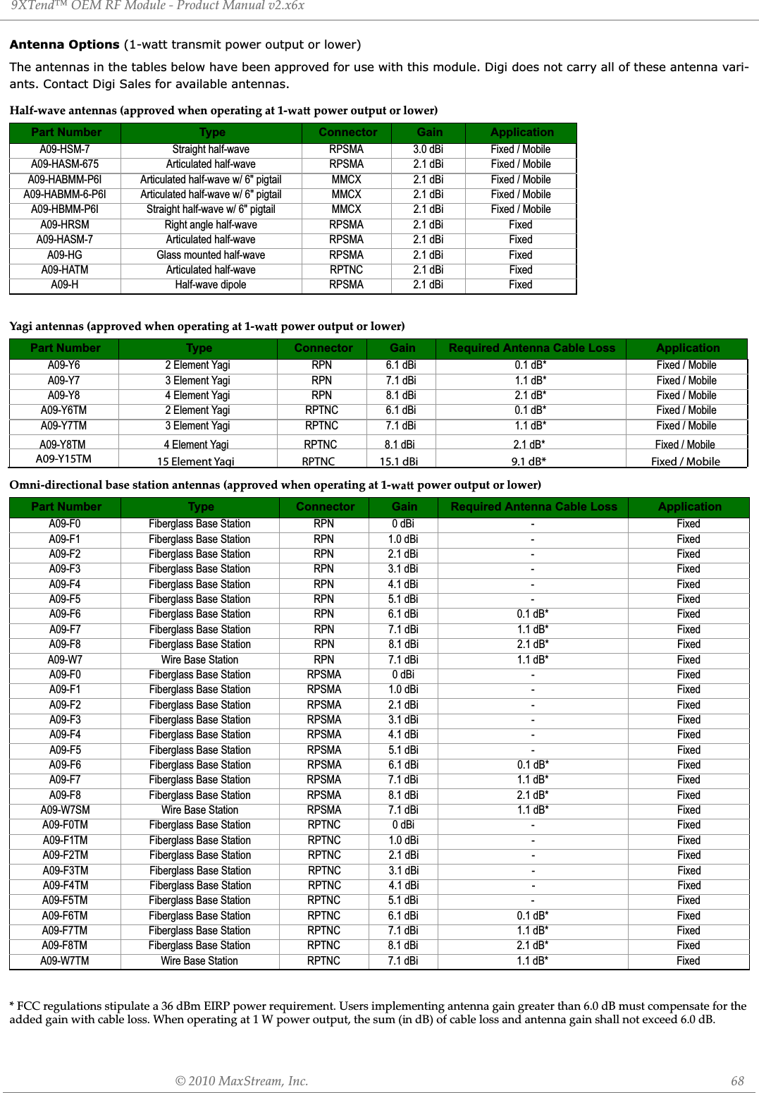
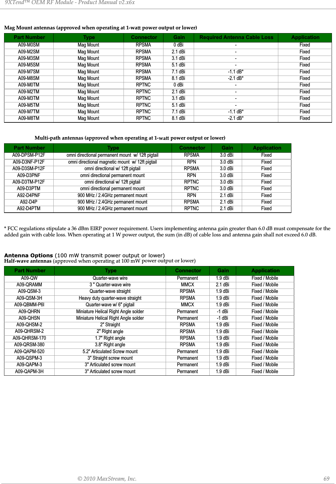

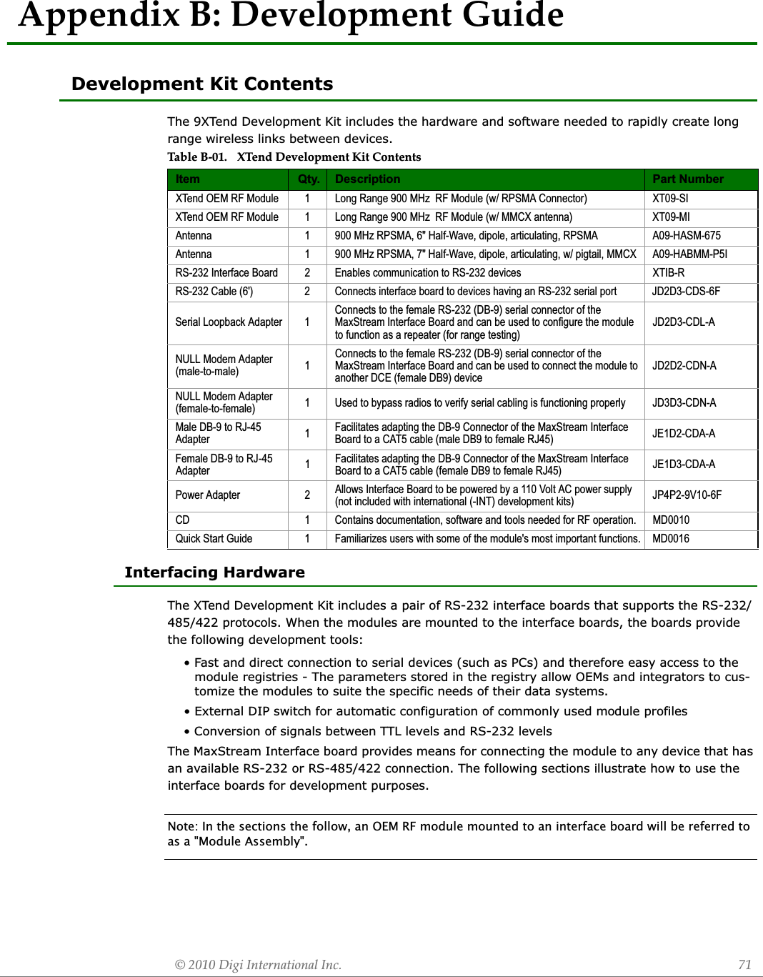
![9XTend™ OEM RF Module - Product Manual v2.x6x© 2010 Digi Internatonal, Inc. 72XTIB-R RS-232/485 Interface BoardFigure B-03. DIP Switch SeĴings of the XTIB-R (RS-232/485) Interface Board B-01a. Config (Configuration) SwitchFigure B-01. Front View The Config Switch provides an alternate method for entering into Command Mode. To enter Command Mode at the module's default RF data rate, hold the Configuration Switch down for two seconds. B-01b. I/O & Power LEDsThe LEDs visualize gigantic status information and indicate module activity as follows:Yellow (top LED) = Serial Data Out (to host)Green (middle) = Serial Data In (from host)Red (bottom) = Power/TX Indicator (Red light is on when powered; it pulses on/off briefly during RF transmission.)) B-01c. DB-9 Serial PortStandard female DB-9 (RS-232) connector. This connector can also be used for RS-485 and RS-422 connections. B-01d. RSSI LEDsRSSI LEDs indicate the amount of fade margin present in an active wireless link. Fade margin is defined as the difference between the incoming signal strength and the module's receiver sensitivity.3 LEDs ON = Very Strong Signal (> 30 dB fade margin)2 LEDs ON = Strong Signal (> 20 dB fade margin)1 LED ON = Moderate Signal (> 10 dB fade margin)0 LED ON = Weak Signal (< 10 dB fade margin) B-01e. Power Connector7-28 VDC power connector (Center positive, 5.5/2.1mm)Note: The XTIB-R interface board can accept voltages as low as 5V. Contact MaxStream Technical Support to enable this option. B-02a. DIP SwitchFigure B-02. Back View DIP Switch automatically configures the module to operate in differ-ent modes during the power-on sequence. Each time the module assembly (interface board + module) is powered-on, intelligence on the board programs the attached module according to the positions of the DIP Switch.Figure B-03 illustrates DIP Switch settings. Table B-02 summarizes the configurations triggered by the positions of the DIP Switch.B-01a.Conęg SwitchB-01b.I/O & Power LEDsB-01c.DB-9 Serial PortB-01dRSSI LEDsB-01e.Power ConnectorB-02a.DIP SwitchRefer to the tables in the ‘Automatic DIP Switch ętions’ section [next page] regarding conęgura-tions triggered by the positions of the DIP Switch (during power-up).](https://usermanual.wiki/MaxStream/9XTEND.User-Manual/User-Guide-1251932-Page-72.png)
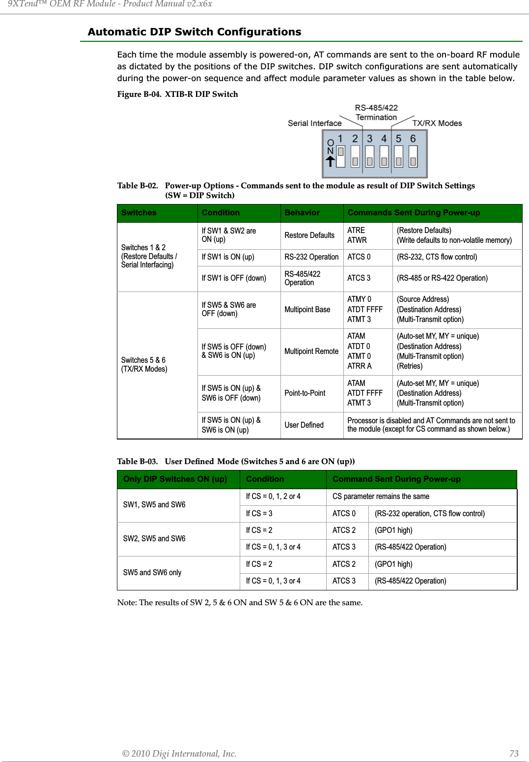
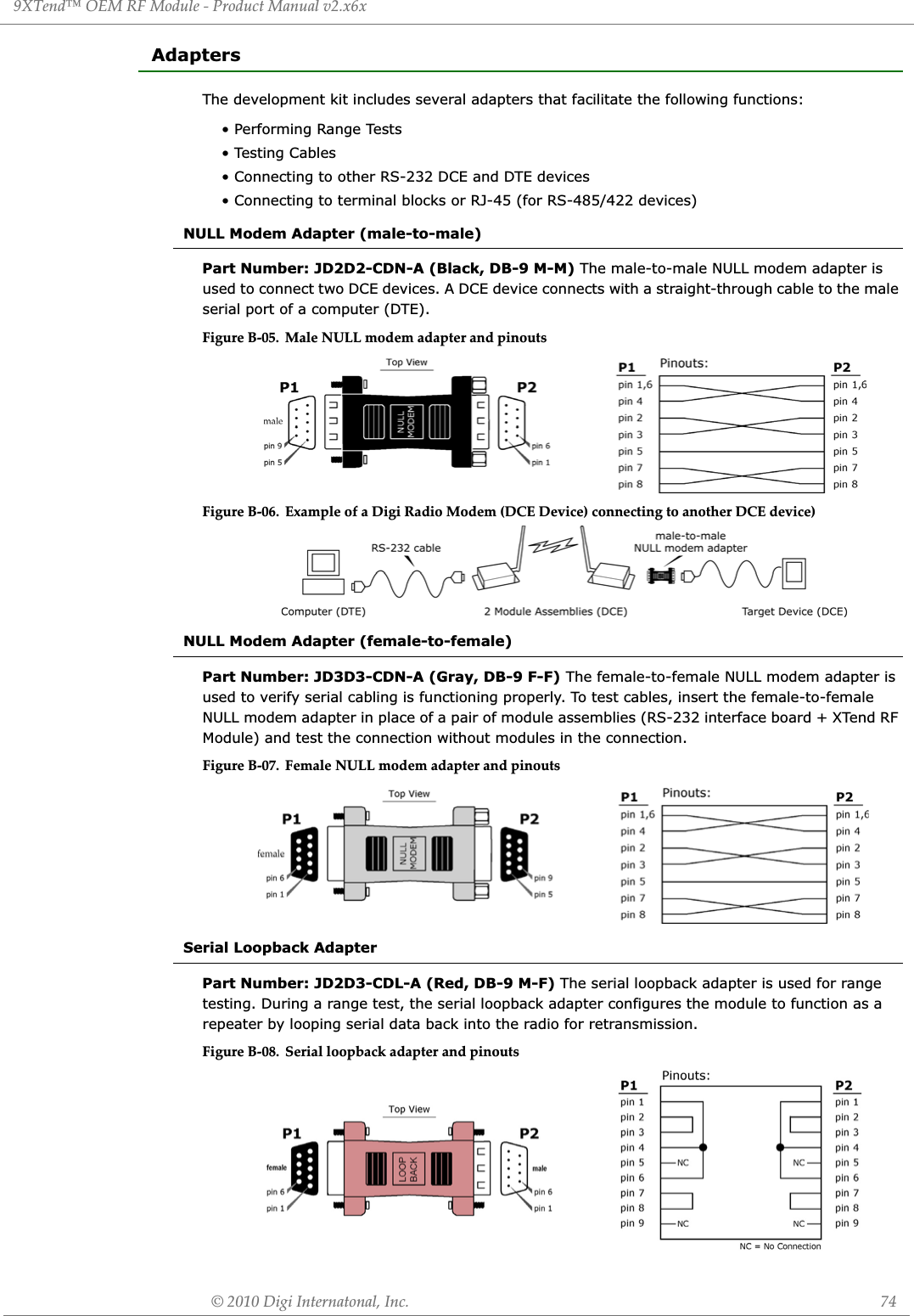
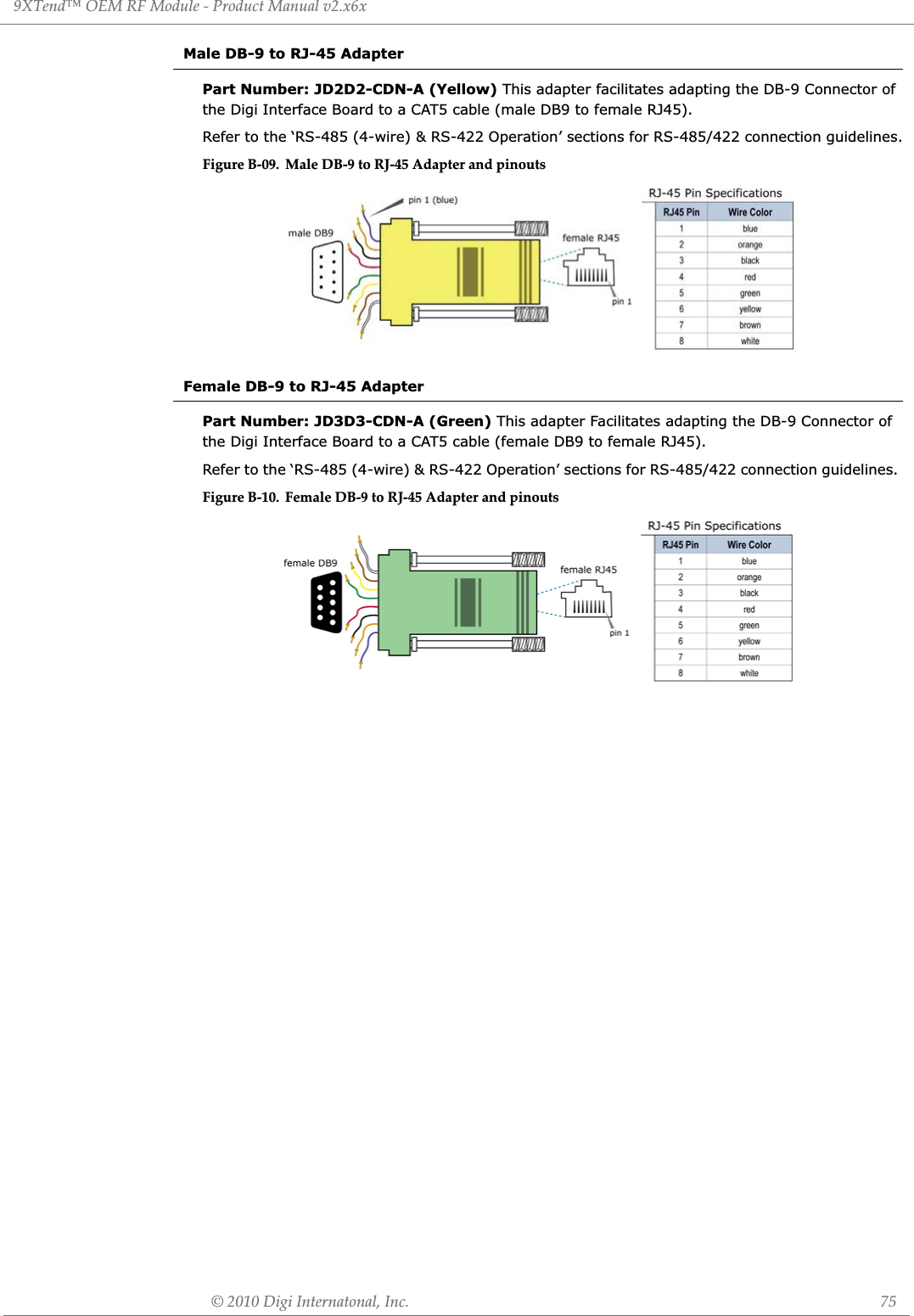
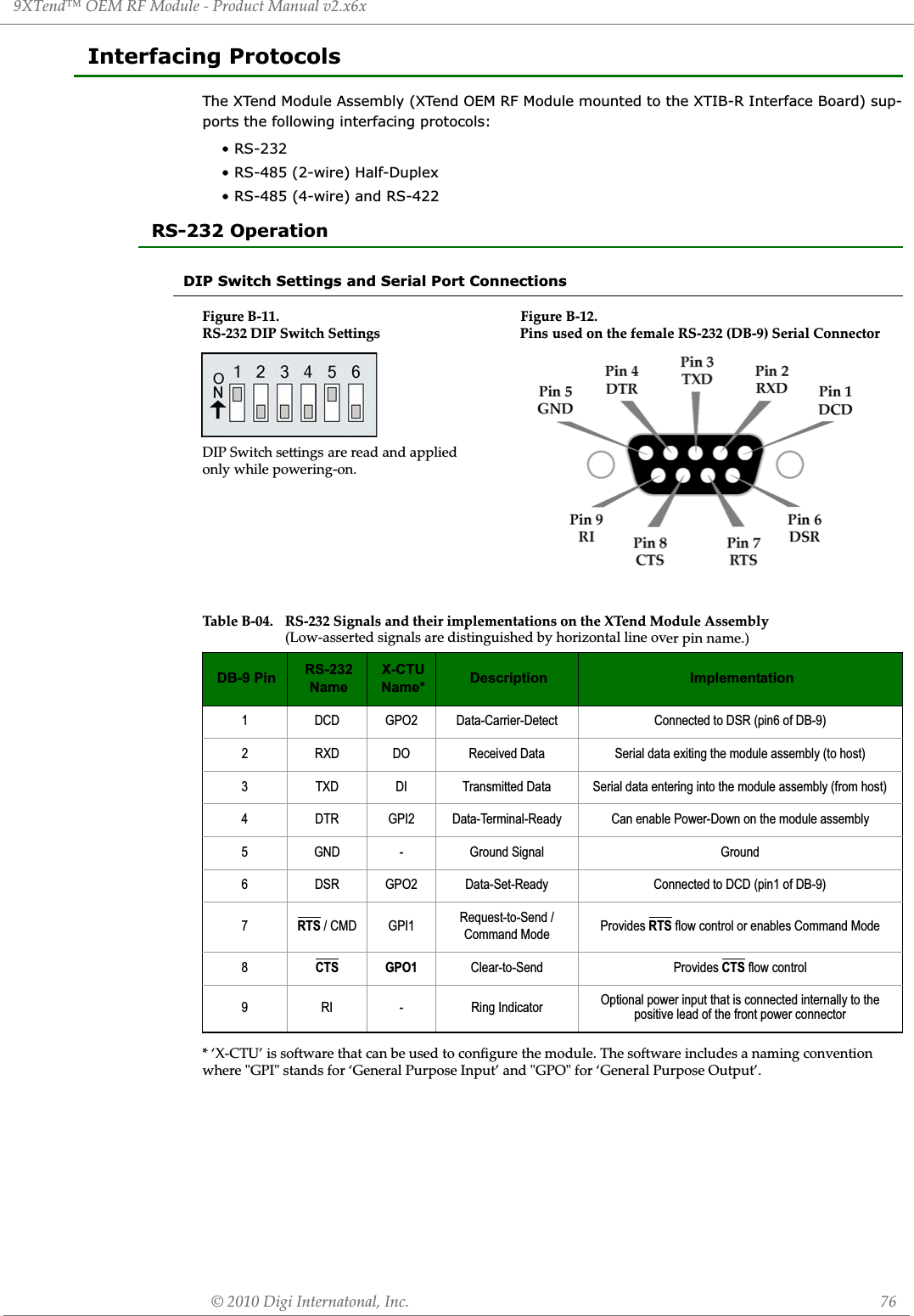
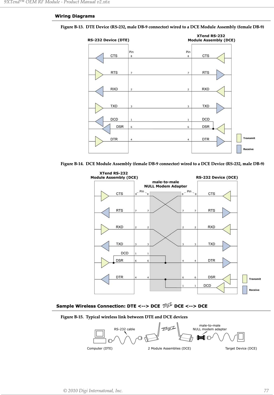
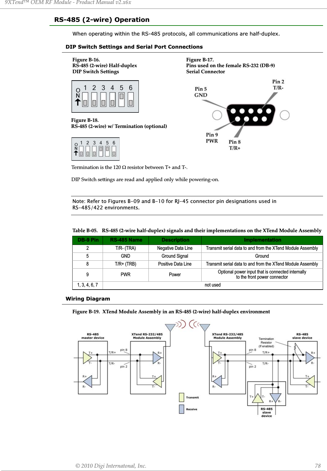
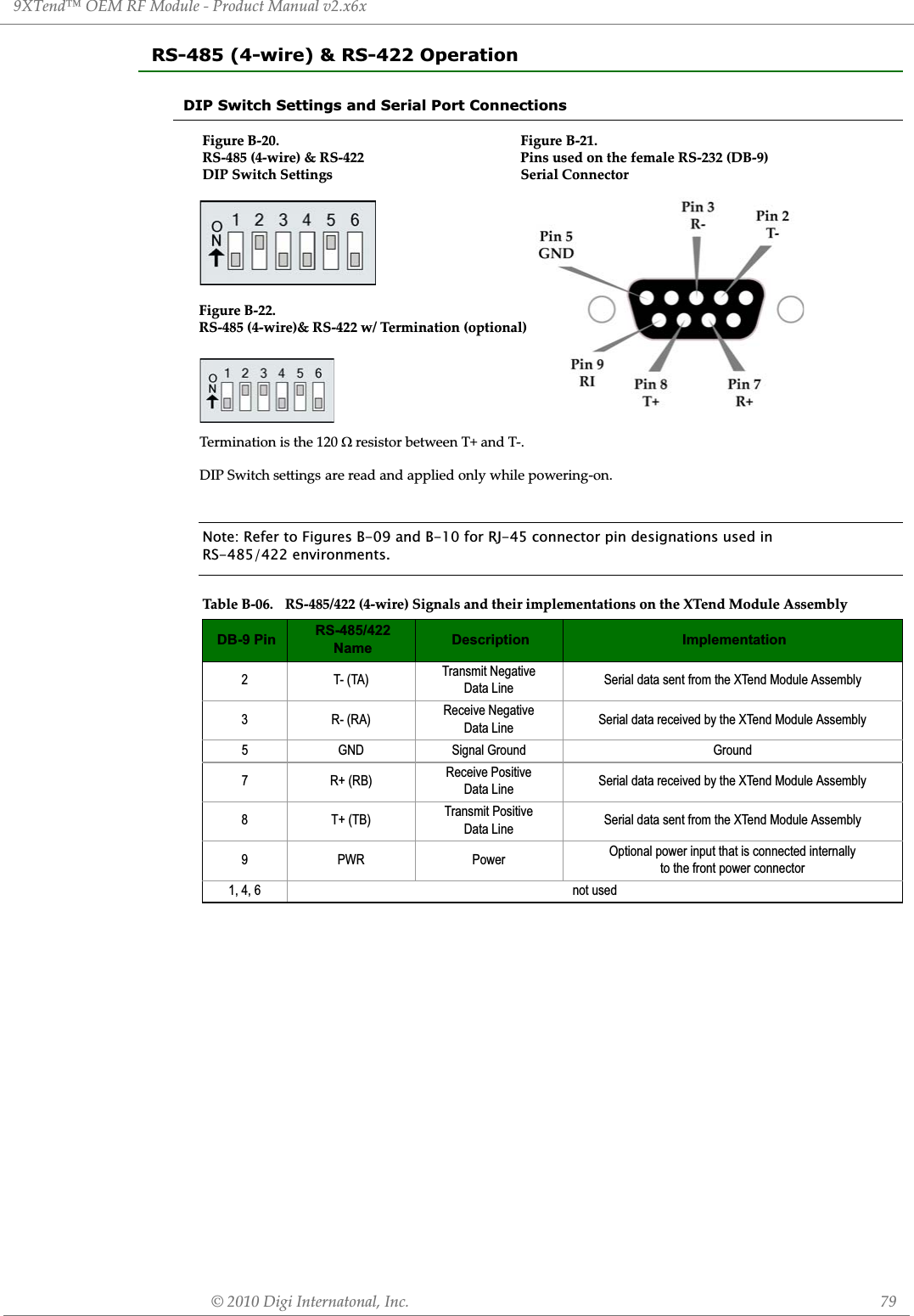
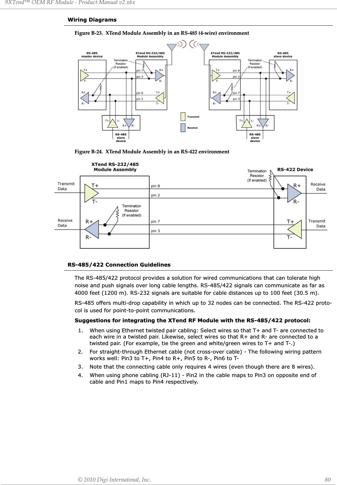
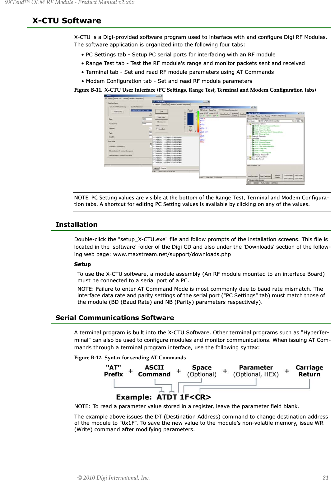
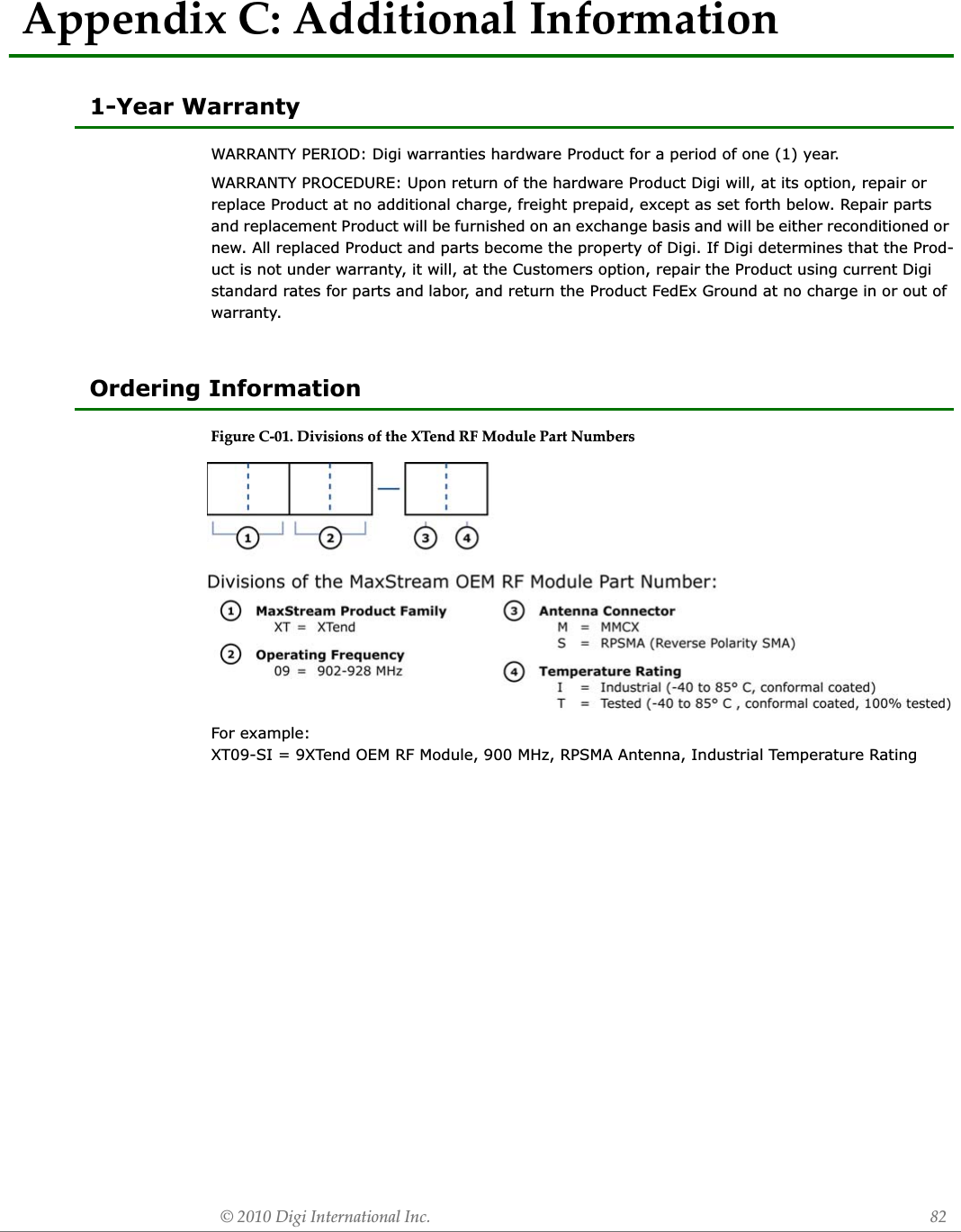
![9XTend™ OEM RF Module - Product Manual v2.x6x© 2010 MaxStream, Inc. 83Contact MaxStreamFor the best in wireless data solutions and support, please use the following resources:Office hours are 8:00 am - 5:00 pm [U.S. Mountain Standard Time]Documentation: www.maxstream.net/support/downloads.phpTechnical Support: Phone. (866) 765-9885 toll-free U.S.A. & Canada(801) 765-9885 WorldwideLive Chat. www.digi.com/moc.igid.www//:ptth:troppus-E support/eservice/eservicelo-gin.jsp](https://usermanual.wiki/MaxStream/9XTEND.User-Manual/User-Guide-1251932-Page-83.png)