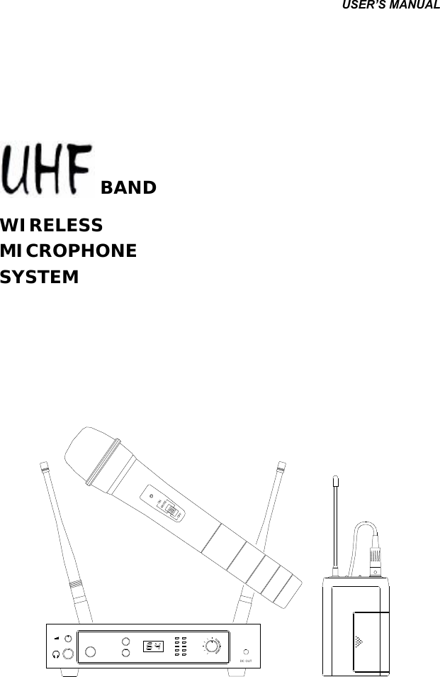
Mascot Electric UF-9R Wireless Handheld Transmitter Microphone User Manual UR UF 9R
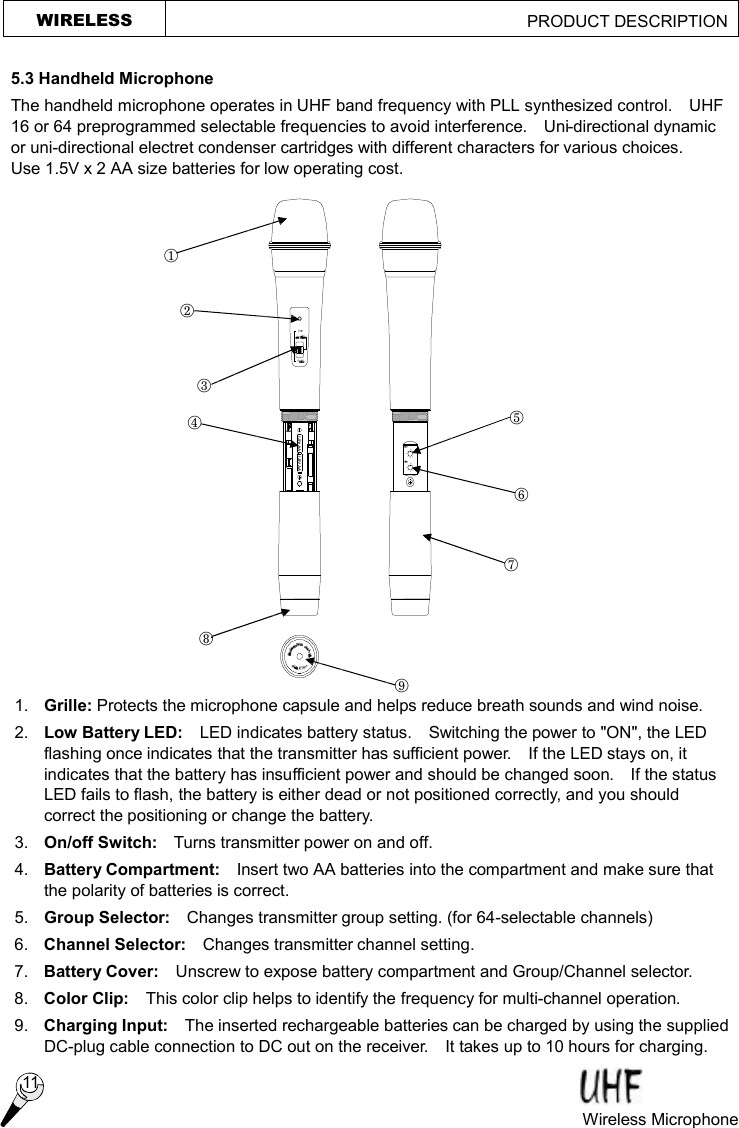
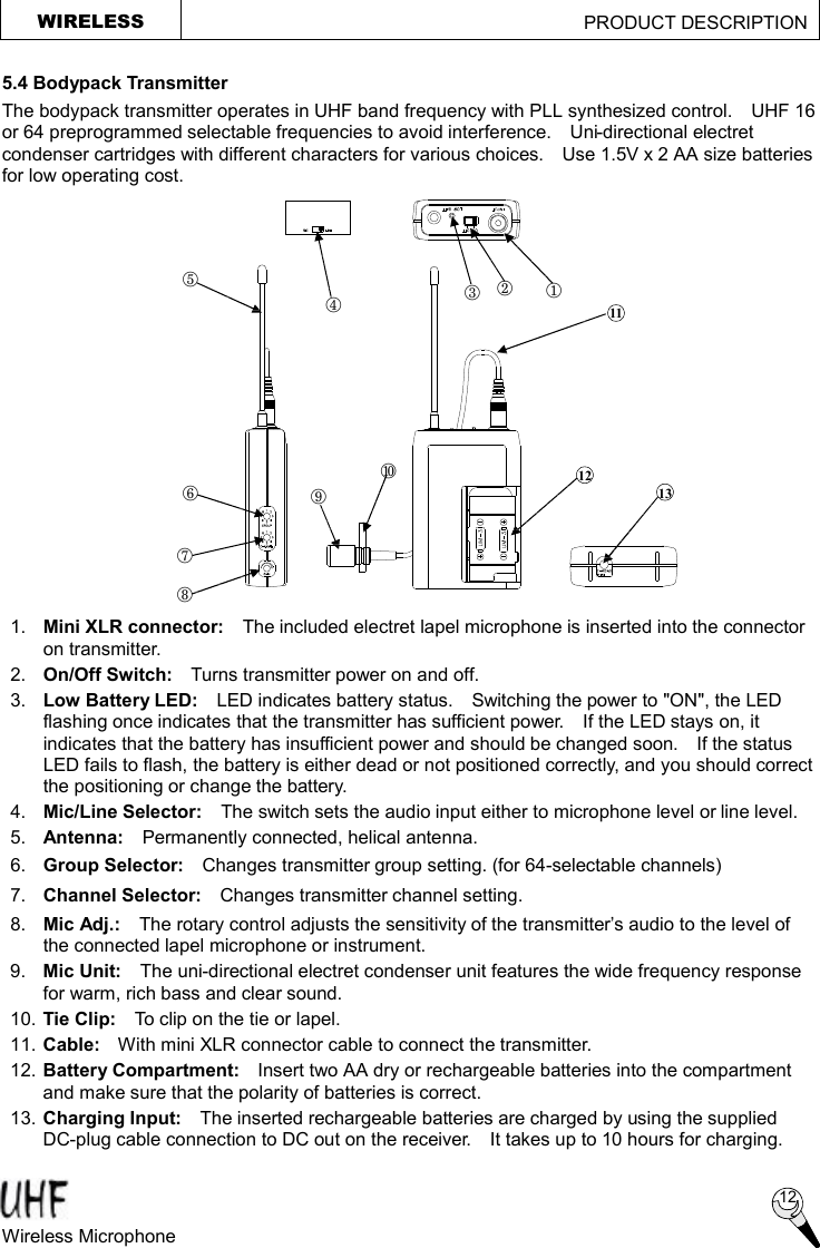
Mascot Electric Co., Ltd. Wireless Handheld Transmitter Microphone UR UF 9R
UserManual.wiki
>
Mascot Electric
>
UF 9R User Manual
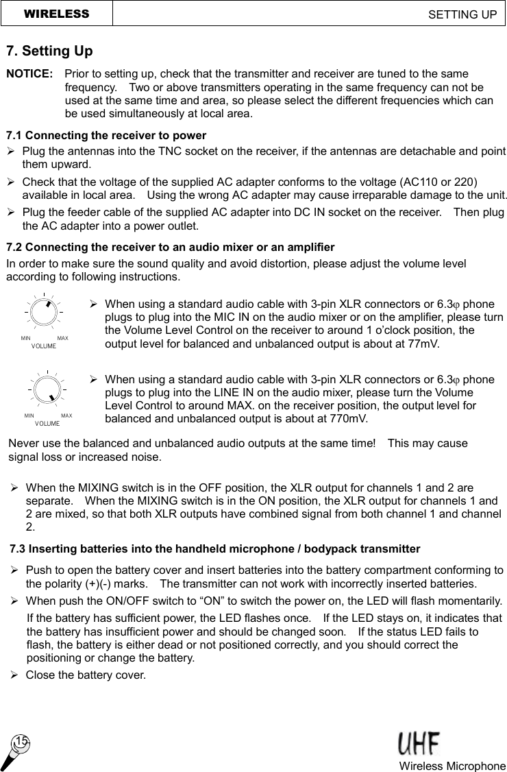
User Manual
Navigation menu
Upload a User Manual
Namespaces
Wiki Guide
HTML
PDF
Info
Views
User Manual
Discussion / Help
Navigation