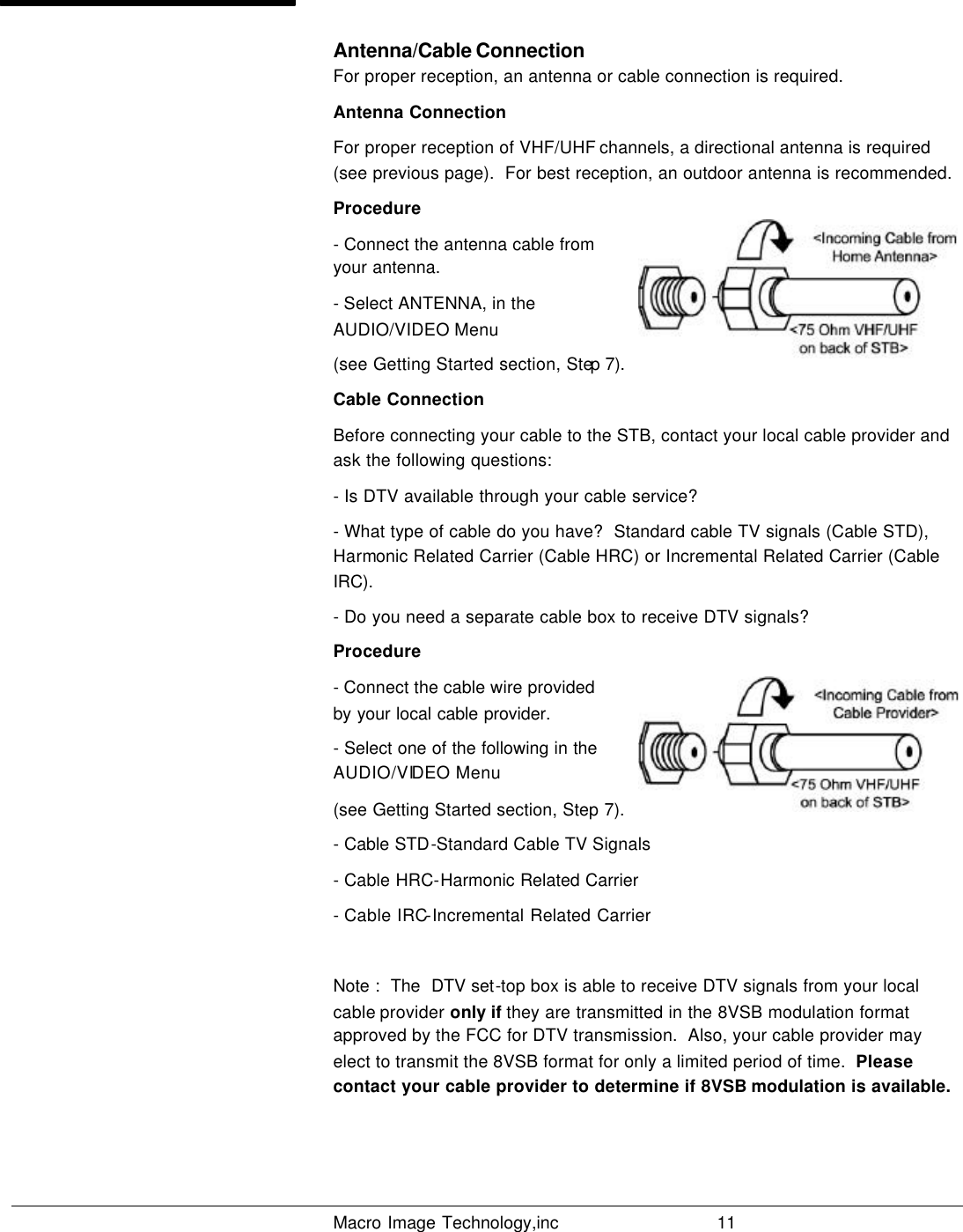
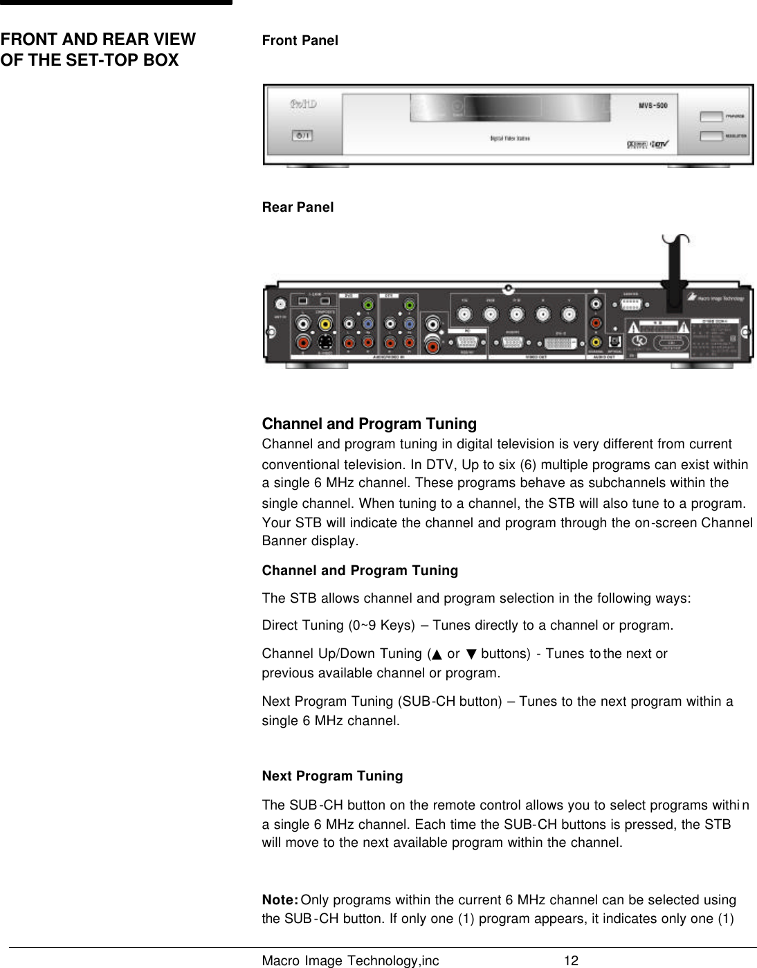
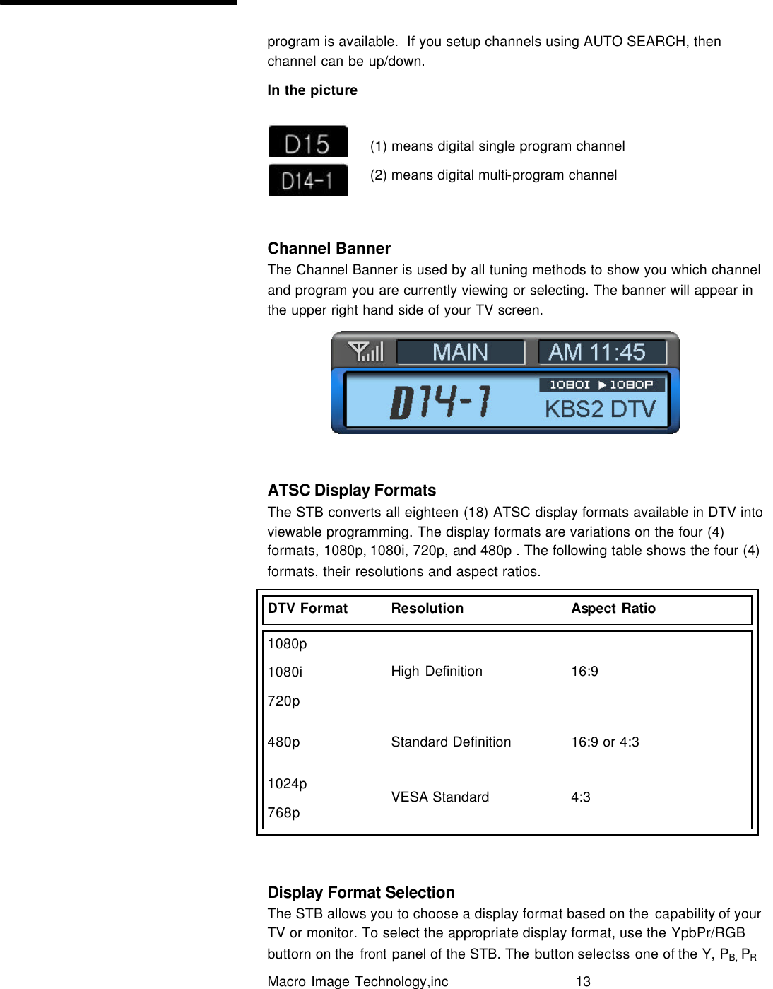
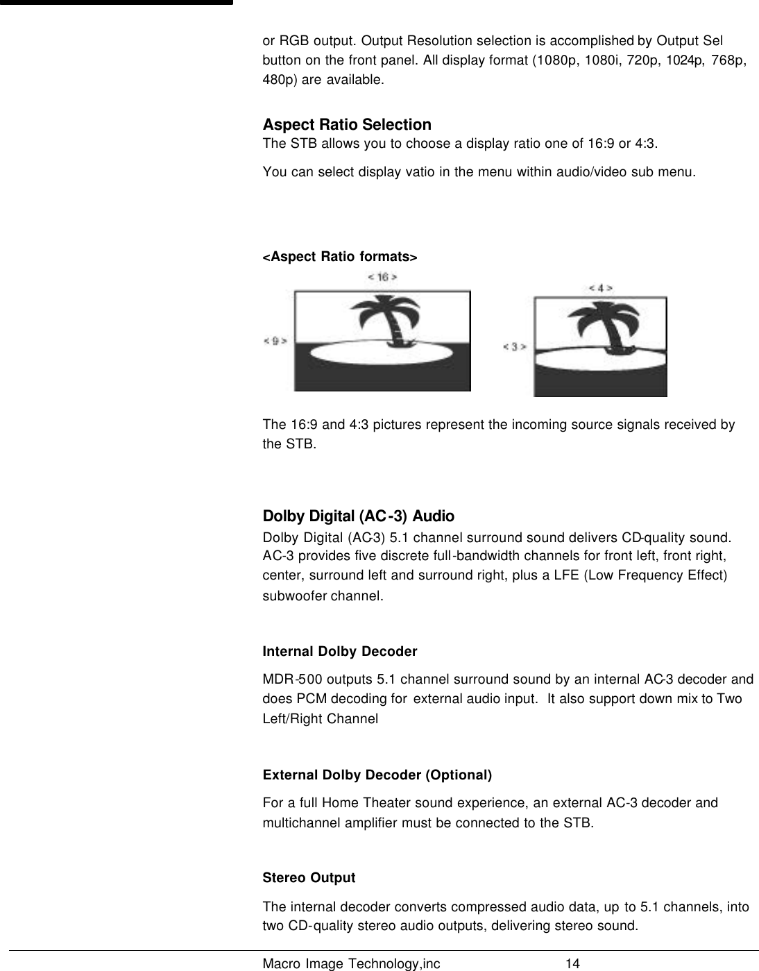
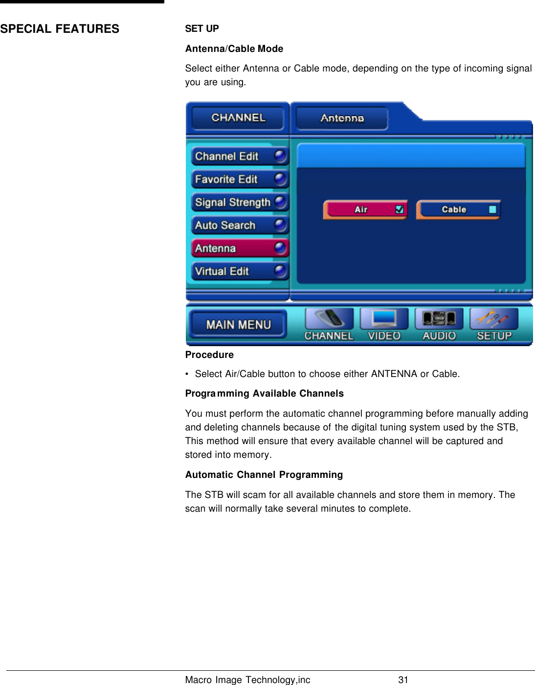
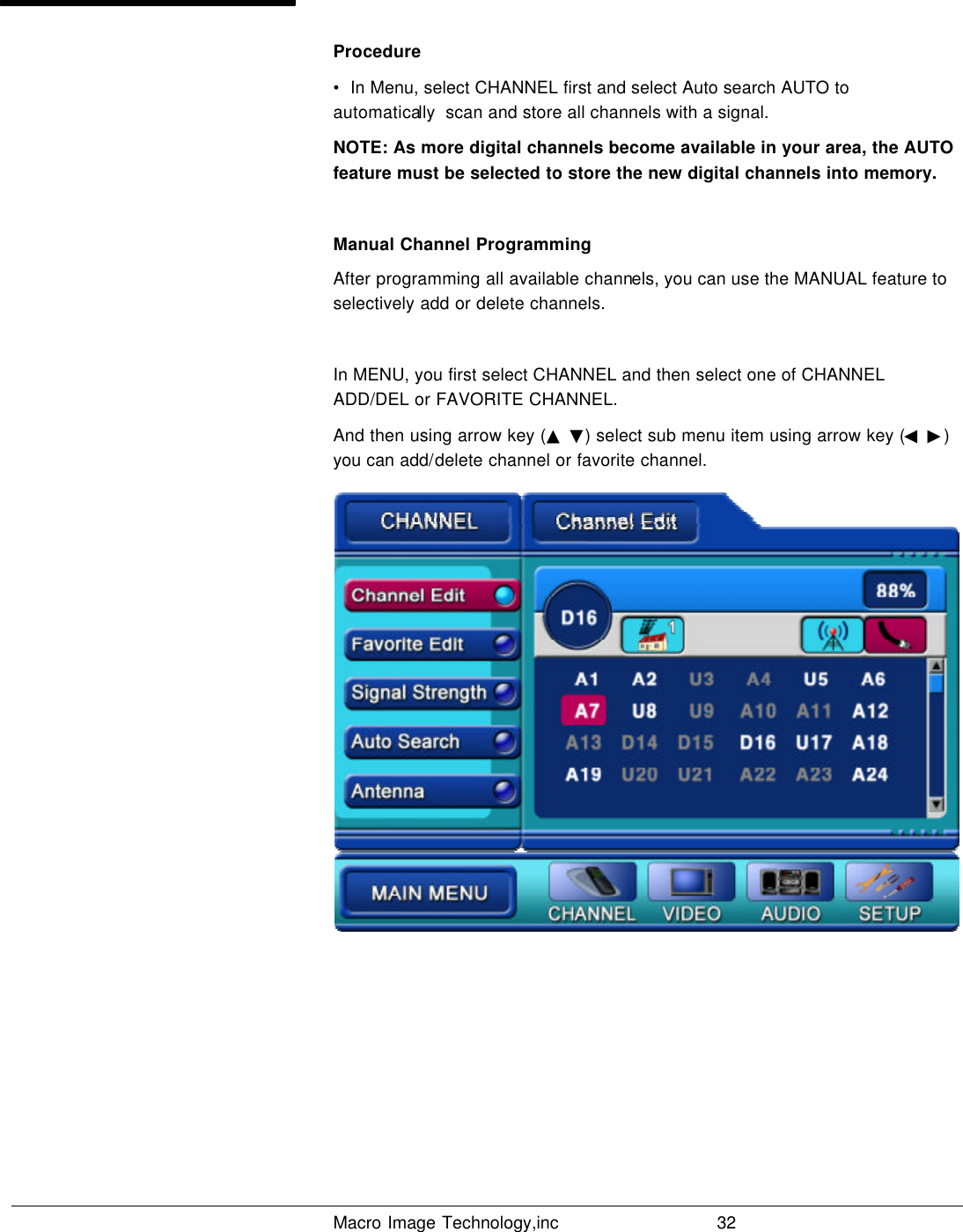
Macro Image Technology MVS-500 Digital Video Station User Manual MDR 500 20021115
Macro Image Technology, Inc Digital Video Station MDR 500 20021115
UserManual.wiki
>
Macro Image Technology
>
MVS-500 User Manual
>
Users Manual
Contents
1.
Users Manual
2.
Users Manual Appendix
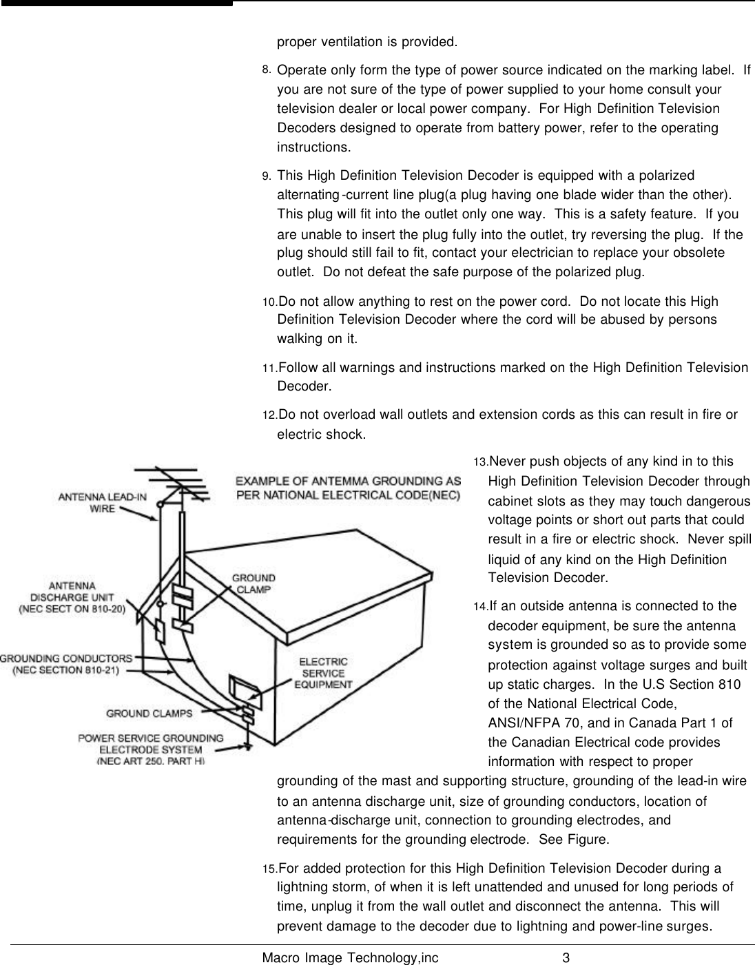
Users Manual
Navigation menu
Upload a User Manual
Namespaces
Wiki Guide
HTML
PDF
Info
Views
User Manual
Discussion / Help
Navigation