MOELCA S R L 1504 AUTOMATIC EXTRACTOR OF EMOCOMPONENTS User Manual Rev 1 05
MOELCA S.R.L. AUTOMATIC EXTRACTOR OF EMOCOMPONENTS Rev 1 05
UserManual.wiki
>
MOELCA S R L
>
1504 User Manual
User Manual
Navigation menu
Upload a User Manual
Namespaces
Wiki Guide
HTML
PDF
Info
Views
User Manual
Discussion / Help
Navigation

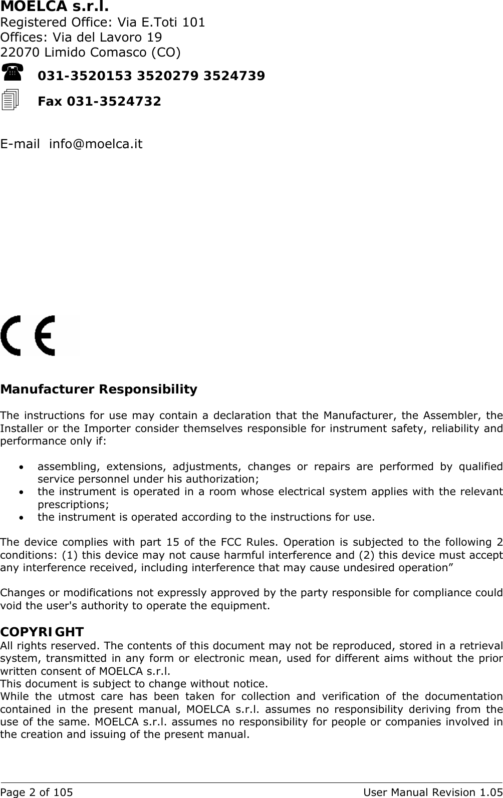
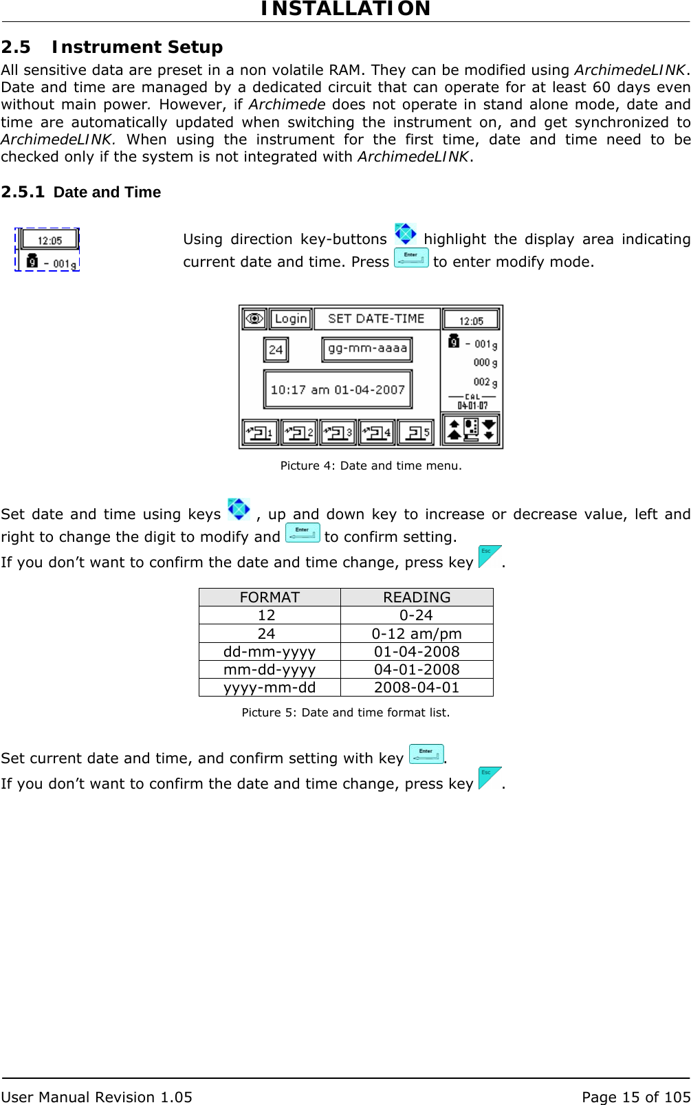
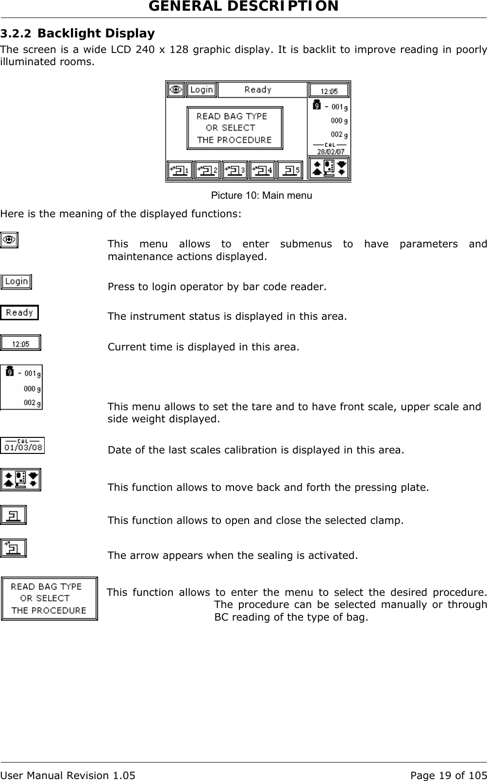
![CONTENTS Page 6 of 105 User Manual Revision 1.05 WARRANTY 3 1 INTRODUCTION 11 1.1 Intended Use.............................................................................. 11 1.2 Key features............................................................................... 11 2 INSTALLATION 13 2.1 Unpacking Archimede .................................................................. 13 2.2 Positioning Archimede.................................................................. 13 2.3 Assembling scale, filter holders and antenna. .................................. 13 2.4 Switching on Archimede ............................................................... 14 2.5 Instrument Setup........................................................................ 15 2.5.1 Date and Time 15 2.5.2 Procedures Setup Check 16 3 GENERAL DESCRIPTION 17 3.1 Upper Panel ............................................................................... 17 3.2 Front Panel ................................................................................ 17 3.2.1 Keyboard 18 3.2.2 Backlight Display 19 3.3 Rear Panel ................................................................................. 20 3.4 Side Panel.................................................................................. 20 3.5 Meaning of Procedure Parameters.................................................. 21 3.6 Procedure Parameters Display....................................................... 24 3.7 Maintenance Display.................................................................... 24 3.8 Date and Time............................................................................ 24 3.9 Scales ....................................................................................... 25 3.10 Manual Control of Plate Forward Moving ......................................... 25 3.11 Clamps Manual Control ................................................................ 26 4 USING ARCHIMEDE 27 4.1 Switching on .............................................................................. 27 4.2 System Self-check....................................................................... 27 4.3 Use as a scale............................................................................. 30 4.4 Use as a sealing unit.................................................................... 30 4.5 Use as manual separator.............................................................. 31 4.6 Separation Procedure .................................................................. 32 4.6.1 Questions 33 4.6.2 PROCEDURE 1 T & T triple PPP or PRP + RCC. 34 4.6.3 PROCEDURE 2 T & T quadruple PPP or PRP BC + RCC. 39 4.6.4 PROCEDURE 3 Top & Bottom triple PPP+BC+RCC. 44 4.6.5 PROCEDURE 4 Top & Bottom quadruple PPP+BC+RCC. 49 4.6.6 PROCEDURE 5 Separation from PRP to PPP+PLT 54 4.6.7 PROCEDURE 7 Single or Pool of Buffy for PLT + residual BC with filter 59 4.6.8 PROCEDURE 8 Separation of Erythrocytes Washing 64 4.6.9 PROCEDURE 10 [a]UMBILICAL CORD 69 4.6.10 PROCEDURE 11 [b] ALIQUOTE SEPARATION 74 4.6.11 PROCEDURE 13 [d] T & T for RCC diluted in Plasma + Predefined HCT. 79 5 SCALE CALIBRATION 85 6 DATA TRANSFER 87 6.1 WLAN ........................................................................................ 87 6.2 Firmware Update and Procedures Protocols ..................................... 87 6.3 Data transmission and reception ................................................... 88 6.3.1 Example of procedure data transmission: 90 6.3.2 List of symbols used in the transmission protocol: 90 7 TROUBLESHOOTING 91](https://usermanual.wiki/MOELCA-S-R-L/1504/User-Guide-1140271-Page-6.png)
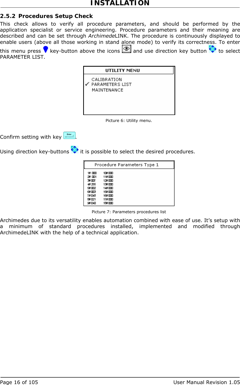
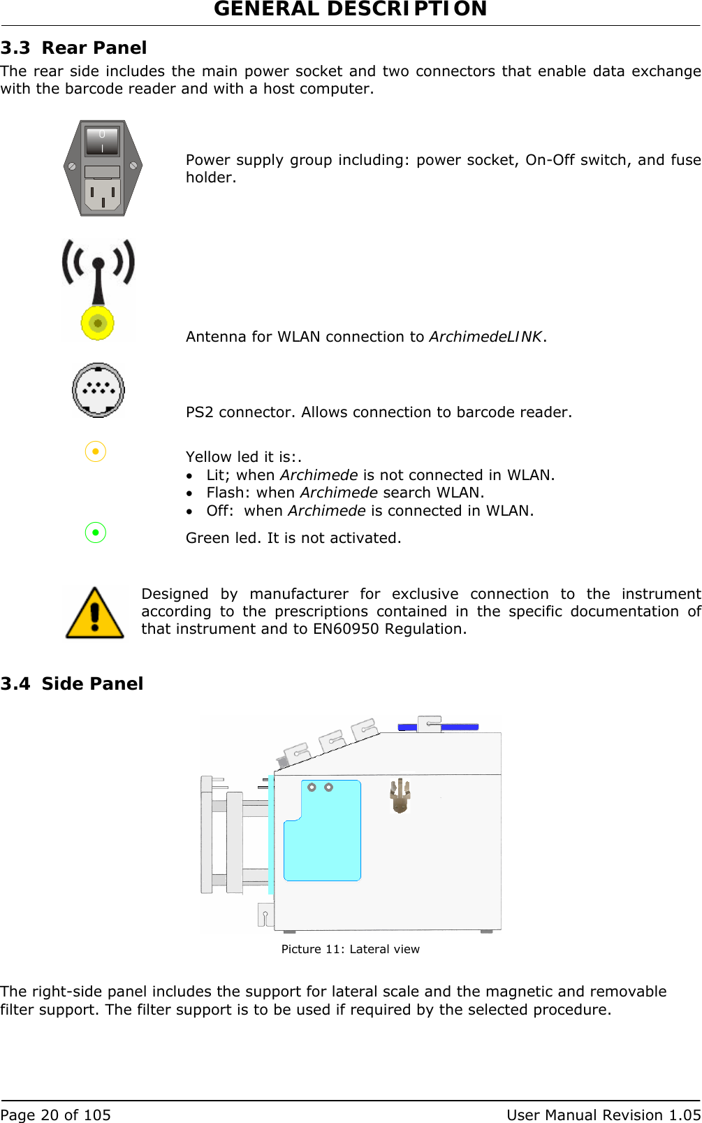
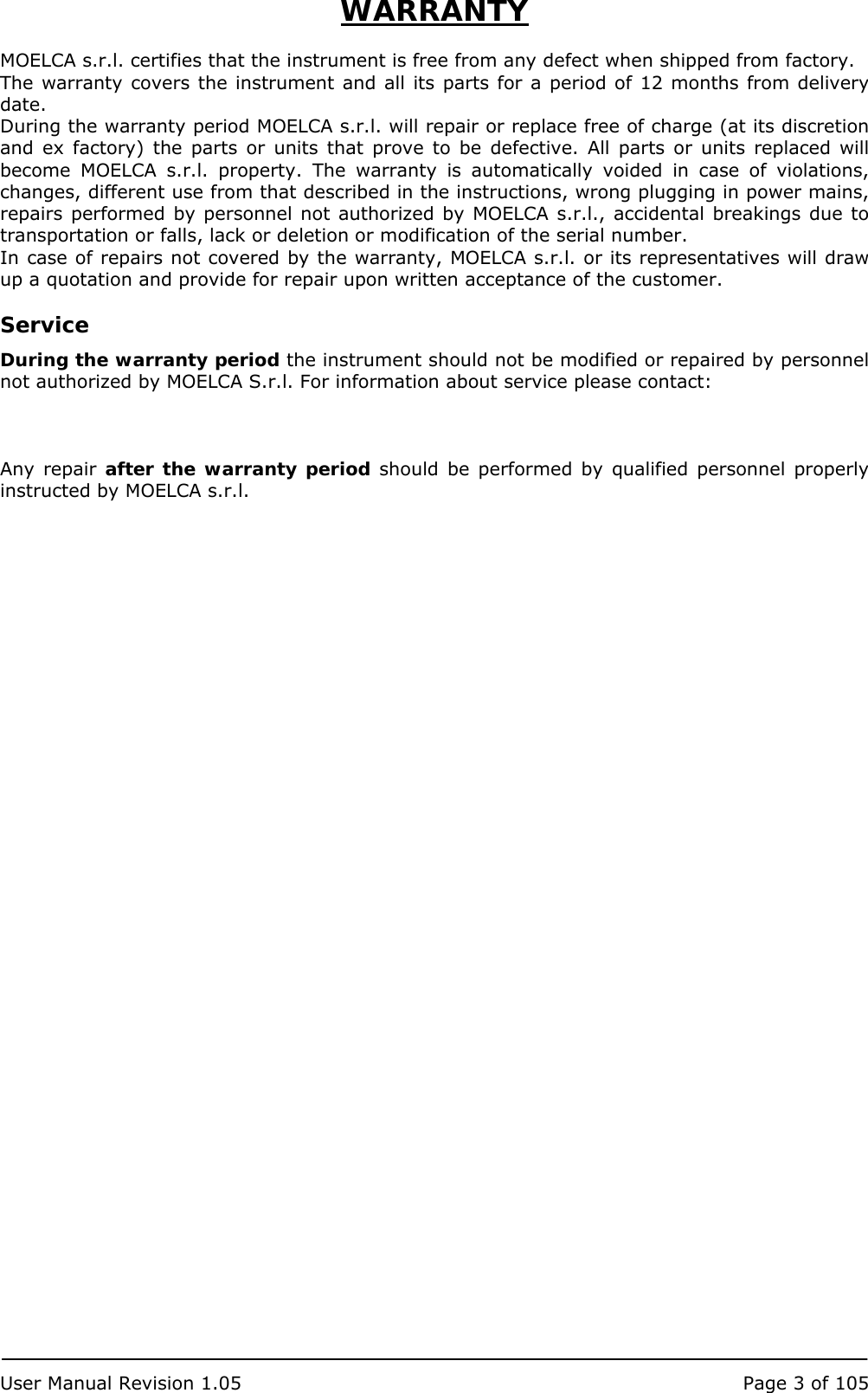
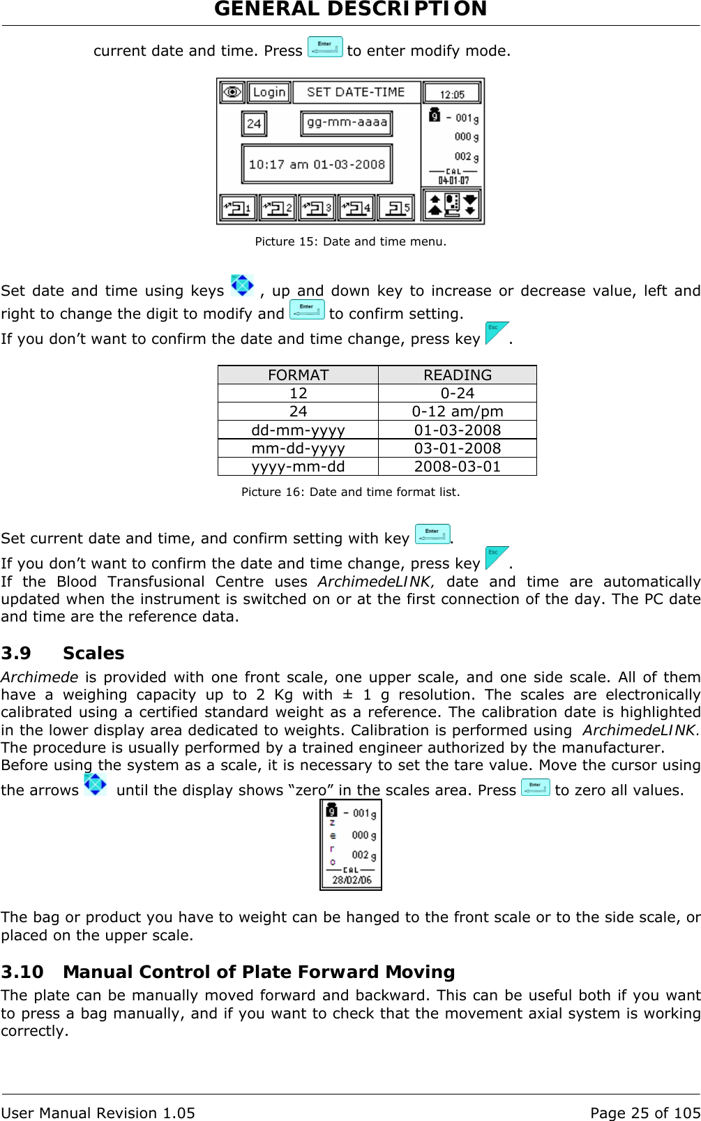
![GENERAL DESCRIPTION Page 22 of 105 User Manual Revision 1.05 6 NUMBER OF IR SENSOR USED TO ENABLE HB SENSOR: Number identifying the IR sensor dedicated to RBC sensor activation. RBC TARGET LEVEL: (PROCEDURE 8) Value of IR - HB sensor to intercept the level of RBC. 7 MINIMUM OPTICAL GAP BETWEEN RBC AND PLASMA: Value minimal of difference of reading between RBC and plasma with which it comes controlled the bag before and during the procedure. 8 HB SENSOR SENSIBILITY: Sensibility HB sensor. 10 IR SENSOR ACTION THRESHOLD: Threshold value for action of IR sensors. 15 NUMBER OF IR SENSOR USED FOR CHECK BUFFY COAT LEVEL: Decimal number identifying the IR sensor buffy coat level position. HAEMATOCRIT SELECTION: (PROCEDURE 13) Allows you to set the desired level of haematocrit, based on this value system displays the number of IR LED concerned. 26 CLAMP CLOSURE DELAY TIME AFTER ERYTHROCITES LEVEL DETECTION Delay time for clamp closure after detecting erythrocites level [0-25]s. 42 Air Elimination: Allows to enable or inhibit the air elimination routine from plasma. 47 SELECTION OF IR CORRESPONDING TO UPPER AND LOWER BAG SIDE: Allows to select the calibration sensors to be used to define the system’s optical sensitivity. For optimum operation of the optical system, always select sensors within lower and higher reflection area of the label. If this is not possible because the label is on both sides, select so that the sensors can detect both plasma and RBCs. Force management Parameters for the force regulation system during the procedure. 9 MAXIMUM FORCE: Value of the maximum force applied during the procedure; the plate stops if the force exceeds this limit. 13 MOTOR SPEED IN AUTOLEARNING PHASE: Plate moving speed used in the first phase for the management of force . Seal management Parameters the select witch clamps will seal and how the selected clamp will seal. 11 SEALING MODE: Selection of the sealing mode. In automatic mode, the system automatically seals the bags when the procedure is over. In manual mode, bags sealing must be confirmed. 12 SEALING CLAMPS SELECTION: Selection of clamps to be used for sealing when the procedure is over. Clamps are numbered as follows: 1 Top, 2 Plasma, 4 Buffy, 8 Bottom. The value to be set in this position is the value corresponding to the sum of the clamps used: for example, if bottom and top are to be used, the value to be set is 9. 40 Clamps Number: Value allowing to select the clamps to be used in the procedure. Maximum flow of Sag. M. supplied, beyond which the dispensing force decreases.](https://usermanual.wiki/MOELCA-S-R-L/1504/User-Guide-1140271-Page-22.png)
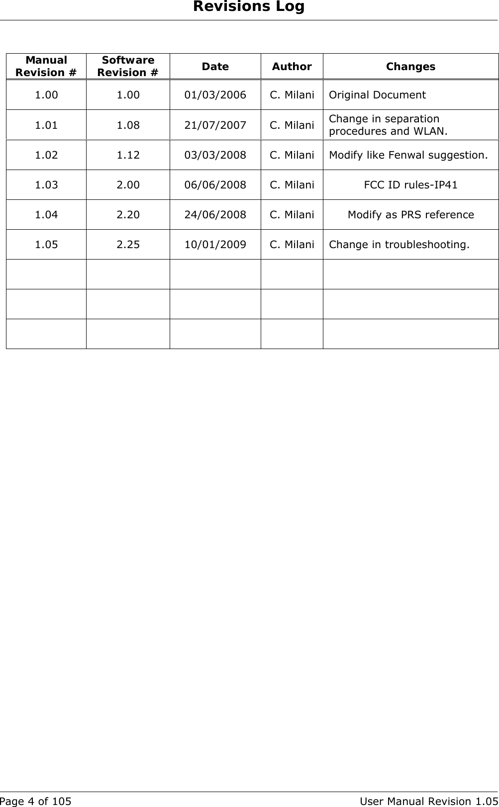
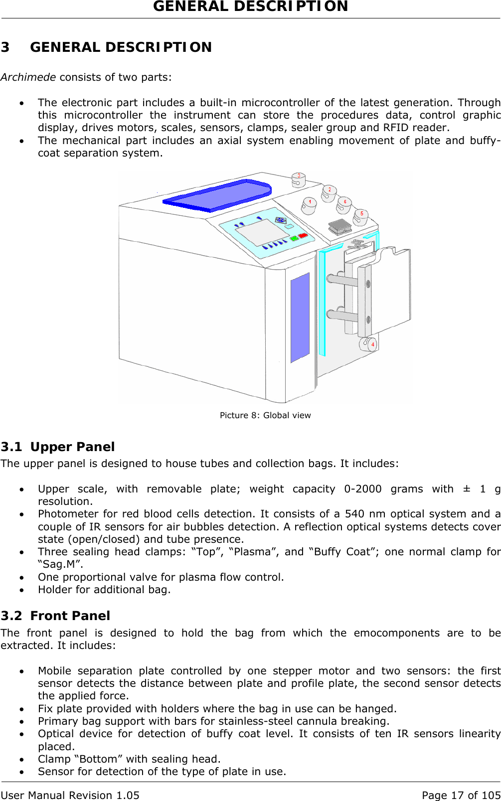
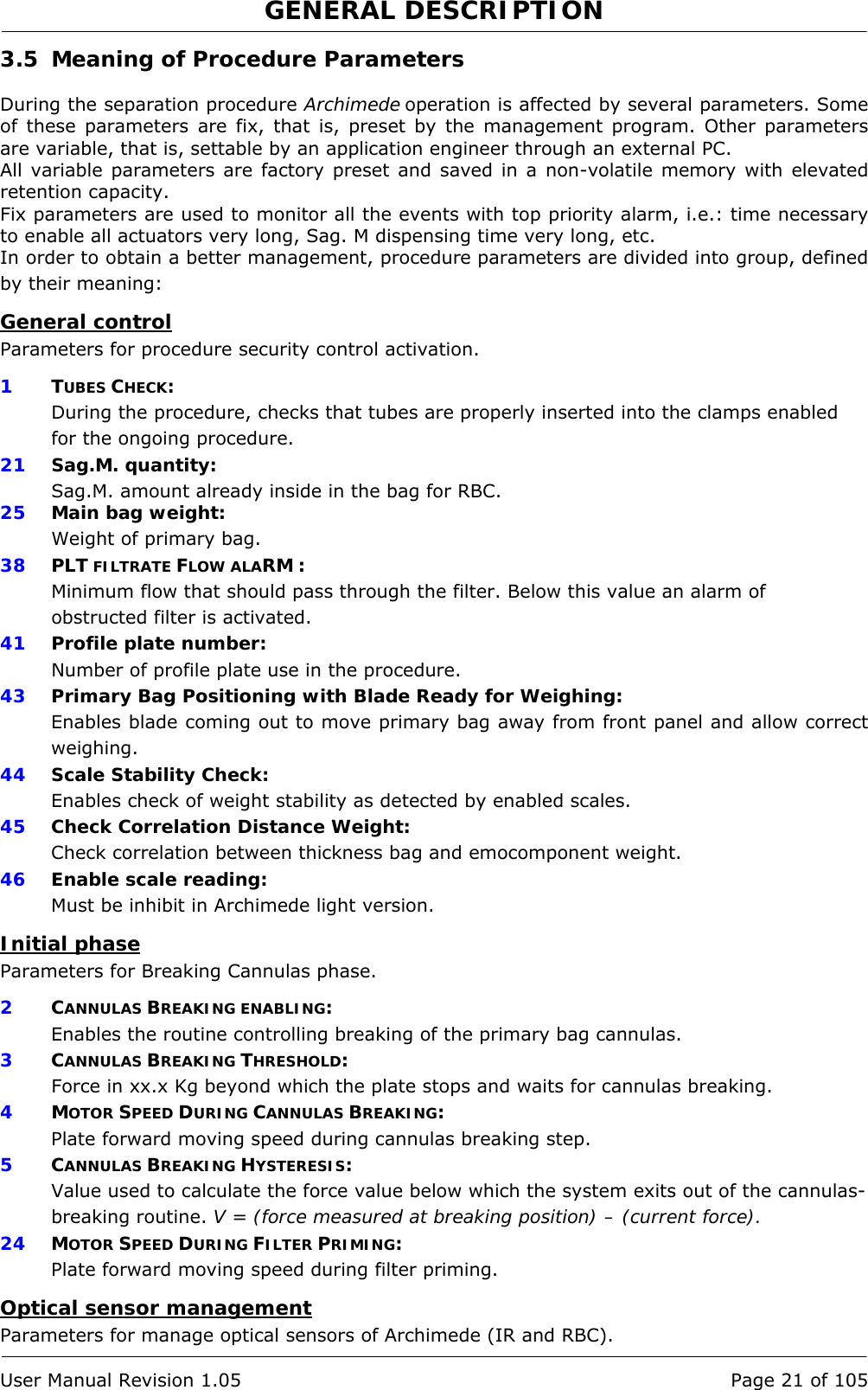
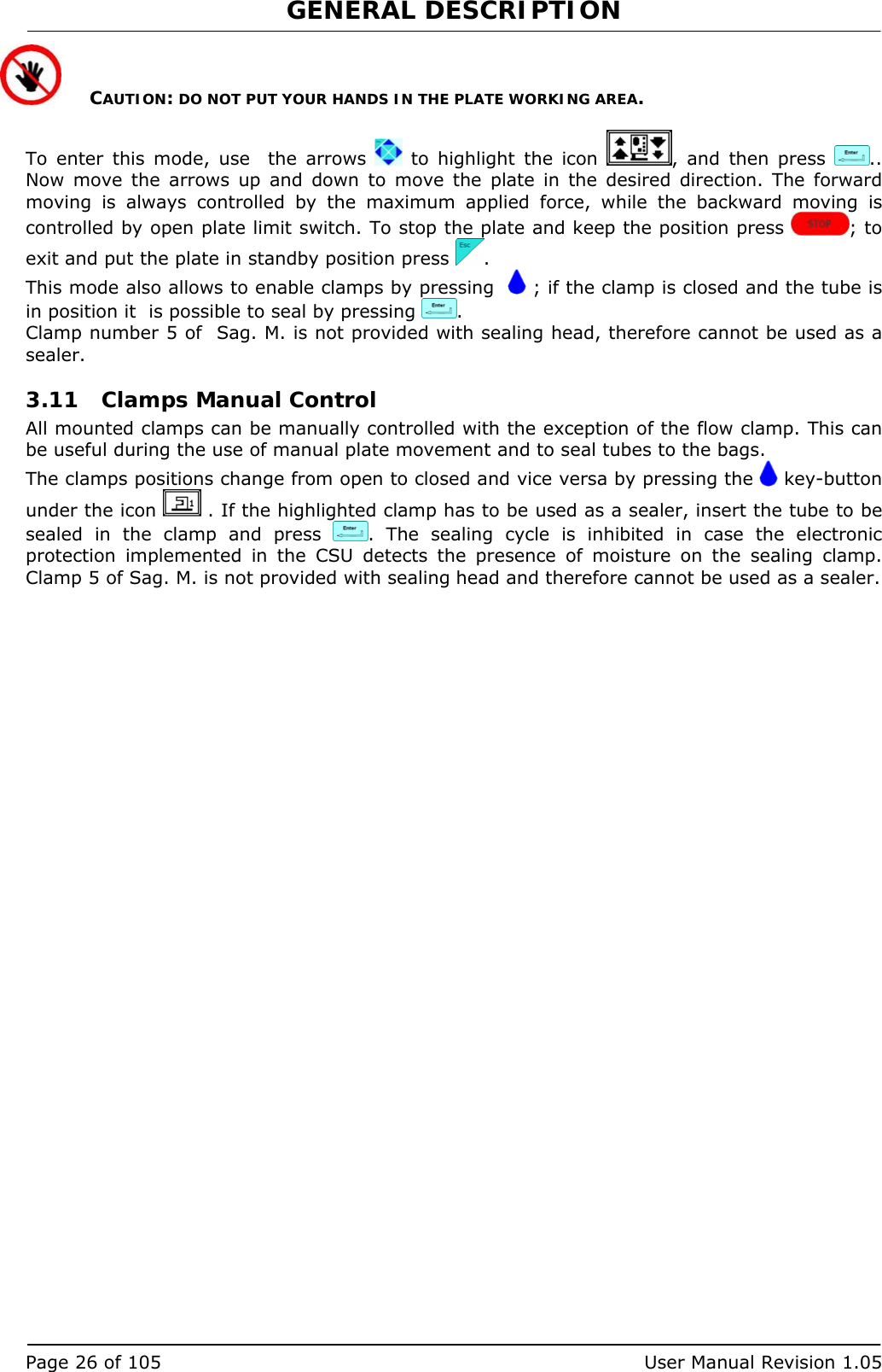
![GENERAL DESCRIPTION User Manual Revision 1.05 Page 23 of 105 Emocomponent volume Parameters that define the Buffy Coat and the Sag.M. target volume. 18 RBCS NOT DETECTED FINAL DISTANCE WARNING: Final distance value beyond which the system, after confirmation, stops the procedure if RBCs have not been detected. BUFFY COAT VOLUME: Desired buffy coat volume. INSUFFICIENT DISPENSED VOLUMES FINAL DISTANCE WARNING: Final distance value beyond which the system, after confirmation, stops the procedure if the set volumes have not been dispensed. 20 SAG. M. AMOUNT: Sag. M. in [g] to be dispensed in the final step of the procedure. 22 BUFFY COAT AMOUNT WITHOUT BLADE SEPARATION: Buffy coat [g] top be dispensed before mechanical blade separation. 23 BUFFY COAT ALARM DISTANCE: Value of the distance beyond which the system, after confirmation, stops the procedure if the desired buffy coat amount has not been collected. 29 ALIQUOT WEIGHT 1: ( UPPER SCALE) Weight 1 desired for aliquot separation procedure. 14 ALIQUOT 2 WEIGHT: (UPPER SCALE) Weight 2 desired for aliquot separation procedure. 30 PLASMA-PLT WEIGHT: Value of the amount of plasma-plt to be separated. 37 BUFFY COAT TOTAL WEIGHT: Total buffy coat weight. 39 ALIQUOT 3 WEIGHT: (LATERAL SCALE) Weight 3 desired for aliquot separation procedure. Secondary Emocomponent volume Parameters that define the auto recover, wash or dilution and aliquot separation target volume. 19 EXCESS PLASMA FOR FILTER: Excess plasma [g] to be collected after the system has detected the buffy coat. MANUAL DISPENSING: Enables manual platelets recovery after detecting RBCs. 32 SENSIBILITY OF FLOW VALVE: Adjust sensitivity of flow valve feedback. (Clamp 6) 34 PLASMA FOR BC DILUTION: Amount of plasma to be added to the buffy coat when its separator is enabled. 35 Delay for BUFFY COAT LINE CLEANING WITH SAG.M.: Delay for cleaning deviation of Buffy Coat line with Sag.M. 36 PLASMA AMOUNT FOR BUFFY COAT TUBE CLEANING: Amount of plasma to be dispensed by gravity in the buffy coat bag.](https://usermanual.wiki/MOELCA-S-R-L/1504/User-Guide-1140271-Page-23.png)
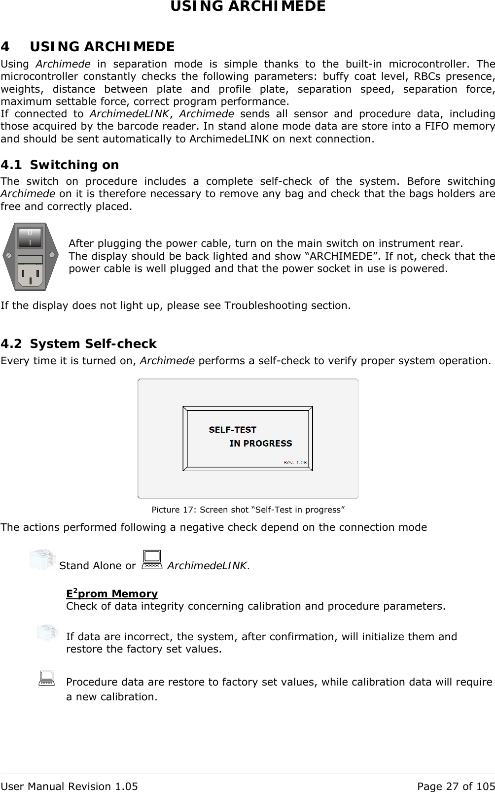
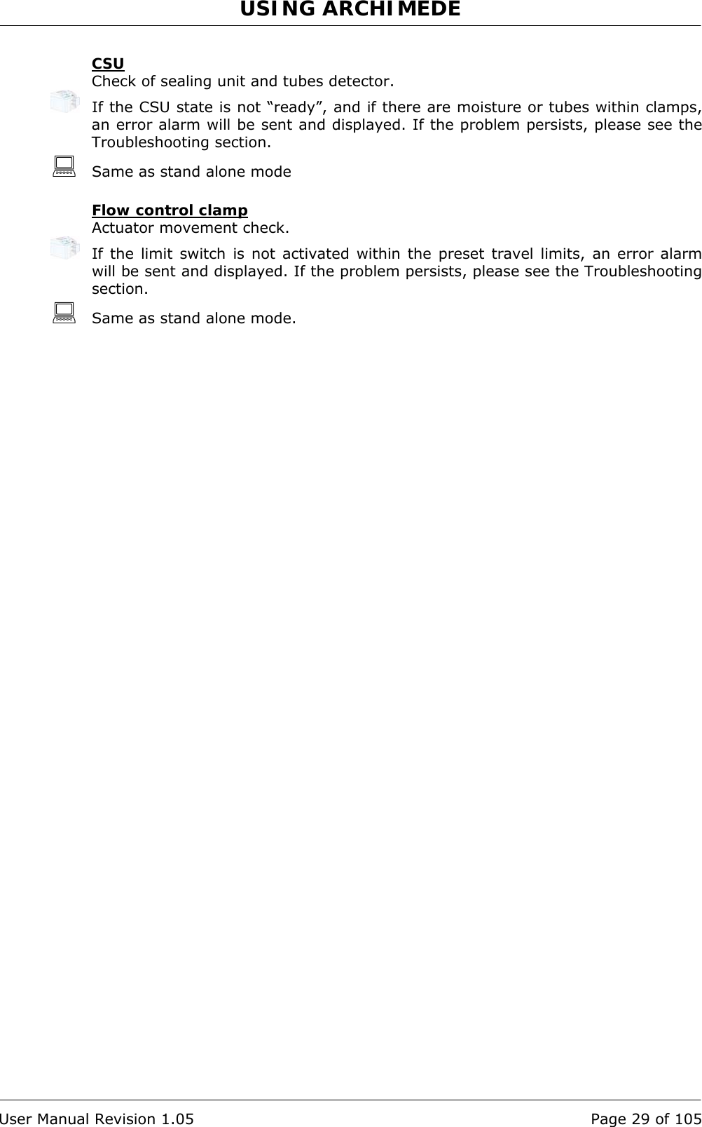
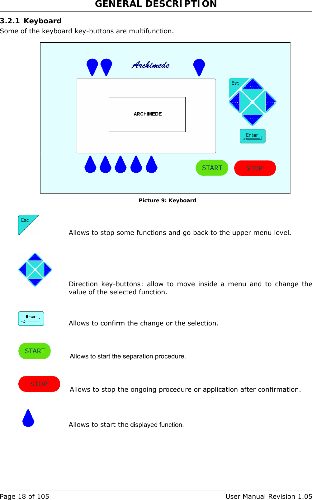
![USING ARCHIMEDE Page 30 of 105 User Manual Revision 1.05 4.3 Use as a scale Archimede can be used as a weighing system thanks to its three load cells. The maximum measurable weight is 2 Kg with 1 g resolution. Before using the system as a scale, it is necessary to calculate the tare. Move the cursor using the arrows until the word “zero” is displayed in the scales area of the screen and press to zero the values. Picture 18: Scale tare Now use the arrows to move the cursor to another option; this will avoid performing another tare by pressing key-button unintentionally Take the product you wish to weigh and hang it to the front or side scale, or put it on the upper scale. Weights are displayed in the following order: Picture 19: Reading scale area 4.4 Use as a sealing unit Archimede can be used as a sealing unit thanks to its four built-in sealing heads. Press key-button below the sealing head that you wish to use or highlight the sealing head using the arrows . Location of the sealing heads is as follows: Picture 20: Archimede view [4] SEALING HEAD[3] SEALING HEAD[2] SEALING HEAD[1] SEALING HEAD[5] NON-SEALING HEAD Front scale Upper scale Side scale](https://usermanual.wiki/MOELCA-S-R-L/1504/User-Guide-1140271-Page-30.png)
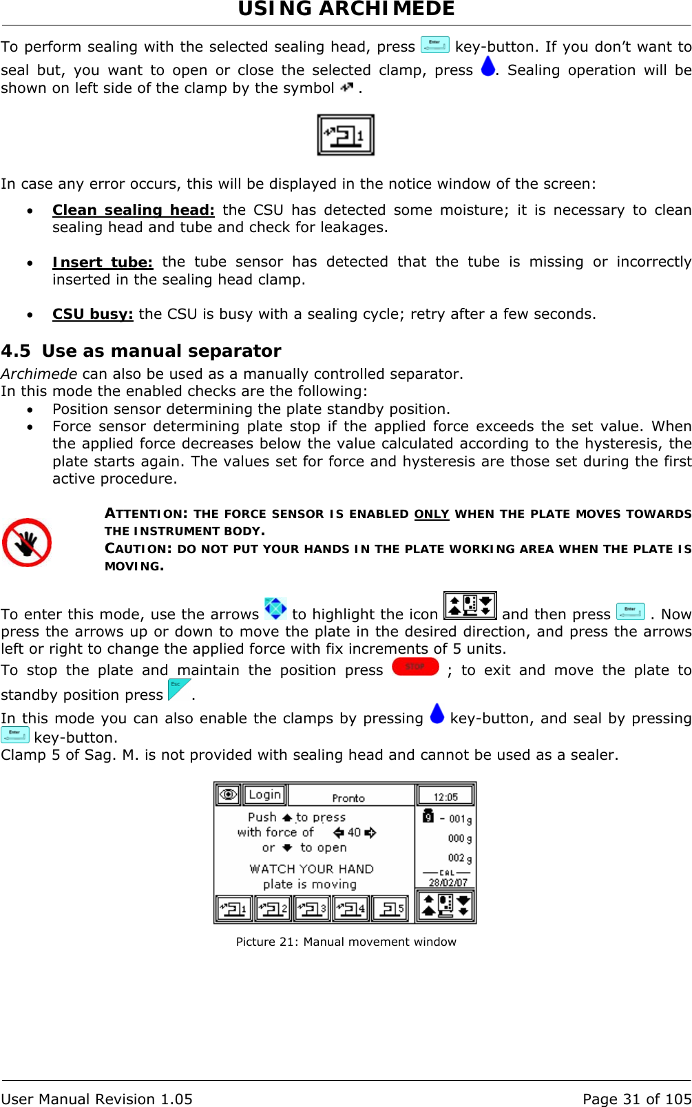
![USING ARCHIMEDE Page 32 of 105 User Manual Revision 1.05 4.6 Separation Procedure Archimede can store up to 18 procedures. The operator can perform a manual selection or an automatic selection if the system is connected to ArchimedeLINK. • Manual mode: To speed up procedures selection, the system can be configured to show only the procedures enabled. In this way, only the procedures most frequently used in the blood transfusional center will be displayed. Using the arrows highlight the procedure you intend to use, then press to start the procedure. Picture 22: Enable procedures list • Automatic mode: Using ArchimedeLINK it is possible to associate a bag type to a procedure type. In this way, from the main menu you will only have to read the bag type barcode and ArchimedeLINK will transmit to Archimede what type of procedure it has to run. The separation procedures presently available are: PRIMARY # 1 T & T triple PPP or PRP + RCC. # 2 T & T quadruple PPP or PRP BC + RCC. # 3 Top & Bottom triple PPP+BC+RCC. # 4 Top & Bottom quadruple PPP+BC+RCC. # 10 [a] Cord separation. # 11 [b] Aliquot separation. # 13 [d] Procedure Top & Top RBC with PPP + PPP. SECONDARY # 5 PPP + PLT. # 7 PLT + residual BC with filter. # 8 Erythrocytes washing separation.](https://usermanual.wiki/MOELCA-S-R-L/1504/User-Guide-1140271-Page-32.png)
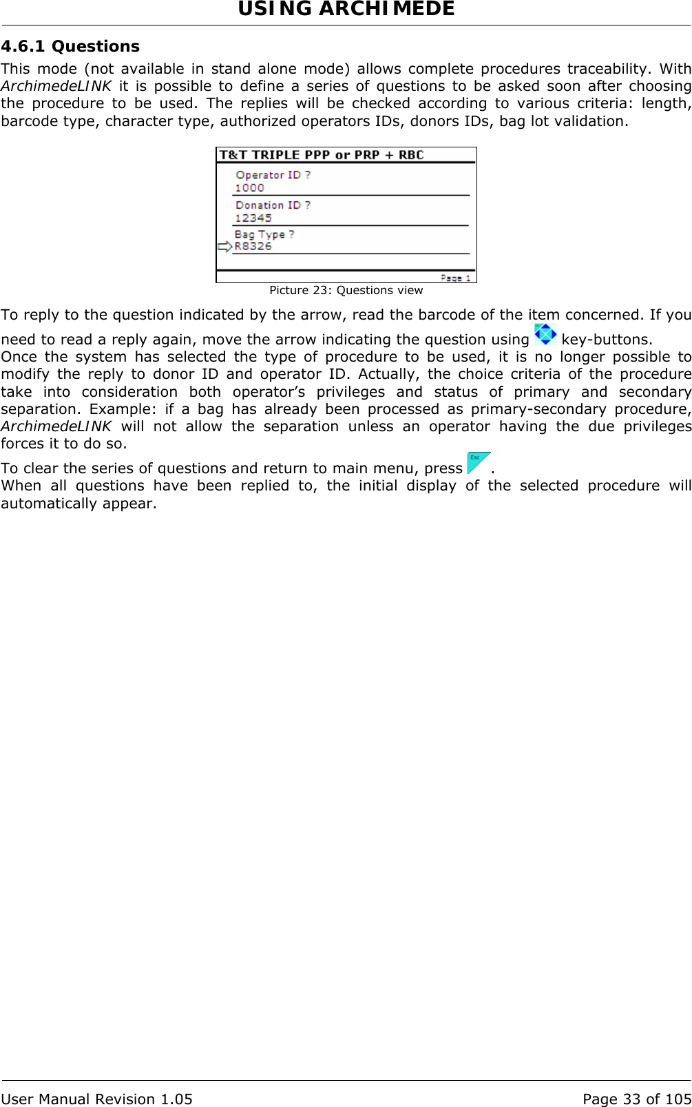
![USING ARCHIMEDE Page 34 of 105 User Manual Revision 1.05 4.6.2 PROCEDURE 1 T & T triple PPP or PRP + RCC. This procedure is suitable for triple bags containing Sag. M. It allows erythrocytes separation (RCC) and platelets poor plasma (PPP). Parameters used: 1 During the procedure, checks that tubes are properly inserted into the clamps enabled for the ongoing procedure. 2 Enables the routine controlling breaking of the primary bag cannulas. 3 Force in xx.x Kg beyond which the plate stops and waits for cannulas breaking. 4 Plate forward moving speed during cannulas breaking step. 5 Value used to calculate the force value below which the systems exits the cannulas breaking routine. V =(force measured at breaking position) – (current force). 6 Number identifying the IR sensor dedicated to RBC sensor enabling. 7 Value minimal of difference of reading between RBC and plasma with which it comes controlled the bag before and during the procedure 8 Sensibility HB sensor. 9 Value of the maximum force applied during the procedure; the plate stops if the force exceeds this limit. 11 Selection of the sealing mode. In automatic mode, the system automatically seals the bags when the procedure is over. In manual mode, bags sealing must be confirmed. 12 Selection of clamps to be used for sealing when the procedure is over. Clamps are numbered as follows: 1 Top, 2 Plasma, 4 Buffy, 8 Bottom. The value to be set in this position is the value corresponding to the sum of the clamps used: for example, if bottom and top are to be used, the value to be set is 9. 13 Plate moving speed used in the first phase for the management of force 18 Value of the distance beyond which the system, after confirmation, stops the procedure if no RBCs have been detected. 19 Excess plasma [g] to be collected after the system has detected the buffy coat. 20 Sag. M. amount [g] to be dispensed in the final step of procedure. 25 Tara sacca primaria. Valore utilizzato per calcolare la quantità di prodotto rimasto nella sacca primaria. [peso attuale-tara] 26 Threshold value used to detect air bubbles during procedures requiring its elimination. 40 Value allowing to select the clamps to be used in the procedure. 41 Number of the profile plate to be used with the ongoing procedure. 42 Enables the air elimination routine. 43 Primary bag positioning with blade ready for weighing. 44 Scale stability check. 45 Check Correlation Distance Weight. 46 Enable scale reading. 47 IR corresponding to higher and lower bag edge.](https://usermanual.wiki/MOELCA-S-R-L/1504/User-Guide-1140271-Page-34.png)
![USING ARCHIMEDE User Manual Revision 1.05 Page 39 of 105 4.6.3 PROCEDURE 2 T & T quadruple PPP or PRP BC + RCC. This procedure is suitable for quadruple bags containing Sag. M. It allows to separate erythrocytes (RCC), platelets poor plasma (PPP) and buffy coat. Parameters used: 1 During the procedure, checks that tubes are properly inserted into the clamps enabled for the ongoing procedure. 2 Enables the routine controlling breaking of the primary bag cannulas. 3 Force in xx.x Kg beyond which the plate stops and waits for cannulas breaking. 4 Plate forward moving speed during cannulas breaking step. 5 Value used to calculate the force value below which the systems exits the cannulas breaking routine. V =(force measured at breaking position) – (current force). 6 Number identifying the IR sensor dedicated to RBC sensor enabling. 7 Value minimal of difference of reading between RBC and plasma with which it comes controlled the bag before and during the procedure 8 Sensibility HB sensor. 9 Value of the maximum force applied during the procedure; the plate stops if the force exceeds this limit. 11 Selection of the sealing mode. In automatic mode, the system automatically seals the bags when the procedure is over. In manual mode, bags sealing must be confirmed. 12 Selection of clamps to be used for sealing when the procedure is over. Clamps are numbered as follows: 1 Top, 2 Plasma, 4 Buffy, 8 Bottom. The value to be set in this position is the value corresponding to the sum of the clamps used: for example, if bottom and top are to be used, the value to be set is 9. 13 Plate moving speed used in the first phase for the management of force. 16 Plasma to dilute Buffy Coat. 18 Value of the distance beyond which the system, after confirmation, stops the procedure if no RBCs have been detected. 19 Excess plasma [g] to be collected after the system has detected the buffy coat. 20 Sag. M. amount [g] to be dispensed in the final step of procedure. 22 Buffy coat amount [g] to be dispensed before mechanical separation. 23 Value of the distance beyond which the system, after confirmation, stops the procedure if the desired buffy coat amount has not been collected. 25 Tare of the primary bag. This value is used to calculate the product amount left in the primary bag. [current weight - tare] 34 Amount of plasma to be dispensed in the buffy coat bag. 35 Delay for cleaning deviation of Buffy Coat line with Sag.M. 36 Amount of plasma to be dispensed by gravity in the buffy coat bag. 40 Value allowing to select the clamps to be used in the procedure. 41 Number of the profile plate to be used with the ongoing procedure. 42 Enabling of the air elimination routine. 43 Primary bag positioning with blade ready for weighing. 44 Scale stability check. 45 Check Correlation Distance Weight. 46 Enable scale reading. 47 IR corresponding to upper and lower bag edges.](https://usermanual.wiki/MOELCA-S-R-L/1504/User-Guide-1140271-Page-39.png)
![USING ARCHIMEDE Page 44 of 105 User Manual Revision 1.05 4.6.4 PROCEDURE 3 Top & Bottom triple PPP+BC+RCC. This procedure is indicated for triple top & bottom bags to obtain buffy coat (BC), erythrocytes (RCC) and plasma (PRP). Parameters used: 1 During the procedure, checks that tubes are properly inserted into the clamps enabled for the ongoing procedure. 2 Enables the routine controlling breaking of the primary bag cannulas. 3 Force in xx.x Kg beyond which the plate stops and waits for cannulas breaking. 4 Plate forward moving speed during cannulas breaking step. 5 Value used to calculate the force value below which the systems exits the cannulas breaking routine. V =(force measured at breaking position) – (current force). 7 Value minimal of difference of reading between RBC and plasma with which it comes controlled the bag before and during the procedure 8 Sensibility HB sensor. 9 Value of the maximum force applied during the procedure; the plate stops if the force exceeds this limit. 11 Selection of the sealing mode. In automatic mode, the system automatically seals the bags when the procedure is over. In manual mode, bags sealing must be confirmed. 12 Selection of clamps to be used for sealing when the procedure is over. Clamps are numbered as follows: 1 Top, 2 Plasma, 4 Buffy, 8 Bottom. The value to be set in this position is the value corresponding to the sum of the clamps used: for example, if bottom and top are to be used, the value to be set is 9. 13 Plate moving speed used in the first phase for the management of force 15 Number identifying the IR sensor dedicated to buffy coat level. 18 Buffy coat target value. 20 Sag. M. amount [g] to be dispensed in the final step of the procedure. 21 Sag.M. amount already present in RBC destination bag. 25 Tare of the primary bag. This value is used to calculate the product amount left in the primary bag. [current weight - tare]. 32 Sensibility flow valve. (Clamp 6) 36 Plasma amount to be dispensed in the buffy coat bag. 40 Value allowing to select the clamps to be used in the procedure. 41 Number of the profile plate to be used with the ongoing procedure. 42 Enables the air elimination routine. 43 Primary bag positioning with blade ready for weighing. 44 Scale stability check. 45 Check Correlation Distance Weight. 46 Enable scale reading. 47 IR corresponding to upper and lower bag edges.](https://usermanual.wiki/MOELCA-S-R-L/1504/User-Guide-1140271-Page-44.png)
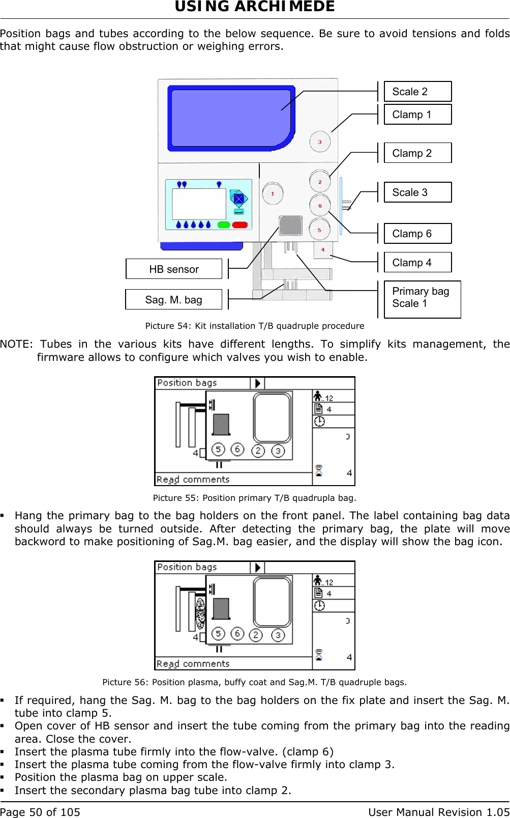
![USING ARCHIMEDE User Manual Revision 1.05 Page 49 of 105 4.6.5 PROCEDURE 4 Top & Bottom quadruple PPP+BC+RCC. This procedure is indicated for quadruple top & bottom bags to obtain buffy coat (BC), erythrocytes (RCC) and two plasma (PPP) one PPP for single buffy coat. Parameters used: 1 During the procedure, checks that tubes are properly inserted into the clamps enabled for the ongoing procedure. 2 Enables the routine controlling breaking of the primary bag cannulas. 3 Force in xx.x Kg beyond which the plate stops and waits for cannulas breaking. 4 Plate forward moving speed during cannulas breaking step. 5 Value used to calculate the force value below which the systems exits the cannulas breaking routine. V =(force measured at breaking position) – (current force). 7 Value minimal of difference of reading between RBC and plasma with which it comes controlled the bag before and during the procedure 8 Sensibility HB sensor. 9 Value of the maximum force applied during the procedure; the plate stops if the force exceeds this limit. 11 Selection of the sealing mode. In automatic mode, the system automatically seals the bags when the procedure is over. In manual mode, bags sealing must be confirmed. 12 Selection of clamps to be used for sealing when the procedure is over. Clamps are numbered as follows: 1 Top, 2 Plasma, 4 Buffy, 8 Bottom. The value to be set in this position is the value corresponding to the sum of the clamps used: for example, if bottom and top are to be used, the value to be set is 9. 13 Plate moving speed used in the first phase for the management of force. 15 Number identifying the IR sensor dedicated to buffy coat level. 18 Buffy coat target value. 20 Sag. M. amount [g] to be dispensed in the final step of procedure. 21 Sag.M. amount already present in RBC destination bag. 25 Tare of the primary bag. This value is used to calculate the product amount left in the primary bag [current weight - tare]. 32 Flow valve sensibility. (Clamp 6) 34 Plasma amount to be added to second plasma bag. 36 Plasma amount to be dispensed by gravity in the buffy coat bag. 40 Value allowing to select the clamps to be used in the procedure. 41 Number of the profile plate to be used with the ongoing procedure. 42 Enables the air elimination routine. 43 Primary bag positioning with blade ready for weighing. 44 Scale stability check. 45 Check Correlation Distance Weight. 46 Enable scale reading. 47 IR corresponding to upper and lower bag edges.](https://usermanual.wiki/MOELCA-S-R-L/1504/User-Guide-1140271-Page-49.png)
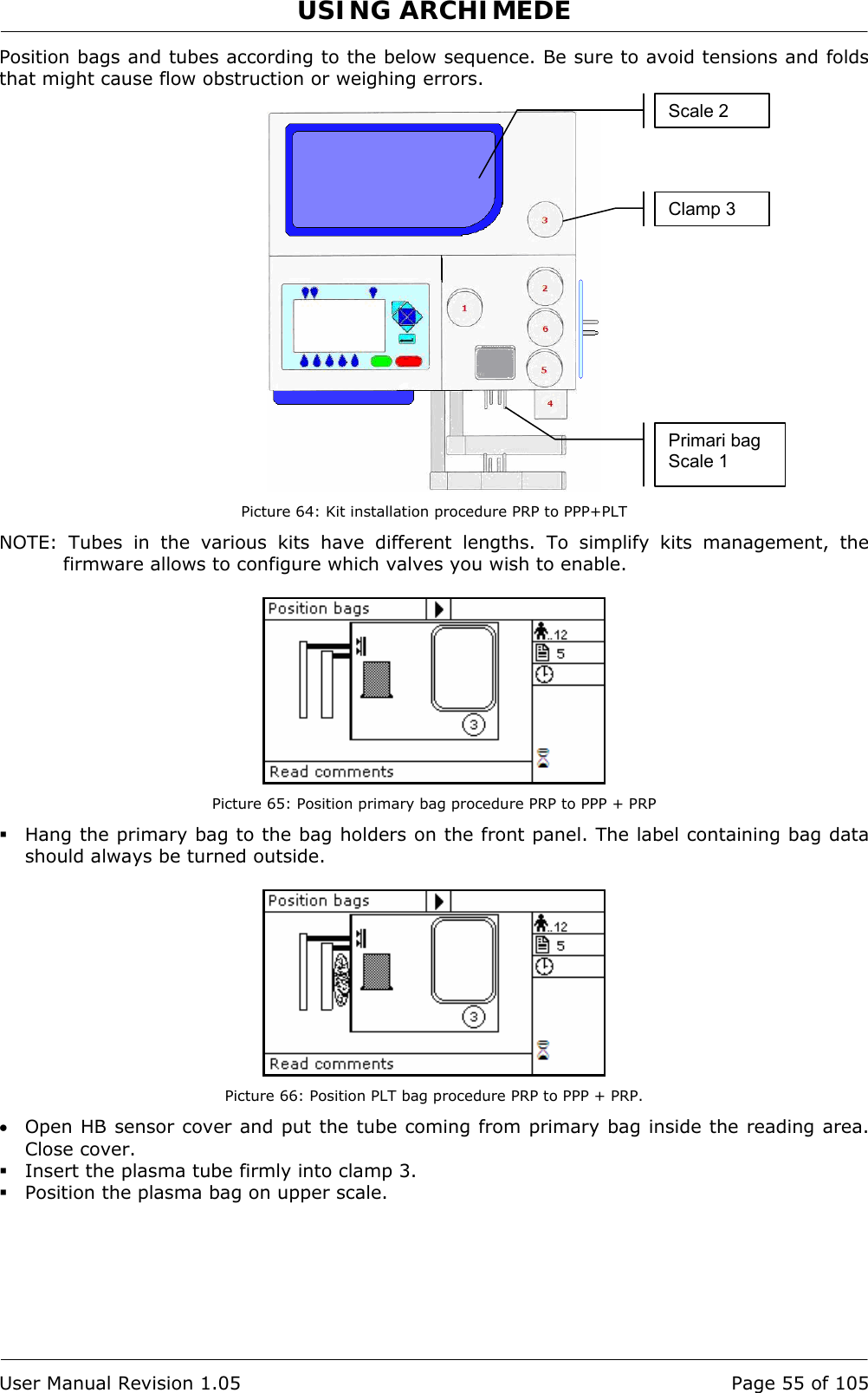
![USING ARCHIMEDE Page 54 of 105 User Manual Revision 1.05 4.6.6 PROCEDURE 5 Separation from PRP to PPP+PLT This secondary procedure is for separate from PRP to result platelets poor plasma (PPP), and platelets concentrate. Parameters used: 1 During the procedure, checks that tubes are properly inserted into the clamps enabled for the ongoing procedure. 2 Enables the routine controlling breaking of the primary bag cannulas. 3 Force in xx.x Kg beyond which the plate stops and waits for cannulas breaking. 4 Plate forward moving speed during cannulas breaking step. 5 Value used to calculate the force value below which the systems exits the cannulas breaking routine. V =(force measured at breaking position) – (current force). 9 Value of the maximum force applied during the procedure; the plate stops if the force exceeds this limit. 11 Selection of the sealing mode. In automatic mode, the system automatically seals the bags when the procedure is over. In manual mode, bags sealing must be confirmed. 12 Selection of clamps to be used for sealing when the procedure is over. Clamps are numbered as follows: 1 Top, 2 Plasma, 4 Buffy, 8 Bottom. The value to be set in this position is the value corresponding to the sum of the clamps used: for example, if bottom and top are to be used, the value to be set is 9. 13 Plate moving speed used in the first phase for the management of force. 18 Value of the final distance beyond which the procedure stops. 25 Tare of primary bag. This value is used to calculate the product amount left in the primary bag [current weight - tare]. 30 Plasma-plt weight. 40 Value allowing to select the clamps to be used in the procedure 41 Number of the profile plate to be used with the ongoing procedure. 42 Enables the air elimination routine. 43 Primary bag positioning with blade ready for weighing. 44 Scale stability check. 45 Check Correlation Distance Weight. 46 Enable scale reading. 47 IR coresponding to upper and lower bag edge.](https://usermanual.wiki/MOELCA-S-R-L/1504/User-Guide-1140271-Page-54.png)
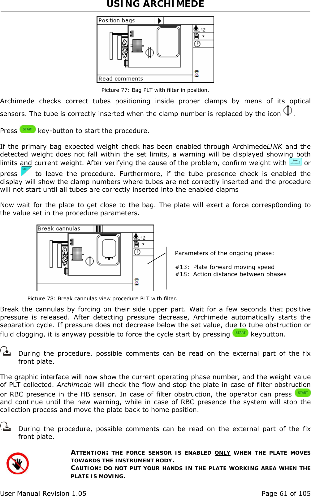
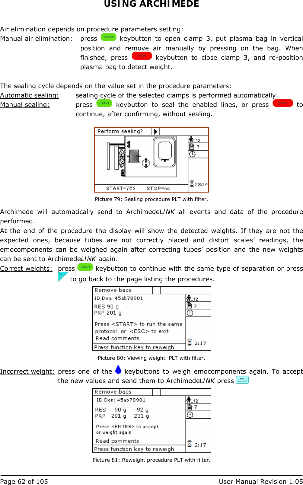
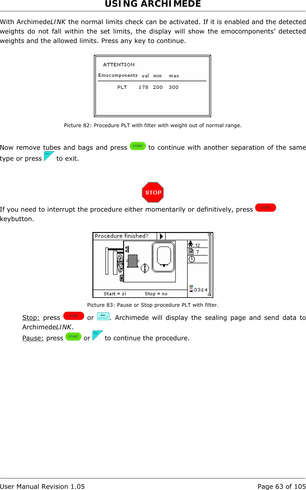
![USING ARCHIMEDE User Manual Revision 1.05 Page 59 of 105 4.6.7 PROCEDURE 7 Single or Pool of Buffy for PLT + residual BC with filter This procedure allows to collect platelets and filtrate. Parameters used: 1 During the procedure, checks that tubes are properly inserted into the clamps enabled for the ongoing procedure. 2 Enables the routine controlling breaking of the primary bag cannulas. 3 Force in xx.x Kg beyond which the plate stops and waits for cannulas breaking. 4 Plate forward moving speed during cannulas breaking step. 5 Value used to calculate the force value below which the systems exits the cannulas breaking routine. V =(force measured at breaking position) – (current force). 6 Number identifying the IR sensor dedicated to RBC sensor enabling. 8 Sensibility HB sensor. 9 Value of the maximum force applied during the procedure; the plate stops if the force exceeds this limit. 10 Threshold value for action of IR sensors. 11 Selection of the sealing mode. In automatic mode, the system automatically seals the bags when the procedure is over. In manual mode, bags sealing must be confirmed. 12 Selection of clamps to be used for sealing when the procedure is over. Clamps are numbered as follows: 1 Top, 2 Plasma, 4 Buffy, 8 Bottom. The value to be set in this position is the value corresponding to the sum of the clamps used: for example, if bottom and top are to be used, the value to be set is 9. 13 Plate moving speed used in the first phase for the management of force. 18 Value of the distance beyond which the system, after confirmation, stops the procedure if no RBCs have been detected. 19 Excess plasma [g] to be dispensed after the HB sensor has detected RBCs. If manual dispensing is enabled, the system allows manual product dispensing. 24 Motor speed during filter priming. 25 Tare of the primary bag. This value is used to calculate the product amount left in the primary bag [current weight - tare] 38 Minimum flow that should pass through the filter. Below this value an alarm of obstructed filter is activated. 40 Value allowing to select the clamps to be used in the procedure. 41 Number of the profile plate to be used with the ongoing procedure. 42 Enables the air elimination routine. 43 Primary bag positioning with blade ready for weighing. 44 Scale stability check. 45 Check Correlation Distance Weight. 46 Enable scale reading. 47 IR corresponding to upper and lower bag edge.](https://usermanual.wiki/MOELCA-S-R-L/1504/User-Guide-1140271-Page-59.png)
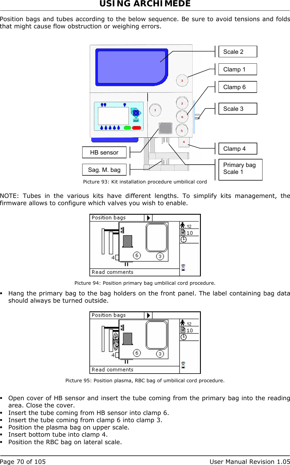
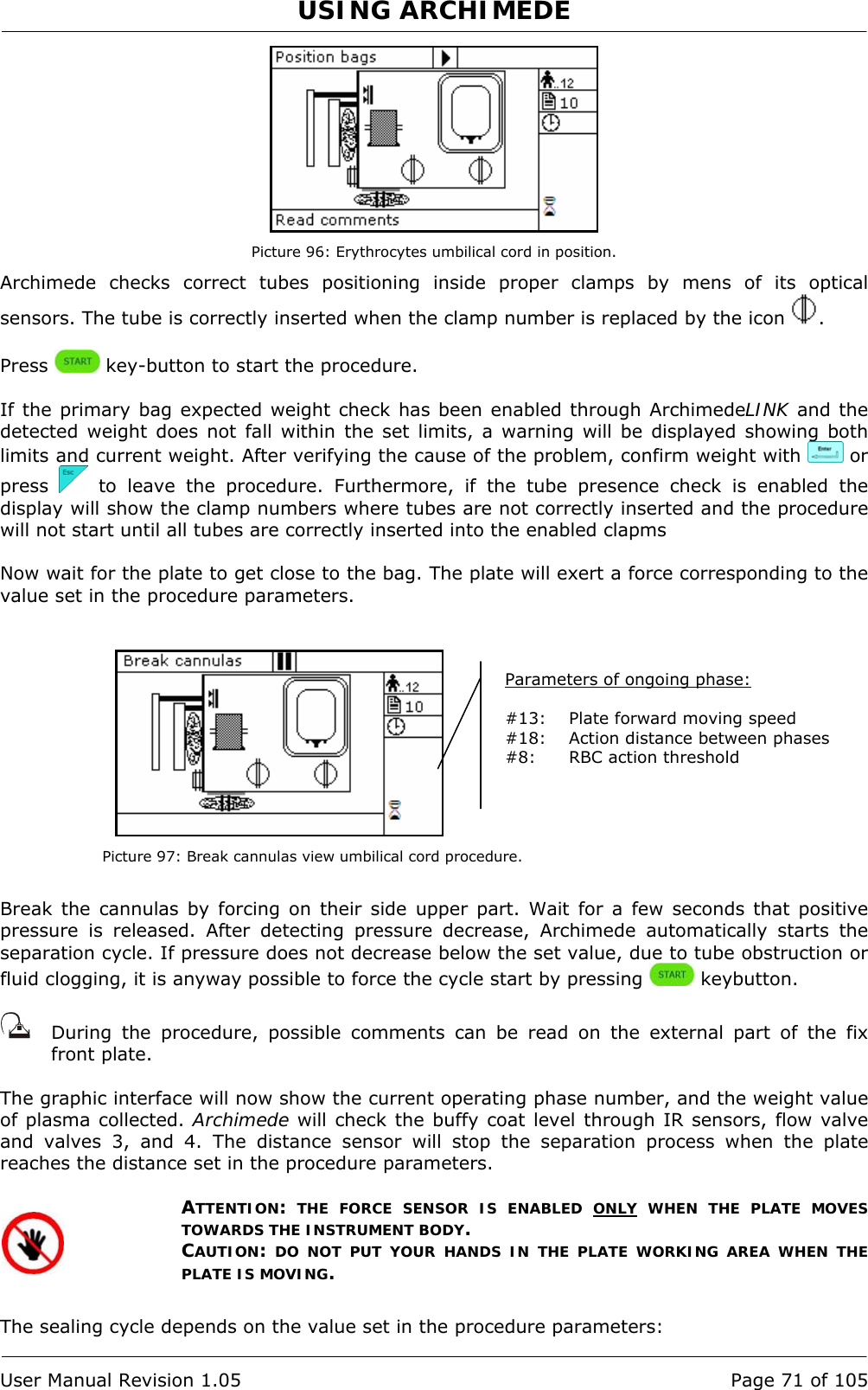
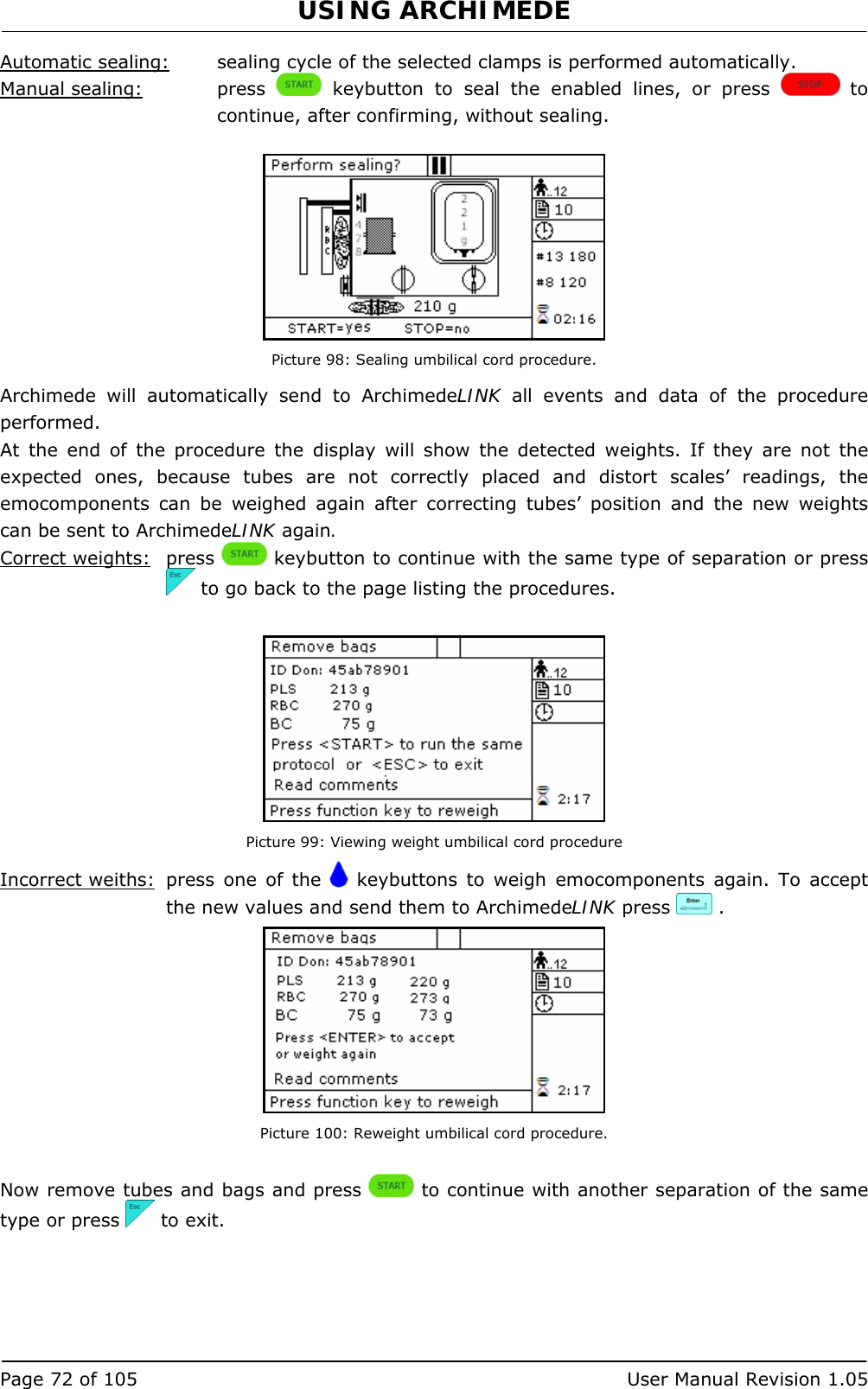
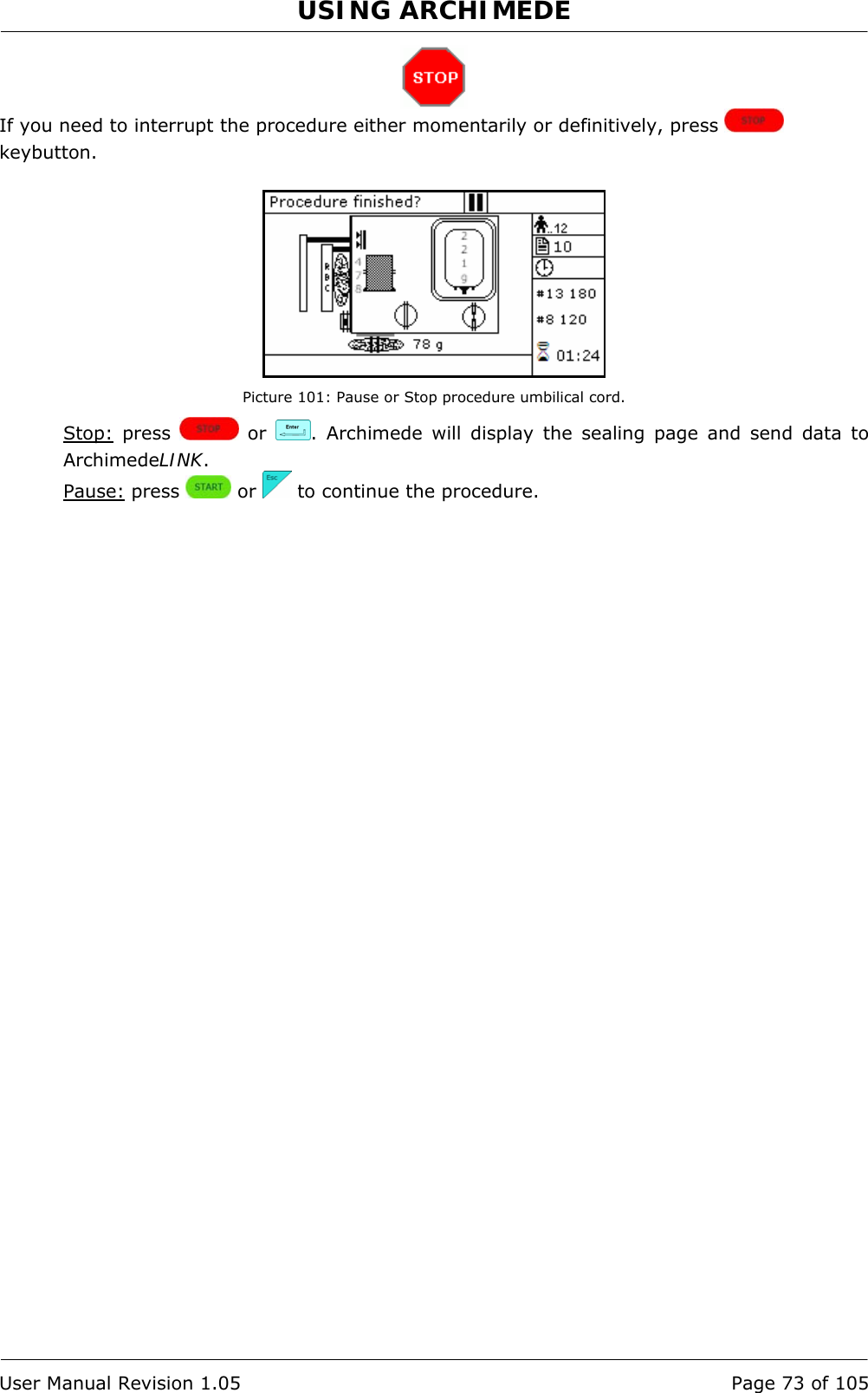
![USING ARCHIMEDE User Manual Revision 1.05 Page 69 of 105 4.6.9 PROCEDURE 10 [a]UMBILICAL CORD This procedure is indicated for quadruple top & bottom bag to obtain erythrocytes (RCC), plasma (PPP), and buffy coat (BC) diluted with plasma added through a press. Parameters used: 1 During the procedure, checks that tubes are properly inserted into the clamps enabled for the ongoing procedure. 2 Enables the routine controlling breaking of the primary bag cannulas. 3 Force in xx.x Kg beyond which the plate stops and waits for cannulas breaking. 4 Plate forward moving speed during cannulas breaking step. 5 Value used to calculate the force value below which the systems exits the cannulas breaking routine. V =(force measured at breaking position) – (current force). 7 Value minimal of difference of reading between RBC and plasma with which it comes controlled the bag before and during the procedure. 8 Sensibility HB sensor. 9 Value of the maximum force applied during the procedure; the plate stops if the force exceeds this limit. 11 Selection of the sealing mode. In automatic mode, the system automatically seals the bags when the procedure is over. In manual mode, bags sealing must be confirmed. 12 Selection of clamps to be used for sealing when the procedure is over. Clamps are numbered as follows: 1 Top, 2 Plasma, 4 Buffy, 8 Bottom. The value to be set in this position is the value corresponding to the sum of the clamps used: for example, if bottom and top are to be used, the value to be set is 9. 13 Plate moving speed used in the first phase for the management of force. 15 Number identifying the IR sensor dedicated to buffy coat level. 18 Buffy coat target value. 25 Tare of the primary bag. This value is used to calculate the product amount left in the primary bag [current weight - tare] 32 Sensibility flow valve. (Clamp 6) 40 Value allowing to select the clamps to be used in the procedure. 41 Number of the profile plate to be used with the ongoing procedure. 42 Enables the air elimination routine. 43 Primary bag positioning with blade ready for weighing. 44 Scale stability check. 45 Check Correlation Distance Weight. 46 Enable scale reading. 47 IR corresponding to upper and lower bag edges.](https://usermanual.wiki/MOELCA-S-R-L/1504/User-Guide-1140271-Page-69.png)
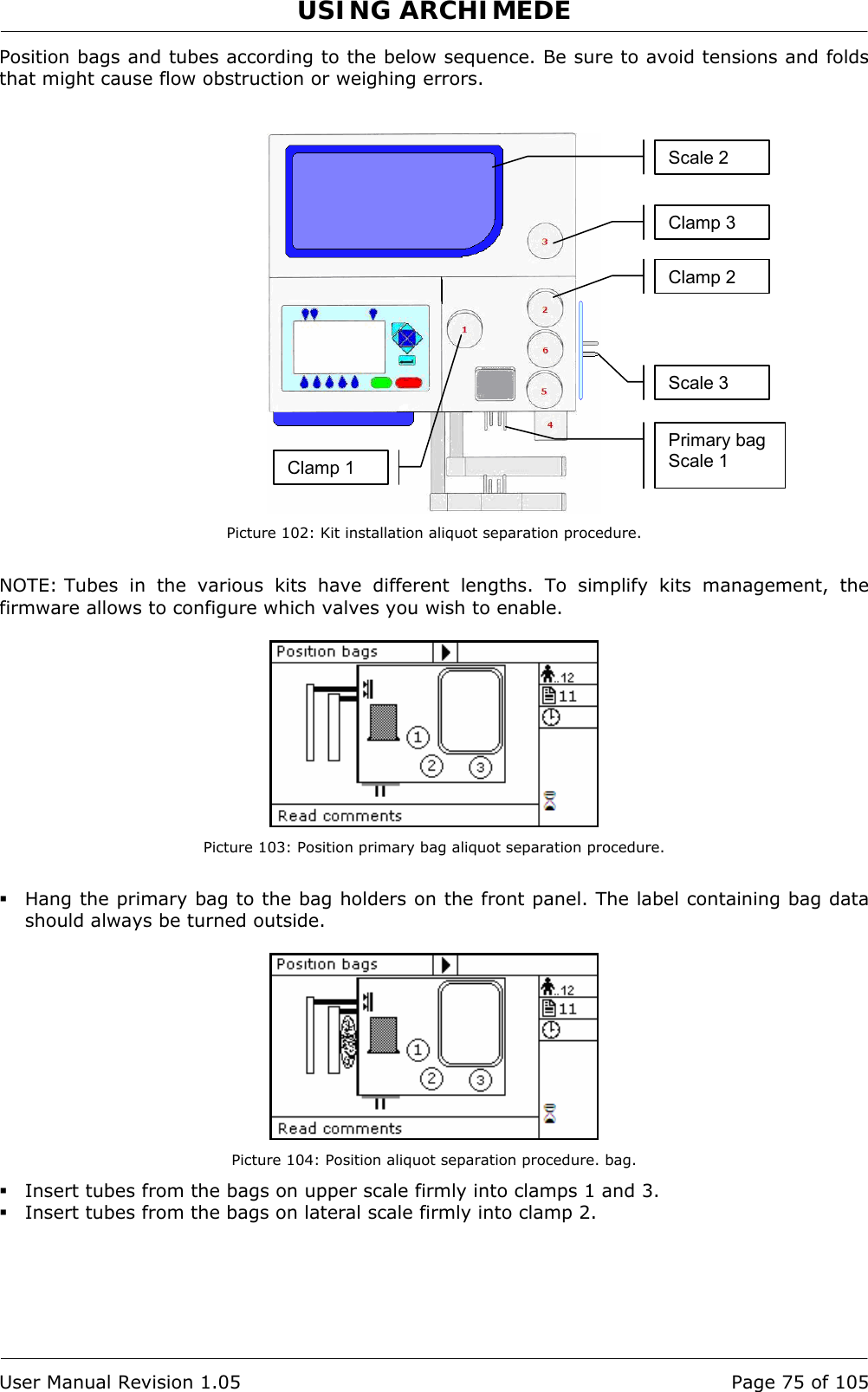
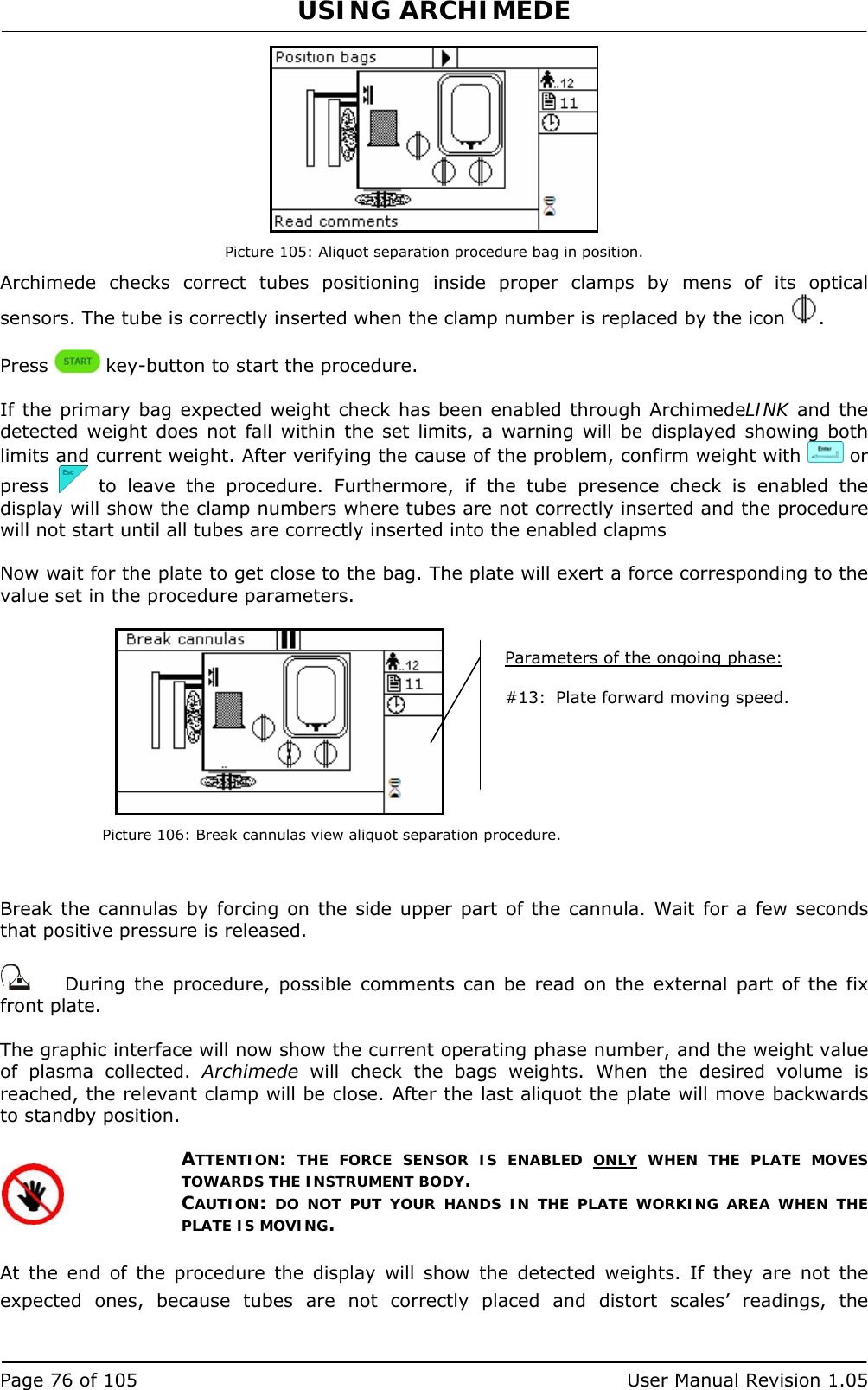
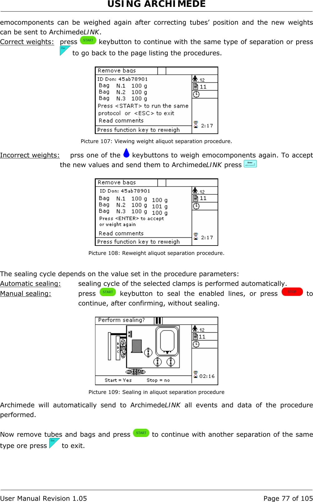
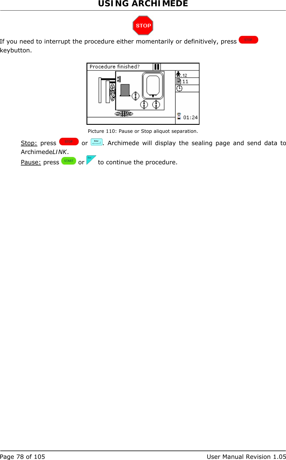
![USING ARCHIMEDE Page 74 of 105 User Manual Revision 1.05 4.6.10 PROCEDURE 11 [b] ALIQUOT SEPARATION This procedure allows to separate emocomponents in the four available bags by weighing them separately. Parameters used: 1 During the procedure, checks that tubes are properly inserted into the clamps enabled for the ongoing procedure. 2 Enables the routine controlling breaking of the primary bag cannulas. 3 Force in xx.x Kg beyond which the plate stops and waits for cannulas breaking. 4 Plate forward moving speed during cannulas breaking step. 5 Value used to calculate the force value below which the systems exits the cannulas breaking routine. V =(force measured at breaking position) – (current force). 9 Value of the maximum force applied during the procedure; the plate stops if the force exceeds this limit. 11 Selection of the sealing mode. In automatic mode, the system automatically seals the bags when the procedure is over. In manual mode, bags sealing must be confirmed. 12 Selection of clamps to be used for sealing when the procedure is over. Clamps are numbered as follows: 1 Top, 2 Plasma, 4 Buffy, 8 Bottom. The value to be set in this position is the value corresponding to the sum of the clamps used: for example, if bottom and top are to be used, the value to be set is 9. 13 Plate moving speed used in the first phase for the management of force. 14 Weight of aliquot 2. (Upper scale) 18 Value of the distance beyond which the system, after confirmation, stops the procedure if the set volumes have not been dispensed. 25 Tare of the primary bag. This value is used to calculate the product amount left in the primary bag [current weight - tare]. 29 Weight of aliquot 1. (Upper scale) 39 Weight of aliquot 3. (Lateral scale) 40 Value allowing to select the clamps to be used in the procedure. 41 Number of the profile plate to be used with the ongoing procedure. 42 Enables the air elimination routine. 43 Primary bag positioning with blade ready for weighing. 44 Scale stability check. 45 Check Correlation Distance Weight. 46 Enable scale reading. 47 IR corresponding to upper and lower bag edges.](https://usermanual.wiki/MOELCA-S-R-L/1504/User-Guide-1140271-Page-74.png)
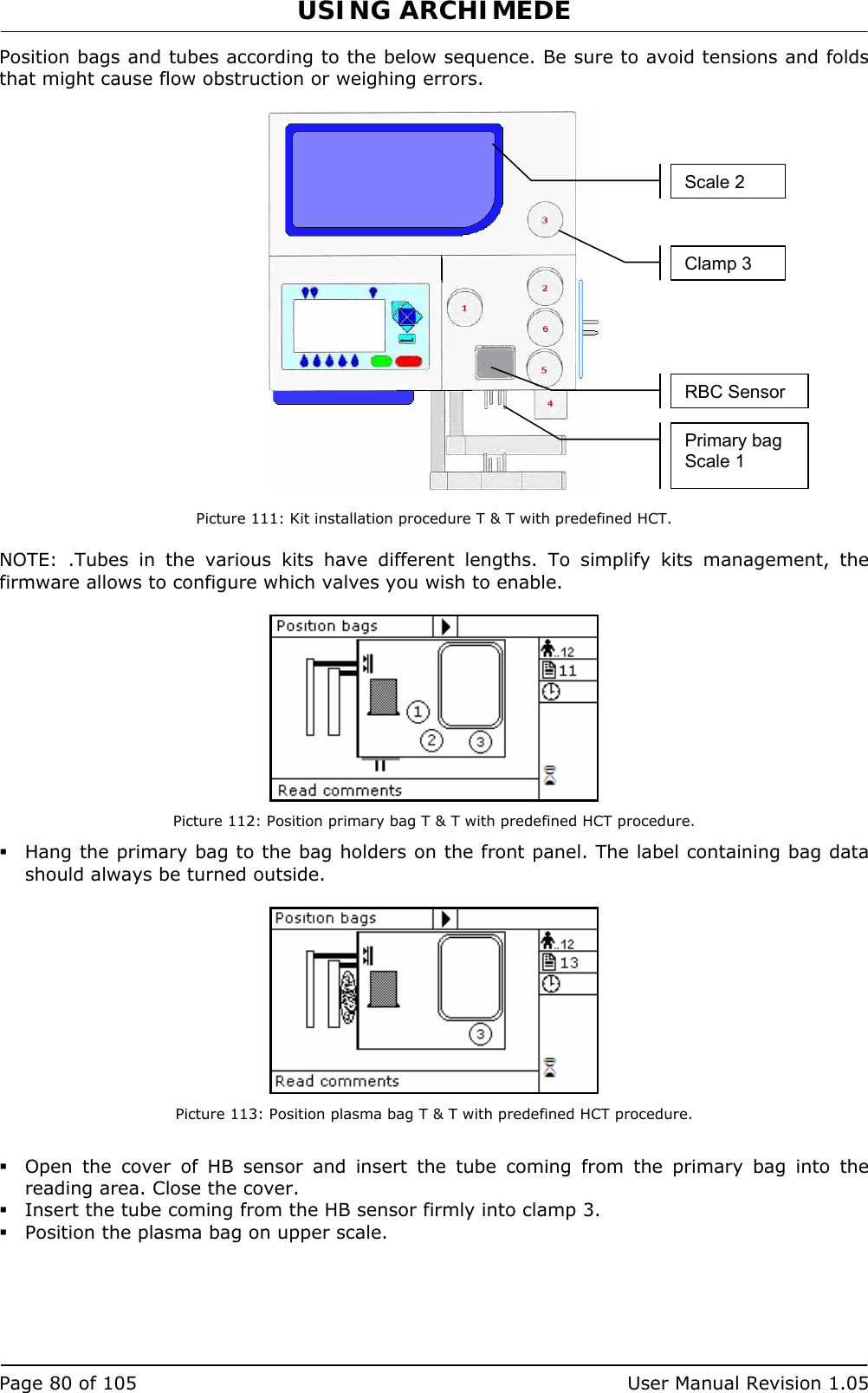
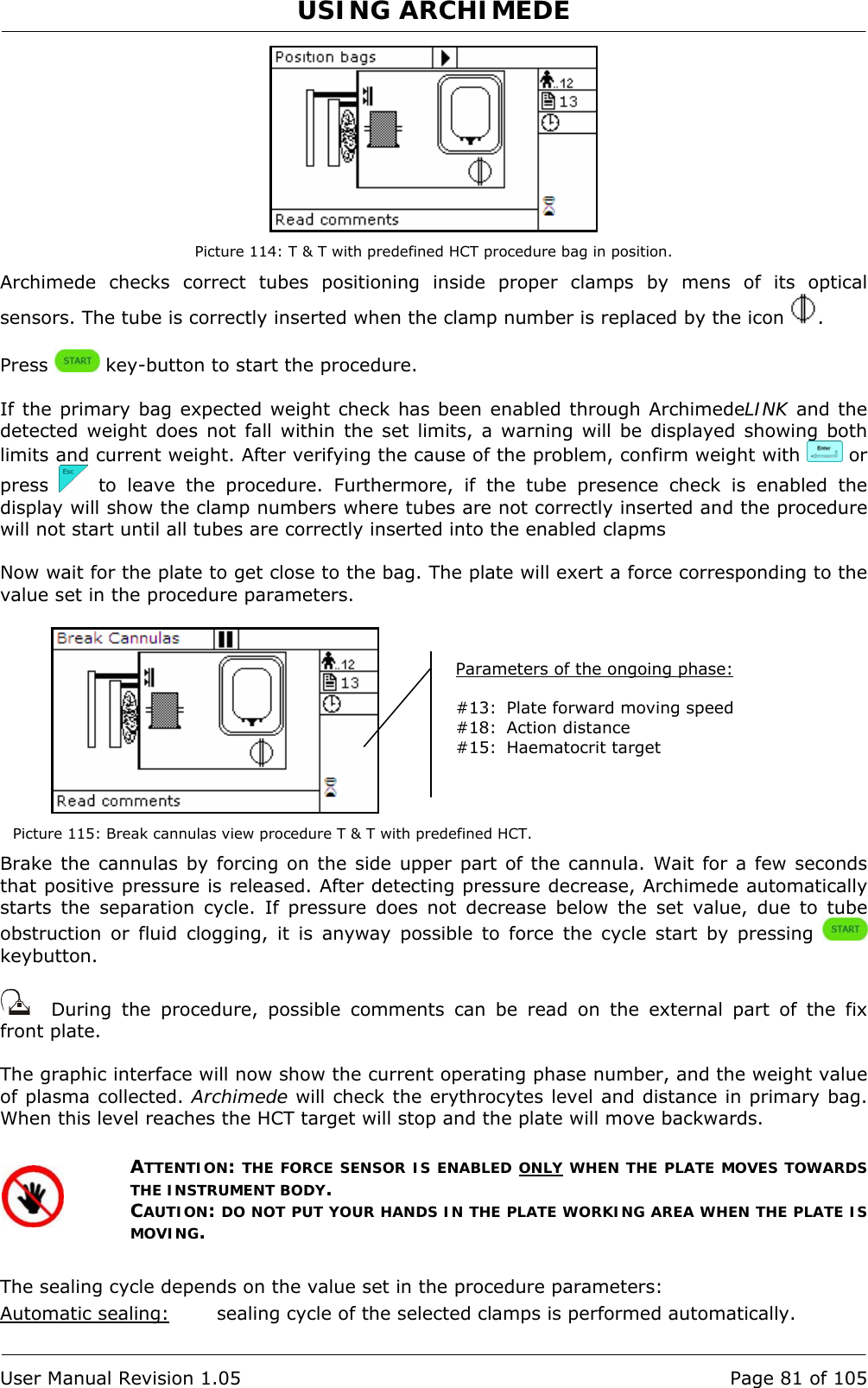
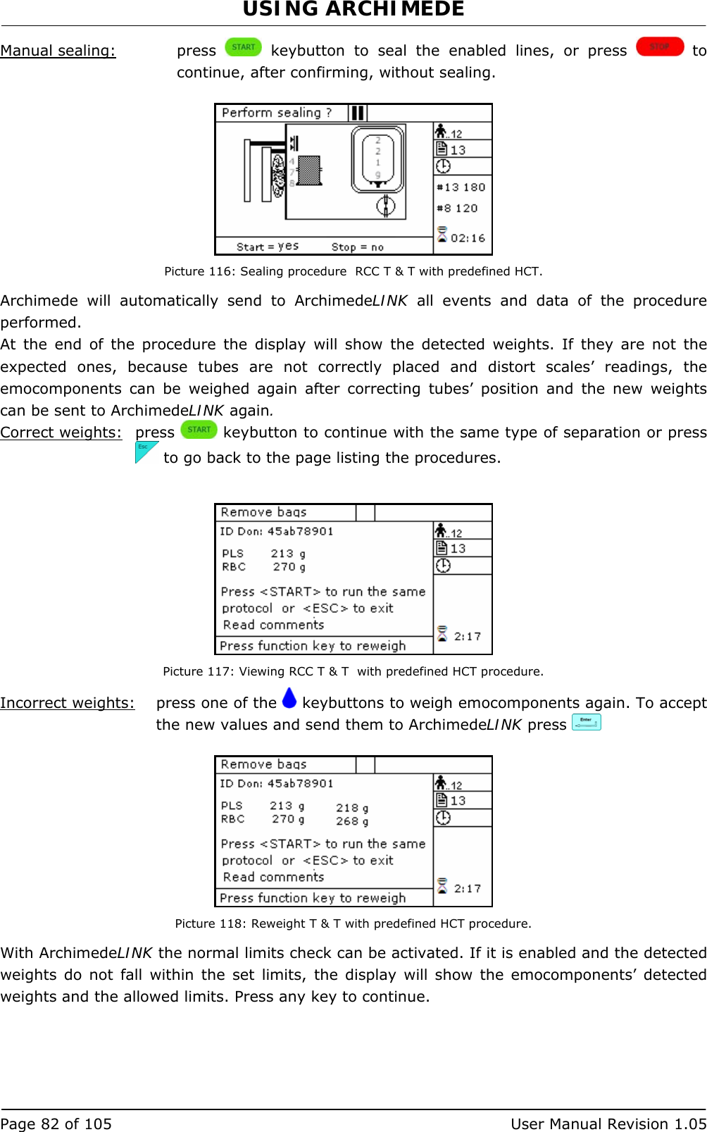
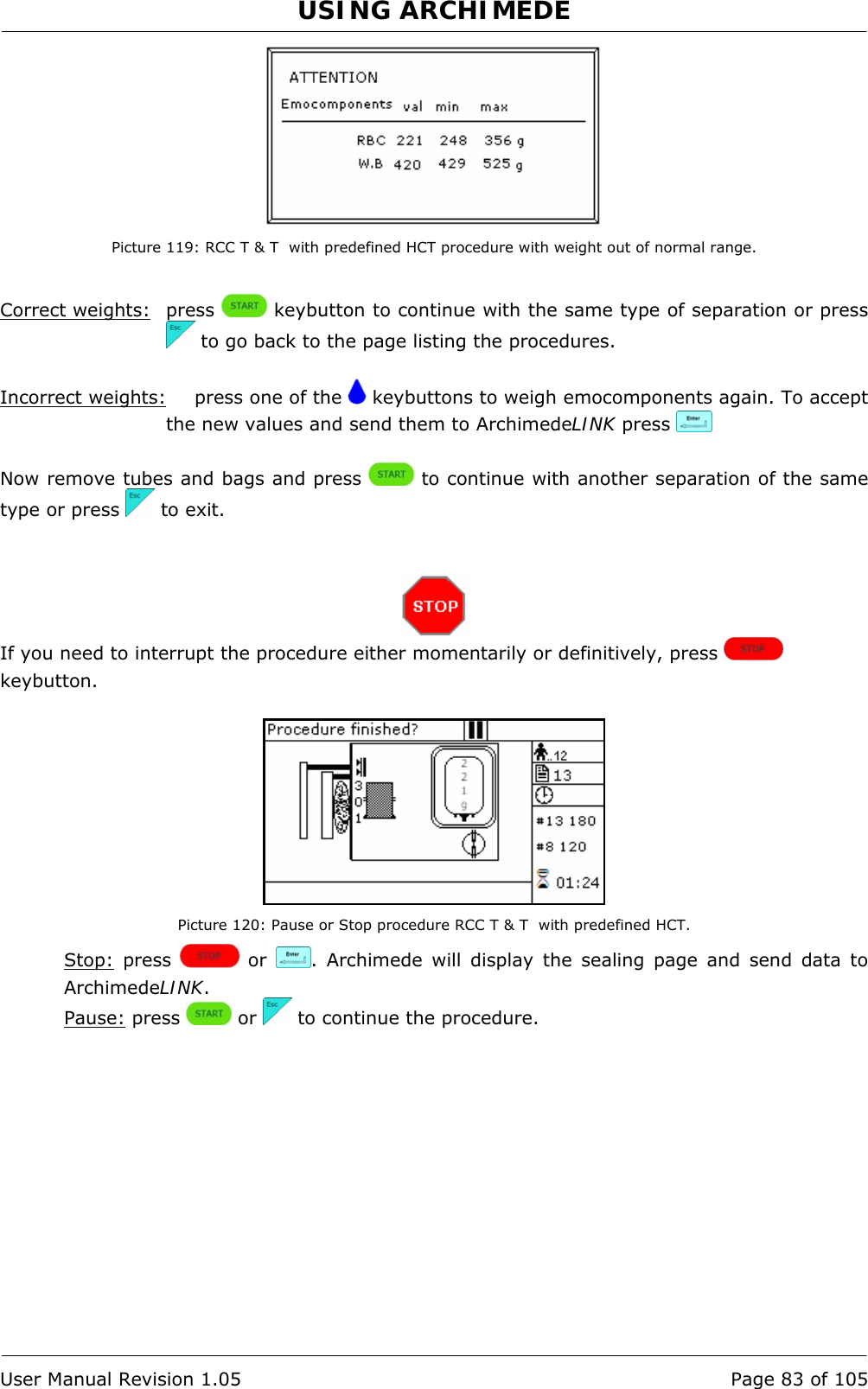
![USING ARCHIMEDE User Manual Revision 1.05 Page 79 of 105 4.6.11 PROCEDURE 13 [d] T & T for RCC diluted in Plasma + Predefined HCT. This procedure is suitable for triple bags to obtain diluted RCC in plasma with predefined haematocrit (no additive solution) and PPP. Parameters used: 1 During the procedure, checks that tubes are properly inserted into the clamps enabled for the ongoing procedure. 2 Enables the routine controlling breaking of the primary bag cannulas. 3 Force in xx.x Kg beyond which the plate stops and waits for cannulas breaking. 4 Plate forward moving speed during cannulas breaking step. 5 Value used to calculate the force value below which the systems exits the cannulas breaking routine. V =(force measured at breaking position) – (current force). 7 Value minimal of difference of reading between RBC and plasma with which it comes controlled the bag before and during the procedure 9 Value of the maximum force applied during the procedure; the plate stops if the force exceeds this limit. 11 Selection of the sealing mode. In automatic mode, the system automatically seals the bags when the procedure is over. In manual mode, bags sealing must be confirmed. 12 Selection of clamps to be used for sealing when the procedure is over. Clamps are numbered as follows: 1 Top, 2 Plasma, 4 Buffy, 8 Bottom. The value to be set in this position is the value corresponding to the sum of the clamps used: for example, if bottom and top are to be used, the value to be set is 9. 13 Plate moving speed used in the first phase for the management of force 15 Haematocrit target. 18 Value of the distance beyond which the system, after confirmation, stops the procedure if no RBCs have been detected. 25 Tare of the primary bag. This value is used to calculate the product amount left in the primary bag [current weight - tare] 40 Value allowing to select the clamps to be used in the procedure. 41 Number of the profile plate to be used with the ongoing procedure. 42 Enables the air elimination routine. 43 Primary bag positioning with blade ready for weighing. 44 Scale stability check. 45 Check Correlation Distance Weight. 46 Enable scale reading. 47 IR corresponding to upper and lower bag edges.](https://usermanual.wiki/MOELCA-S-R-L/1504/User-Guide-1140271-Page-79.png)

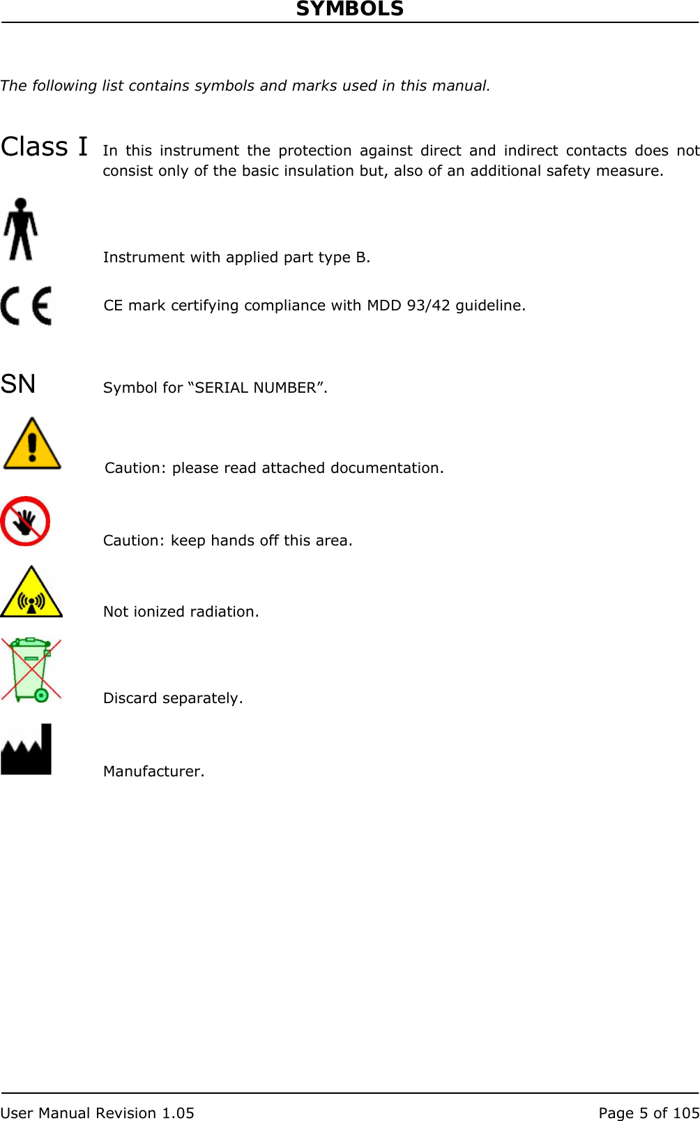
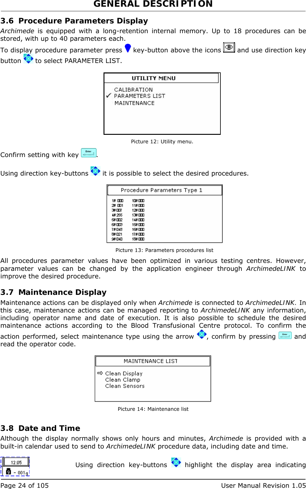
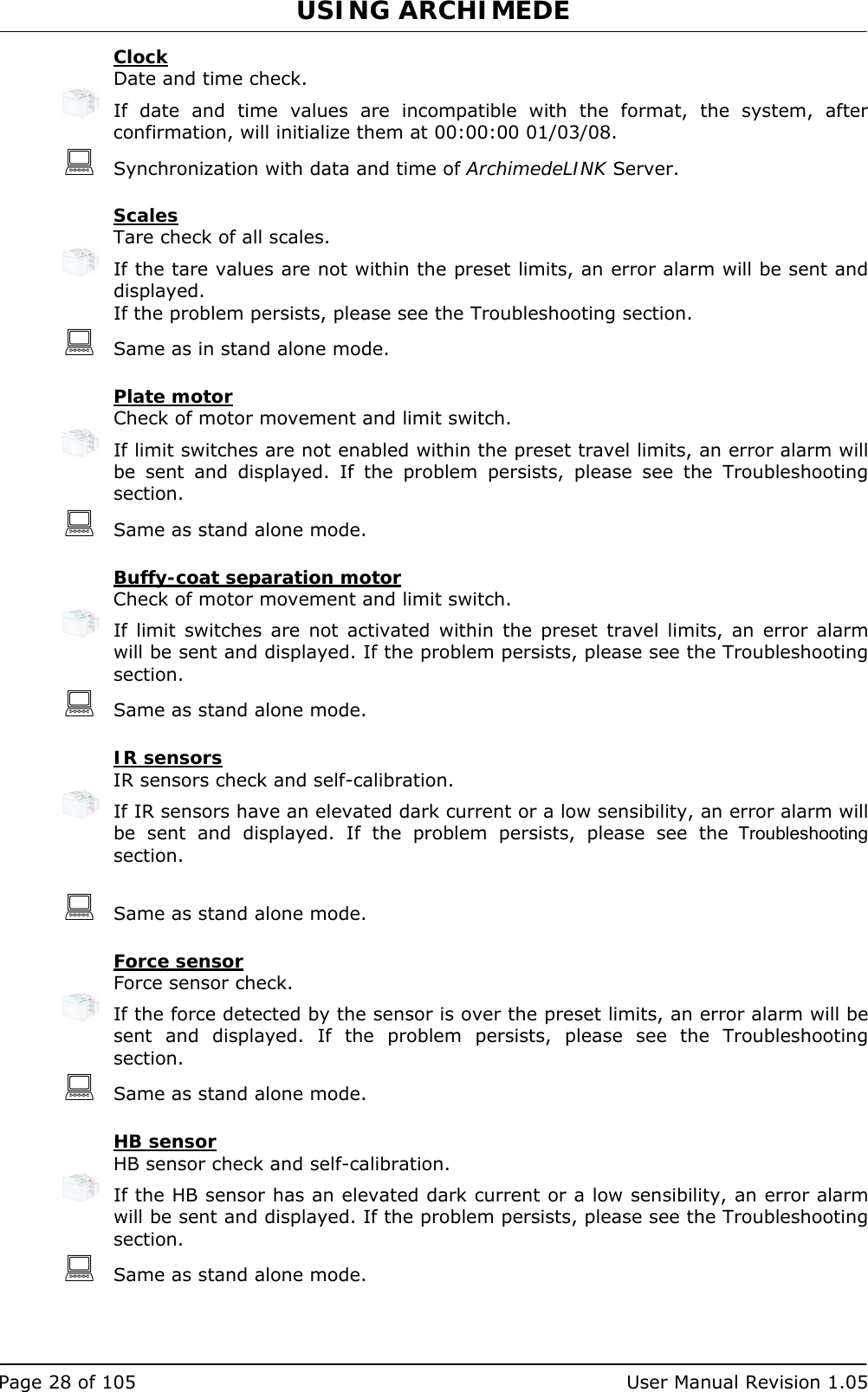
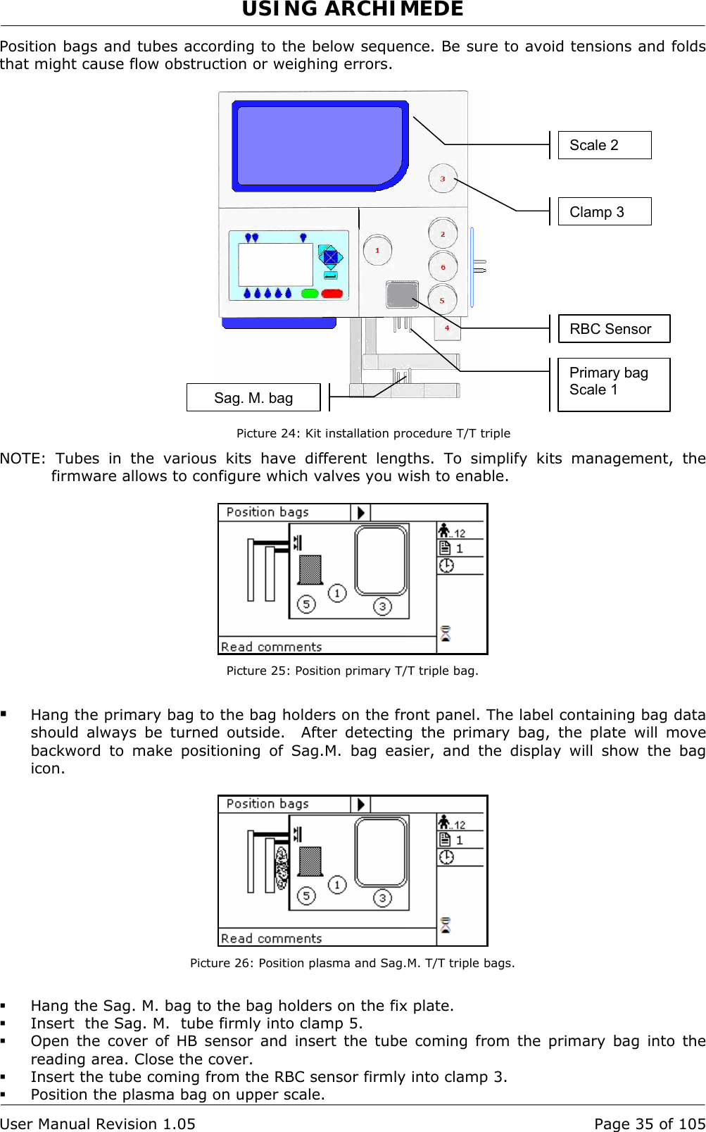
![TECHNICAL FEATURES User Manual Revision 1.05 Page 105 of 105 11 TECHNICAL FEATURES • Painted metal case. • Graphic backlight display 240 x 128. • N° 3 load cells for 2 kg: non linearity 0,02% F.S., repeatability 0,02% F.S., resolution ± 1 g. • Detection system of force exerted by the plate. • N° 4 sealing head clamps, 1 normal clamp, and one flow valve. • N° 10 optical sensor to detect buffy coat level. • Optical device to detect red blood cells presence. • Many separation procedures stored, up to a maximum of 18. • WLAN for bi-directional data transfer of procedure and configuration data. • PS2 port for external barcode-reader connection. • Adjustable sealing time from 0.5 to 4 seconds, frequency 40.68 MHz. • Environmental requirements: Temperature between 5°C and 45°C Humidity lower than 80% without condensation. • Power supply: 90 VAC 84 W 1A, 230 VAC 81 W 0.4A, fuses 2.0 AT. • Dimensions Width 435, depth 500, height 425 [mm]. • Weight: 40Kg • Transport and storage From –20°C to +70°C. Relative humidity from temperature 20% to 90% without condensation. • In accordance with: EN60601-1-2 (2001-11) IEC60601-1-2 (2001-09) EN60601-1:1990-08+ EN60601-1/Ec :1994-07 + EN60601-1/A1:1993+EN60601-1/A1/Ec:1994-07 + EN60601-1/A2:1995-06 + EN60601-1/A13:1996-01. EN60950-1(2001) + A1 EN301 489-17 V1.2.1 (2002-08). EN301 489-1 V1.6.1 (2005-09). • Electrical safety: Class I – Instrument with applied part Type B. Rule 12 MDD 93/42 – Device belonging to Class I without measurement function. Instrument not suitable for use in the presence of flammable anaesthetic mixtures with air or oxygen or nitrous oxide. Instrument for continuous working. • Instrument in compliance with MDD 93/42 EEC requirements. • International protection: IP41. • FCC ID: V991504. MOELCA s.r.l. Sede Legale Via E.Toti,101 Uffici Via del Lavoro,19. 22070 Limido Comasco (CO) 031-3520153 3520279 3524739. Fax 031-3524732 Email: info@moelca.it](https://usermanual.wiki/MOELCA-S-R-L/1504/User-Guide-1140271-Page-105.png)