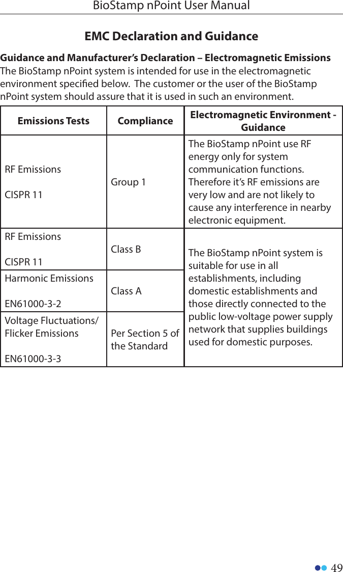
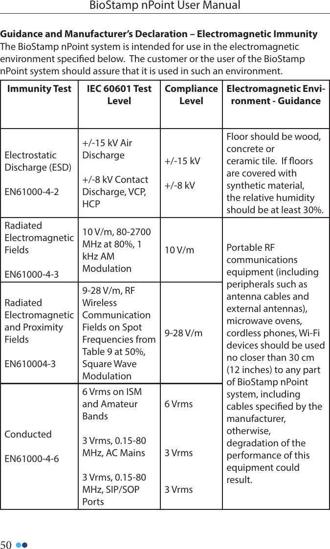
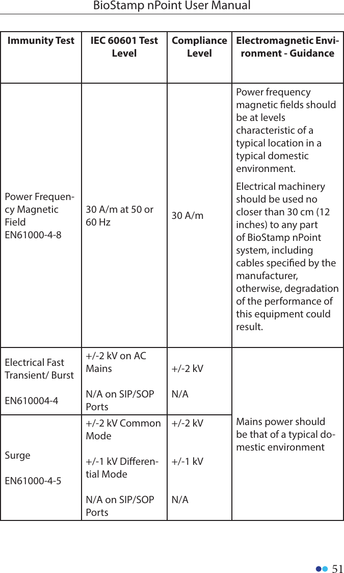
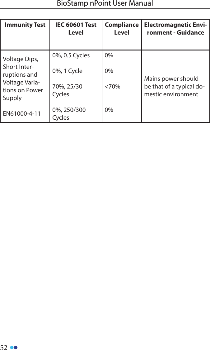
MC10 BRCS02 BRCS02 wearable sensor patch (WSP) User Manual
MC10 INC BRCS02 wearable sensor patch (WSP)
UserManual.wiki
>
MC10
>
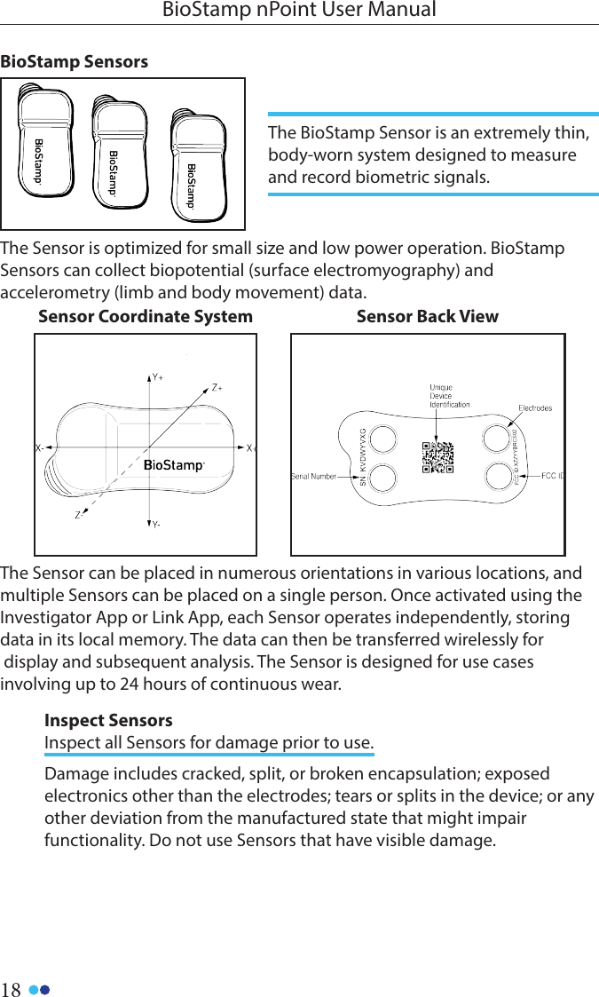
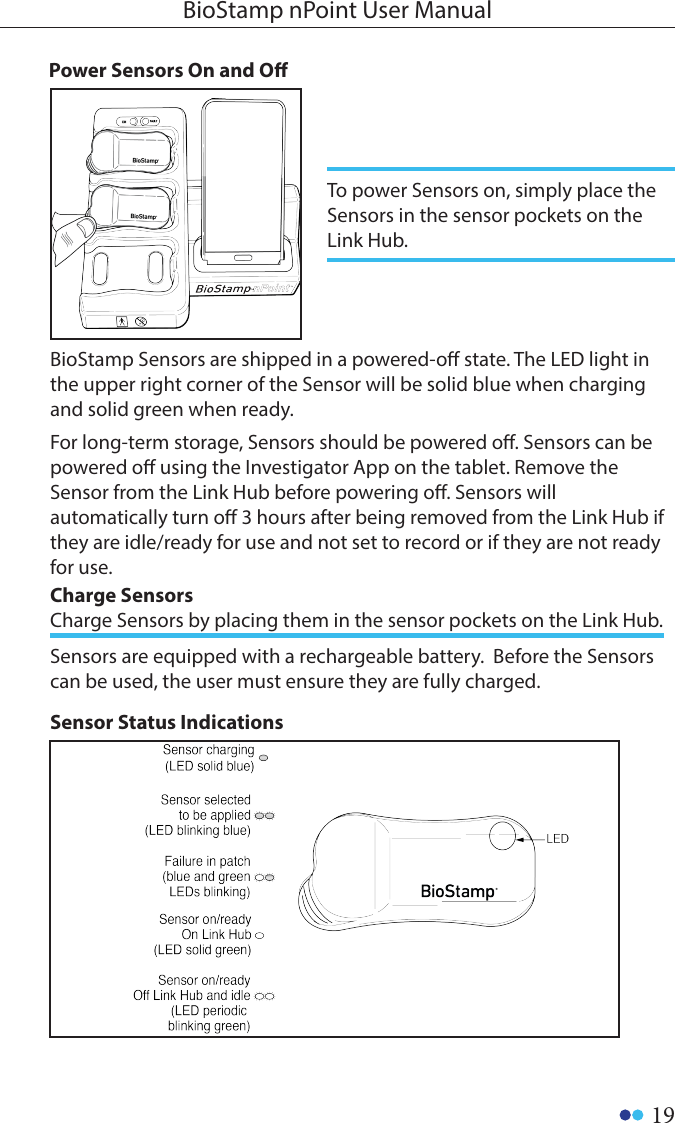
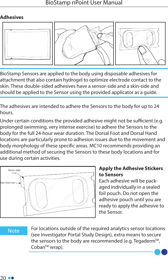
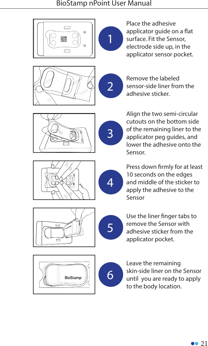
BRCS02 User Manual
User Manual
Navigation menu
Upload a User Manual
Namespaces
Wiki Guide
HTML
PDF
Info
Views
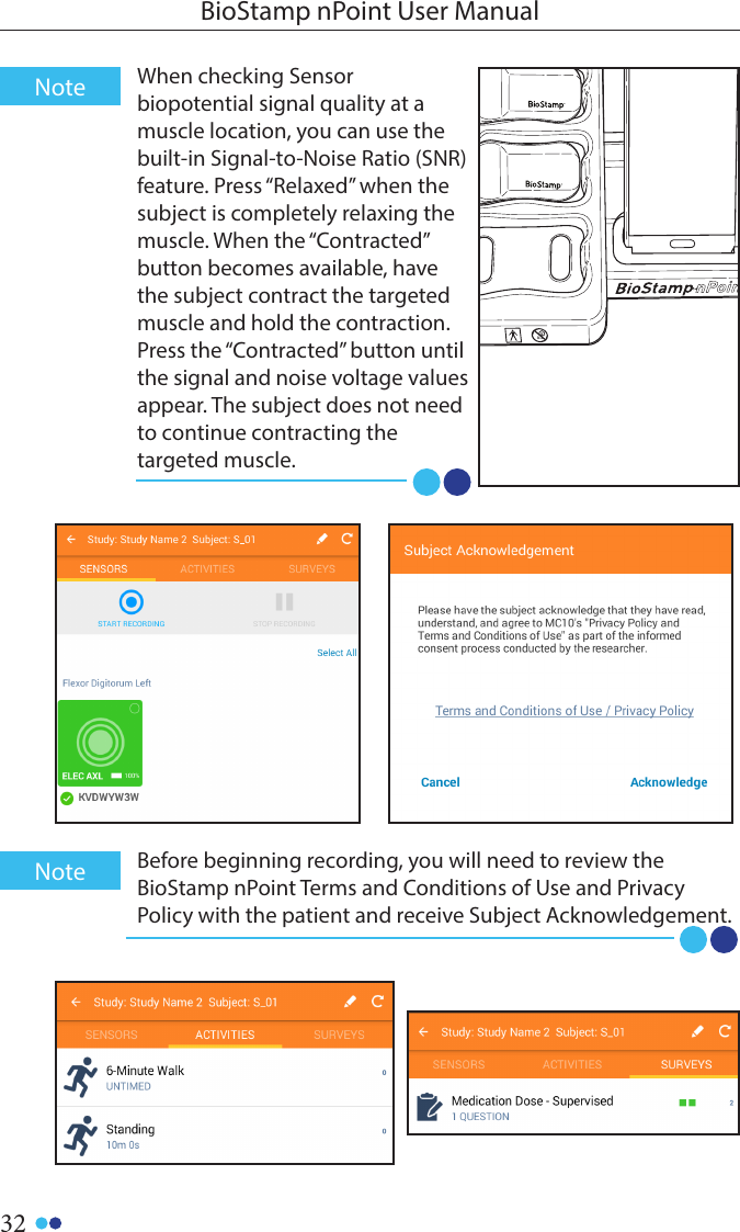
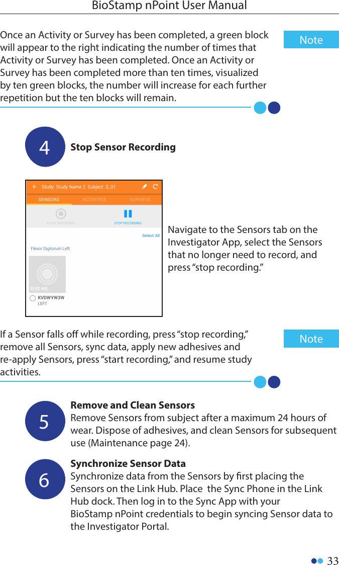
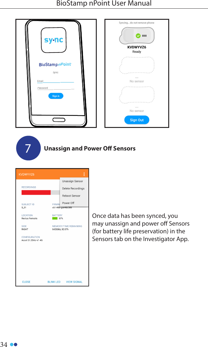
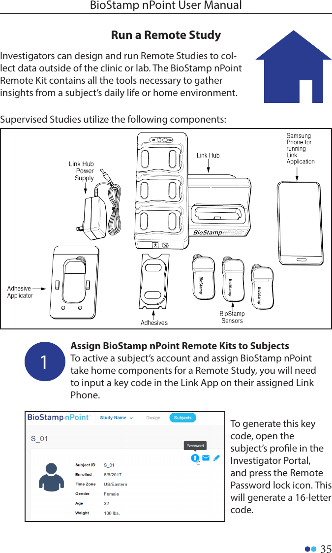
User Manual
Discussion / Help
Navigation