M Labs Technologies LN01A GPS Tracker User Manual
M-Labs Technologies, LLC GPS Tracker User Manual
UserManual.wiki
>
M Labs Technologies
>
LN01A User Manual
User_Manual
Navigation menu
Upload a User Manual
Namespaces
Wiki Guide
HTML
PDF
Info
Views
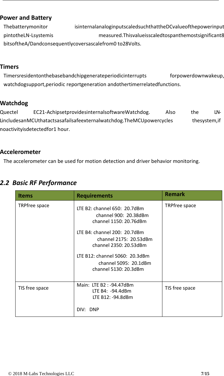
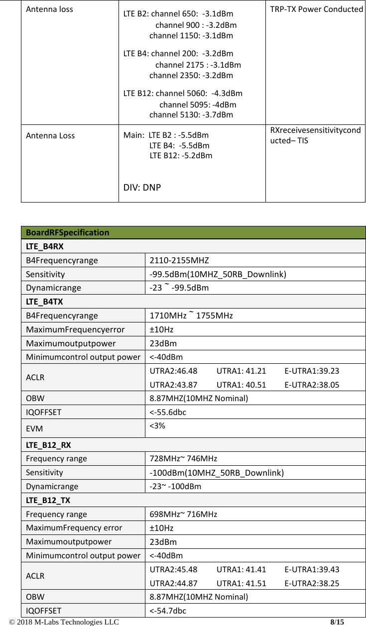
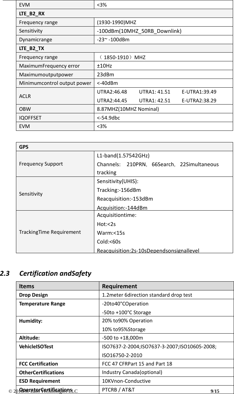
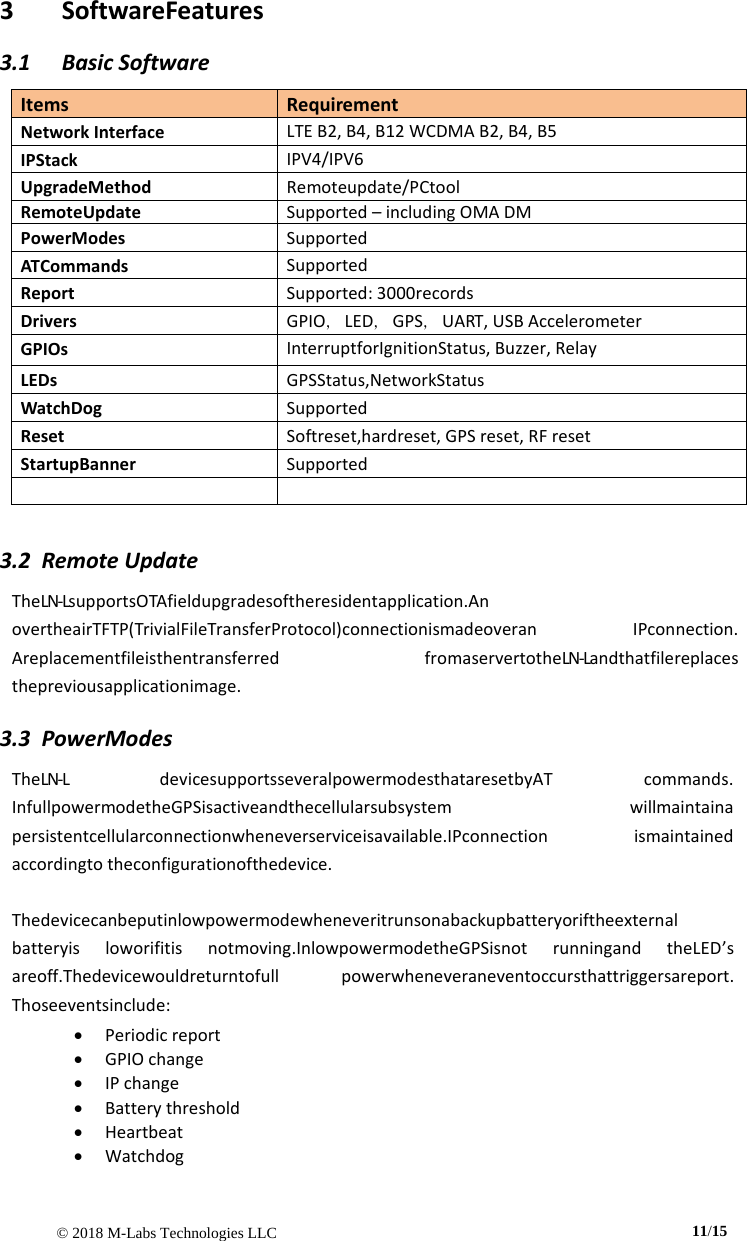
User Manual
Discussion / Help
Navigation
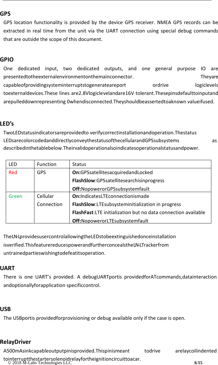
![© 2018 M-Labs Technologies LLC 15/15 MechanicalStructure (mm) 批注 [GE1]: Needs update](https://usermanual.wiki/M-Labs-Technologies/LN01A/User-Guide-3933822-Page-14.png)