Linx Technologies OTX-XXX-LRHSA Long-Range Handheld Transmitter User Manual OTX xxx HH LR8 HS Data Guide 3 30 07

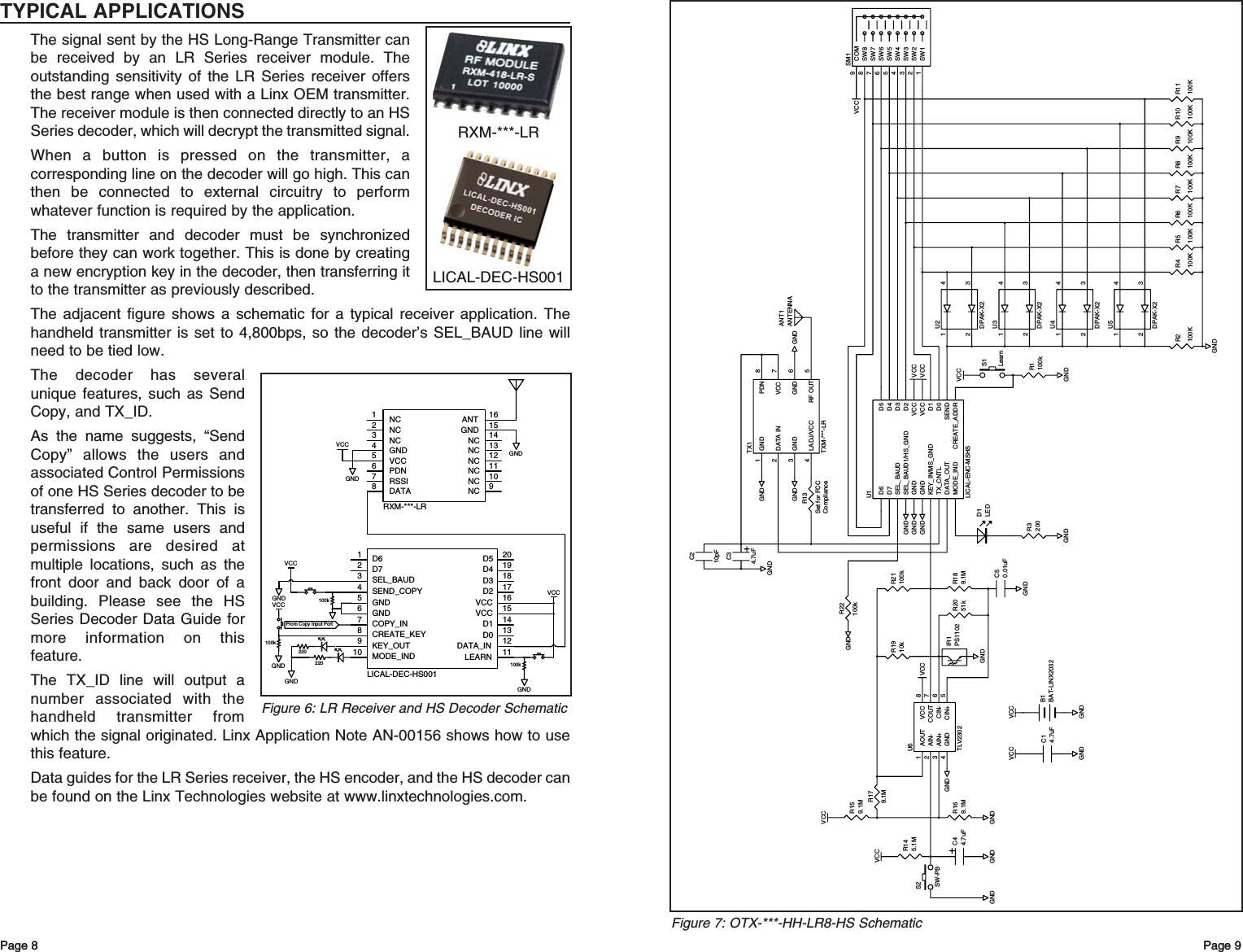
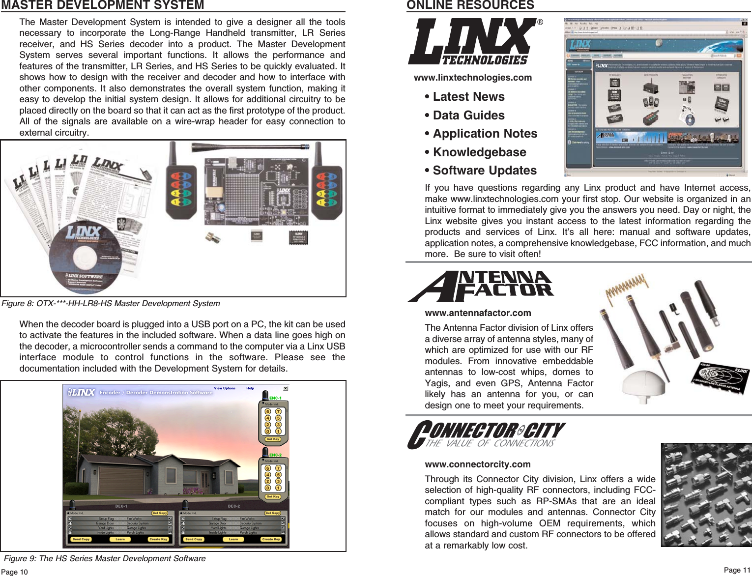
Linx Technologies Long-Range Handheld Transmitter OTX xxx HH LR8 HS Data Guide 3 30 07

Users Manual

DESCRIPTIONThe Linx OTX-***-HH-LR8-HS Long-RangeHandheld Transmitter is ideal for general-purpose remote control and commandapplications which require high security andlong transmission distances. This unit has beenpre-certified for FCC Part 15, Industry Canada,and European CE (433MHz only) compliance,reducing costs and time to market. Available in315, 418 (standard), or 433.92MHz, this smallremote has a transmission range of up to 1,000feet when combined with an LR Series receiver.The transmitter unit can be configured with 1 to8 buttons and the keypad and labeling can bemodified to meet specific OEM customerrequirements. Security is dramaticallyenhanced by the on-board HS Series encoder,which uses Cipherlinx™ technology, a high-security encryption algorithm and wirelessprotocol. When paired with an HS Seriesdecoder, transmitter identity can be determinedand button permissions established. The unituses a single 3V CR2032 lithium button cell.FEATURESFCC, Canada, and CE pre-certifiedHighly secure, encrypted transmission1 to 8 buttonsCustomizable keypadAPPLICATIONS INCLUDESecure Remote Control Keyless EntryGarage / Gate OpenersLighting ControlCall SystemsHome / Industrial AutomationWire EliminationOEM ConfigurationsWith a one-time NRE andminimum order, Linx can configurethe keypad and label areas tomeet your specific requirements.Contact Linx for details.HS LONG-RANGE HANDHELD TRANSMITTER DATA GUIDE0.60"0.20"1.375"2.81"1.62"2.00"1.35"R 0.2"Revised 3/30/07Figure 1: Package DimensionsWIRELESS MADE SIMPLE®2134ABCDONONONONFASCOLightsSpaONONONOFFOFFOFFPoolPART # DESCRIPTIONOTX-***-HH-LR8-HS-xxx  HS Long-Range TransmitterMDEV-***-HH-LR8-HS HH-LR8 Master Development System*** = 315, 418 (Standard), 433.92MHzxxx = Reserved for custom colors.  Leave blank for standard blackORDERING INFORMATIONCipherLinxTechnologyTM
Page 3Page 2THEORY OF OPERATIONThe OTX-***-HH-LR8-HS Long-Range Handheld Transmitter combines an LRSeries transmitter and an antenna with an on-board HS Series encoder to forma highly reliable and secure RF remote-control transmitter. The LR Seriestransmitter is a low-cost, high-performance synthesized OOK transmitter. It’ssynthesized architecture delivers outstanding stability and frequency accuracy,while minimizing the effects of antenna port loading and mismatching. Thisreduces or eliminates frequency pulling, bit contraction, and other negativeeffects that are common to SAW-based transmitter architectures, providing asignificantly higher level of performance and reliability.When a button is pressed on the transmitter, power is applied to the internalcircuitry and the encoder is enabled. The encoder then detects the logic statesof the button data lines. These states are formatted into an encrypted messagethat is output to the transmitter module. This cycle continues until the button isreleased. The encoder data is used to modulate the transmitter, which conveysthe data into free space through the antenna. Once data is received, a decoderIC is used to decrypt the transmitter’s commands. If decryption is successful, thedecoder’s outputs are set to replicate the transmitter’s button states. Theseoutputs can then be used to activate whatever external circuitry is required by theapplication.The transmitter is compatible with several Linx receiver products. Forapplications where range is critical, the LR Series receiver is the best choice dueto its outstanding sensitivity. When the transmitter is combined with an LR Seriesreceiver and an HS Series decoder, ranges of up to 1,000 feet are possible.Applications operating over shorter distances will also benefit from the increasedlink reliability and superior noise immunity provided by the LR Series receiver.1. Characterized, but not testedNotesELECTRICAL SPECIFICATIONSParameter Designation Min. Typical Max. Units NotesPOWER SUPPLYOperating Voltage VCC 2.1 3.0 3.6 VDC –Supply Current ICC – 3.4 – mA –Power-Down Current IPDN – 5.0 – nA 1TRANSMITTER SECTIONTransmit Frequency Range: FCOTX-315-HH-LR8-HS – 315 – MHz –OTX-418-HH-LR8-HS – 418 – MHz –OTX-433-HH-LR8-HS – 433.92 – MHz –Center Frequency Accuracy – -50 – +50 kHz –ENVIRONMENTALOperating Temperature Range – -40 – +85 °C 1SECURITY OVERVIEWThe HS Long-Range Handheld transmitter uses the HS Series encoder, which isbased on Cipherlinx™ technology. CipherLinx™ is a high-security encryptionalgorithm and wireless protocol designed for remote control and remote keylessentry applications. It provides a much greater level of security and many morefeatures than older technologies on the market, such as fixed address or “rollingcode” systems. Additionally, the CipherLinx™ protocol is much more advancedthan the simple PWM method employed by many systems. By utilizing anadvanced serial protocol, CipherLinx™ is able to offer superior noise immunity,greater range, and greater link reliability, all of which are key factors in a wirelesssystem. CipherLinx™ never sends or accepts the same data twice, never loses sync, andchanges codes with every packet, not just every button press. The encryptionthat is used in CipherLinx™ is based on the Skipjack cipher developed by theU.S. National Security Agency (NSA), and is widely considered one of the mostsecure ciphers available. The CipherLinx™ algorithm has been evaluated byIndependent Security Evaluators (ISE), a company that has testified beforeCongress as experts on electronic security. They concluded that “In short, theCipherLinx™ protocol in the HS Series is well-designed and is an excellentchoice for applications requiring a secure unidirectional link.” In addition to this high level of security, CipherLinx™ also offers a number offeatures that are unique among remote control products. These include a largenumber of data lines, internal key generation, “button level” control permissions,an optional encoder PIN, as well as the ability for the decoder to identify theoriginating encoder.CipherLinx™ is based on the NSA-designed cipher Skipjack. Skipjack is a blockcipher that has 80-bit keys and 64-bit data blocks. Since each packet is longerthat 64 bits, Skipjack must be employed in an encryption mode. The particularencryption mode chosen for CipherLinx™ is based on the CMC encryptionmode, so that the resulting cipher is a special kind of function known as a “strongPRP” (sPRP). The encryption mode uses several invocations of Skipjack toencrypt the 128 bits in each message. The definition of these terms is quiteinvolved, but more details can be found in ISE’s evaluation report atwww.cipherlinx.com. The HS Series uses a 40-bit counter to change the appearance of eachmessage. This large counter value and the timing associated with the protocolensure that the same message is never sent twice and prevents the encoderfrom ever losing sync with the decoder.The user generates the key with the decoder through multiple button presses.This is ensures that the key is random and chosen from among all 280 possiblekeys. Since all of the keys are created by the user and are internal to the part,there is no list of numbers anywhere that could be accessed to compromise thesystem.The user or manufacturer may also set “button level” Control Permissions.Control Permissions determine how the decoder will respond to the reception ofa valid command, either allowing the activation of an individual data line or not.The decoder is programmed with the permission settings during set-up, andthose permissions are retained in the decoder’s non-volatile memory.
Page 5Page 4USING THE OPTIONAL KEYPAD PINFor higher security applications, the HS Series encoder has the option to set aPersonal Identification Number (PIN) to control access to the encoder.  This PINis a four-button combination of the eight buttons which must be entered beforethe transmitter will send any commands. It will need to be re-entered after fifteenminutes of inactivity. If no PIN is created, then the transmitter will activate assoon as a button is pressed.Creation of a keypad PIN1. Use a paper clip to press the CREATE_KEY button on the back of thetransmitter. The MODE_IND LED will begin flashing until either a PIN issuccessfully entered or fifteen seconds has passed.2. To enter the PIN, press a sequence of any four buttons. The MODE_IND willstop flashing and the PIN will be created.3. To cancel Create PIN Mode prior to the fourth entry, either wait for the fifteensecond timeout to pass or press the CREATE_KEY button. The MODE_INDLED will stop flashing and no PIN will be created. 4. If a new KEY is created, the PIN will be automatically erased. Using the PIN1. The PIN is entered by pressing each button until all four entries have beenmade. There is a maximum two-second time limit between entries, after whichthe PIN must be re-entered in its entirety.2. Once the PIN is successfully entered, the transmitter will be operational unlessit is inactive for fifteen minutes, in which case the PIN must be re-entered.CONTENTION CONSIDERATIONSIt is important to understand that only one transmitter at a time can be activatedwithin a reception area. While the transmitted signal consists of encoded digitaldata, only one carrier of any particular frequency can occupy airspace withoutcontention at any given time.  If two transmitters are activated in the same areaat the same time, then the signals will interfere with each other and the decoderwill not see a valid transmission, so it will not take any action.BATTERY REPLACEMENTThe transmitter uses a standard CR2032 lithiumbutton cell. In normal use, it will provide 1 to 2 yearsof operation. To replace the battery, remove theaccess cover by pressing firmly on the label area andsliding it off. Once the unit is open, remove thebattery by sliding it from beneath the holder. Theremay be the risk of explosion if the battery is replacedby the wrong type. Replace it with the same type ofbattery while observing the polarity shown in theadjacent figure.TYPICAL SYSTEM SETUPThe HS Series Long-Range Handheld Transmitter is intended to make usersetup straightforward while ensuring the highest possible security. This inherentease of use can be illustrated by a typical user setup. The Typical Applicationssection of the HS Series Decoder Data Guide shows the circuit schematics onwhich the receiver examples are based.1. Create and exchange a key from a decoder to the handheld transmitterThe handheld transmitter includes an on-board infrared receiver designed tooptically receive the decoder’s keytransmission. Sending the key in thismanner preserves security while avoidingthe need for a hardwire connection. The high security key is created andexchanged by placing the decoder in theCreate Key Mode. The decoder’sMODE_IND LED will light to indicate thatthe decoder has entered Create KeyMode. The decoder’s CREATE_KEYbutton is then pressed ten times to createthe key. After the tenth press, the MODE_IND LED will turn off and the decoderwill output the key via a 900nm infrared diode on the KEY_OUT line. A paper clipis used to press the GET_KEY button on the back of the transmitter. Hold theback of the transmitter near the decoder’s infrared diode within twenty seconds.Once the key has been transferred, the MODE_IND LEDs on the transmitter anddecoder illuminate to indicate success.2. Establish Control PermissionsNext, the user defines which buttons on the transmitter will be acknowledged bythe decoder. The HS Series Control Permissions allow each transmitter in asystem to activate different data lines. This is especially useful in applicationswhere differing user access or activation capabilities are desired. Consider this practical example: a three-door garage houses Dad’s Corvette,Mom’s Mercedes, and Son’s Yugo. With most competitive products, any user’skeyfob could open any garage door as long as the addresses match. In an HS-based system, the keyfobs could easily be configured to open only certain doors(guess which one Son gets to open!). Setting the control permissions is intuitive. The user presses the decoder’sLEARN button. The decoder’s MODE_IND LED will start flashing and the usersimply presses the handheld transmitter buttons that will be recognized. ControlPermissions are stored when the LEARN button is pressed again orautomatically after seventeen seconds. There are other powerful options, such as programming a user PIN or copying adecoder, but these two steps are all that is required for a typical setup.GET_KEY ButtonCREATE_PINButtonMODE_INDWindowFigure 2: Button Access HolesFigure 3: Battery AccessBattery Access+
OTX-***-HH-LR8-HS BUTTON ASSIGNMENTSThis diagram illustrates the relationship between the button locations andencoder data lines.ASSEMBLY DIAGRAMPage 7Page 6 Page 7INSTRUCTION TO THE USERThis device complies with Part 15 of the FCC Rules.Operation of this device is subject to the following two conditions:(1) This device may not cause harmful interference, and(2) this device must accept any interference received, including interferencethat may cause undesired operation.This equipment has been tested and found to comply with the limits for a ClassB digital device, pursuant to Part 15 of the FCC Rules. These limits aredesigned to provide reasonable protection against harmful interference in aresidential installation. This equipment generates, uses and can radiate radiofrequency energy and, if not installed and used in accordance with theinstructions, may cause harmful interference to radio communications.However, there is no guarantee that interference will not occur in a particularinstallation. If this equipment does cause harmful interference to radio ortelevision reception, which can be determined by turning the equipment off andon, the user is encouraged to try to correct the interference by one or more ofthe following measures: Reorient or relocate the receiving antenna. Increase the separation between the equipment and receiver. Connect the equipment into an outlet on a circuit different from that to which thereceiver is connected. Consult the dealer or an experienced radio/TV technician for help. This equipment has been certified to comply with the limits for a Class Bcomputing device, pursuant to FCC Rules. In order to maintain compliance withFCC regulations, shielded cables must be used with this equipment. Operationwith non-approved equipment or unshielded cables is likely to result ininterference to radio and TV reception. The user is cautioned that changes andmodifications made to the equipment without the approval of manufacturercould void the user’s authority to operate this equipment. Place the above statement in the instruction manual or insert card.COMPLIANCE REQUIREMENTSThe OTX-***-HH-LR8-HS has been pre-certified by Linx Technologies for FCCPart 15 and Industry Canada RSP-100 compliance. The 433.92MHz version hasalso been tested for CE compliance for use in the European Union. The 315MHzand 418MHz versions are not legal for use in Europe.LABELING / INSTRUCTION REQUIREMENTSThe OTX-***-HH-LR8-HS Long-Range Handheld Transmitter has already beenlabeled in accordance with FCC, Industry Canada, and CE regulations in effectas of the date of this document. No further labeling of the unit is needed;however, it is necessary to include the following statement in the end product’sinstruction manual or insert card for FCC compliance. Industry Canada onlyrequires the shaded portion. The EU does not require a statement.Page 6FCC ID: OJM-OTX-XXX-LRMSA FCC ID: OJM-OTX-XXX-LRMSA IC: 5840A-LRMSXXXA IC: 5840A-LRMSXXXA 418MHz 418MHz Figure 5: OTX-***-HH-LR8-HS AssemblyD6 D7D4 D5D2 D3D0 D1Figure 4: OTX-***-HH-LR8-HS Button Assignments
Page 9Page 8 Page 9VCCR1100kSW11SW22SW33SW44SW55SW66SW77SW88COM9SM1R2100KVCC1234U3DPAK-X2VCCGNDGND1234U5DPAK-X21234U4DPAK-X2VCCVCCGNDGNDGNDS1LearnGNDD1LEDR3200GNDR4100KGNDR5100KR6100KR7100KR8100KR9100KR10100KR11100KVCCGNDB1BAT-LINX2032ANT1ANTENNA1234U2DPAK-X2GND1DATA IN2GND3LADJ/VCC4RF OUT 5GND 6VCC 7PDN 8TX1TXM-***-LRGNDGNDGNDR13C14.7uFD6D7SEL_BAUDSEL_BAUD1/HS_GNDGNDGNDKEY_IN/MS_GNDTX_CNTLDATA_OUTMODE_IND CREATE_ADDRSENDD0D1VCCVCCD2D3D4D5U1LICAL-ENC-MSHSC34.7uFC210pFGNDGNDAOUT1AIN-2AIN+3GND4CIN+ 5CIN- 6COUT 7VCC 8U6TLV2302R21100kVCCR189.1MR2051kC50.01uFVCCVCCGNDGNDGNDGNDC44.7uFR169.1MR159.1MR1910kR145.1MR179.1MIR1PS1102S2SW-PBGNDR22100kSet for FCCComplianceFigure 7: OTX-***-HH-LR8-HS SchematicPage 8TYPICAL APPLICATIONSThe signal sent by the HS Long-Range Transmitter canbe received by an LR Series receiver module. Theoutstanding sensitivity of the LR Series receiver offersthe best range when used with a Linx OEM transmitter.The receiver module is then connected directly to an HSSeries decoder, which will decrypt the transmitted signal.When a button is pressed on the transmitter, acorresponding line on the decoder will go high. This canthen be connected to external circuitry to performwhatever function is required by the application.The transmitter and decoder must be synchronizedbefore they can work together. This is done by creatinga new encryption key in the decoder, then transferring itto the transmitter as previously described. The adjacent figure shows a schematic for a typical receiver application. Thehandheld transmitter is set to 4,800bps, so the decoder’s SEL_BAUD line willneed to be tied low. The decoder has severalunique features, such as SendCopy, and TX_ID.As the name suggests, “SendCopy” allows the users andassociated Control Permissionsof one HS Series decoder to betransferred to another. This isuseful if the same users andpermissions are desired atmultiple locations, such as thefront door and back door of abuilding. Please see the HSSeries Decoder Data Guide formore information on thisfeature.The TX_ID line will output anumber associated with thehandheld transmitter fromwhich the signal originated. Linx Application Note AN-00156 shows how to usethis feature.Data guides for the LR Series receiver, the HS encoder, and the HS decoder canbe found on the Linx Technologies website at www.linxtechnologies.com.GNDGNDVCCNC1NC2NC3GND4VCC5PDN6RSSI7DATA8NC 9NC 10NC 11NC 12NC 13NC 14GND 15ANT 16RXM-***-LR220 100kD6D7SEL_BAUDSEND_COPYGNDGNDCOPY_INCREATE_KEYKEY_OUTMODE_INDD5D4D3D2VCCVCCD1D0DATA_INLEARN12345678910 11121314151617181920LICAL-DEC-HS001From Copy Input Port100k100kGNDGNDGNDVCCVCCVCCGND220Figure 6: LR Receiver and HS Decoder SchematicRXM-***-LRLICAL-DEC-HS001
MASTER DEVELOPMENT SYSTEMThe Master Development System is intended to give a designer all the toolsnecessary to incorporate the Long-Range Handheld transmitter, LR Seriesreceiver, and HS Series decoder into a product. The Master DevelopmentSystem serves several important functions. It allows the performance andfeatures of the transmitter, LR Series, and HS Series to be quickly evaluated. Itshows how to design with the receiver and decoder and how to interface withother components. It also demonstrates the overall system function, making iteasy to develop the initial system design. It allows for additional circuitry to beplaced directly on the board so that it can act as the first prototype of the product.All of the signals are available on a wire-wrap header for easy connection toexternal circuitry.When the decoder board is plugged into a USB port on a PC, the kit can be usedto activate the features in the included software. When a data line goes high onthe decoder, a microcontroller sends a command to the computer via a Linx USBinterface module to control functions in the software. Please see thedocumentation included with the Development System for details.Page 11Page 10ONLINE RESOURCES• Latest News• Data Guides• Application Notes• Knowledgebase• Software UpdatesIf you have questions regarding any Linx product and have Internet access,make www.linxtechnologies.com your first stop. Our website is organized in anintuitive format to immediately give you the answers you need. Day or night, theLinx website gives you instant access to the latest information regarding theproducts and services of Linx. It’s all here: manual and software updates,application notes, a comprehensive knowledgebase, FCC information, and muchmore.  Be sure to visit often!www.antennafactor.comThe Antenna Factor division of Linx offersa diverse array of antenna styles, many ofwhich are optimized for use with our RFmodules. From innovative embeddableantennas to low-cost whips, domes toYagis, and even GPS, Antenna Factorlikely has an antenna for you, or candesign one to meet your requirements. www.connectorcity.comThrough its Connector City division, Linx offers a wideselection of high-quality RF connectors, including FCC-compliant types such as RP-SMAs that are an idealmatch for our modules and antennas. Connector Cityfocuses on high-volume OEM requirements, whichallows standard and custom RF connectors to be offeredat a remarkably low cost. ®www.linxtechnologies.comFigure 8: OTX-***-HH-LR8-HS Master Development SystemFigure 9: The HS Series Master Development Software
LINX TECHNOLOGIES, INC.159 ORT LANEMERLIN, OR 97532PHONE: (541) 471-6256FAX: (541) 471-6251www.linxtechnologies.comU.S. CORPORATE HEADQUARTERSWIRELESS MADE SIMPLE®Linx Technologies is continually striving to improve the quality and function of its products. Forthis reason, we reserve the right to make changes without notice. The information contained inthis Data Guide is believed to be accurate as of the time of publication. Specifications are basedon representative lot samples. Values may vary from lot to lot and are not guaranteed. LinxTechnologies makes no guarantee, warranty, or representation regarding the suitability orlegality of any product for use in a specific application. None of these devices is intended for usein applications of a critical nature where the safety of life or property is at risk. The user assumesfull liability for the use of product in such applications. Under no conditions will Linx Technologiesbe responsible for losses arising from the use or failure of the device in any application, otherthan the repair, replacement, or refund limited to the original product purchase price.Disclaimer© 2007 by Linx Technologies, Inc. The stylized Linx logo,Linx, “Wireless Made Simple”, CipherLinx and the stylizedCL logo are trademarks of Linx Technologies, Inc. Printed in U.S.A.

Navigation menu