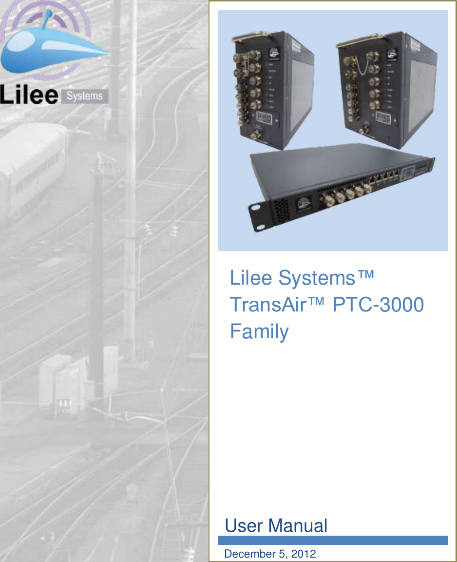
Lilee Systems TRANSAIRP3001 TRANSAIR PTC-3001 User Manual
Lilee Systems, Ltd. TRANSAIR PTC-3001 Users Manual
UserManual.wiki
>
Lilee Systems
>
TRANSAIRP3001 User Manual
>
Users Manual
Contents
1.
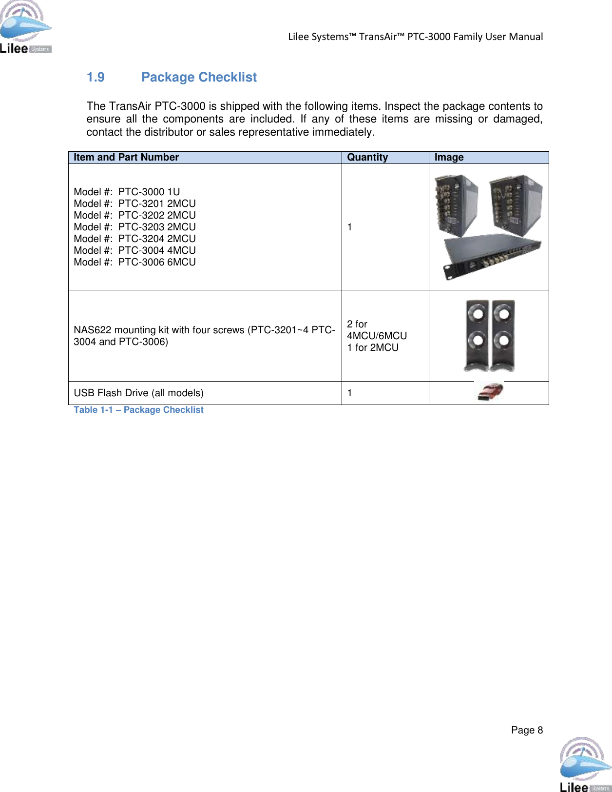
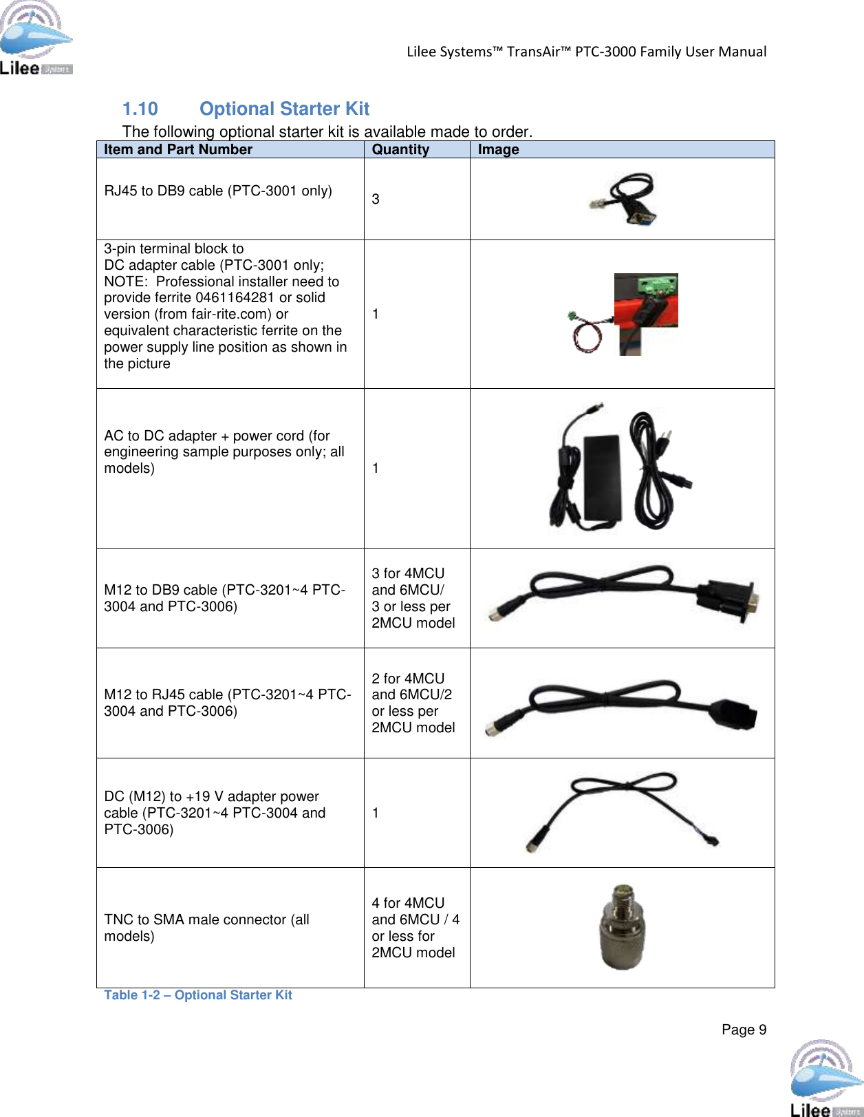
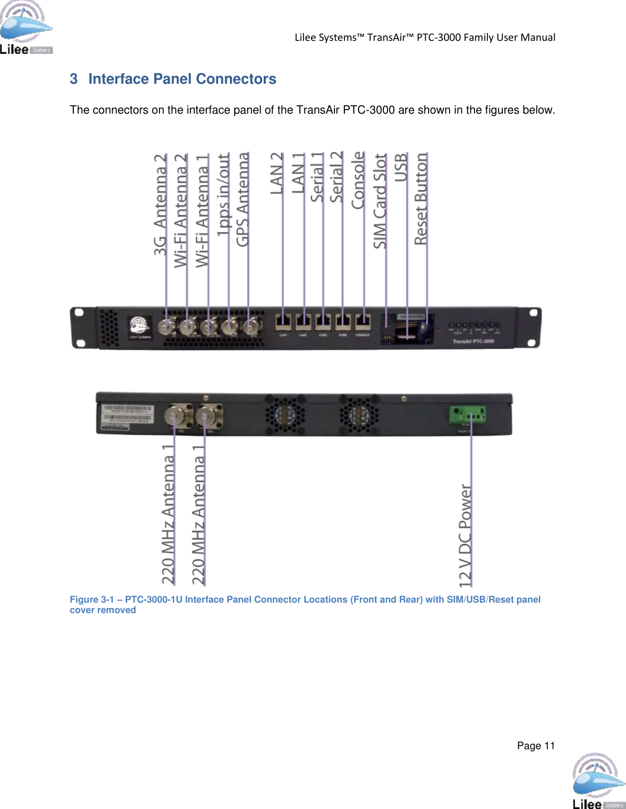
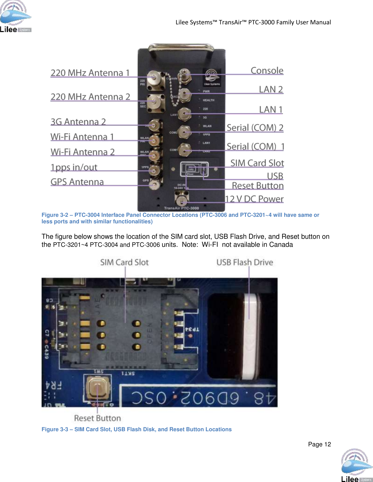
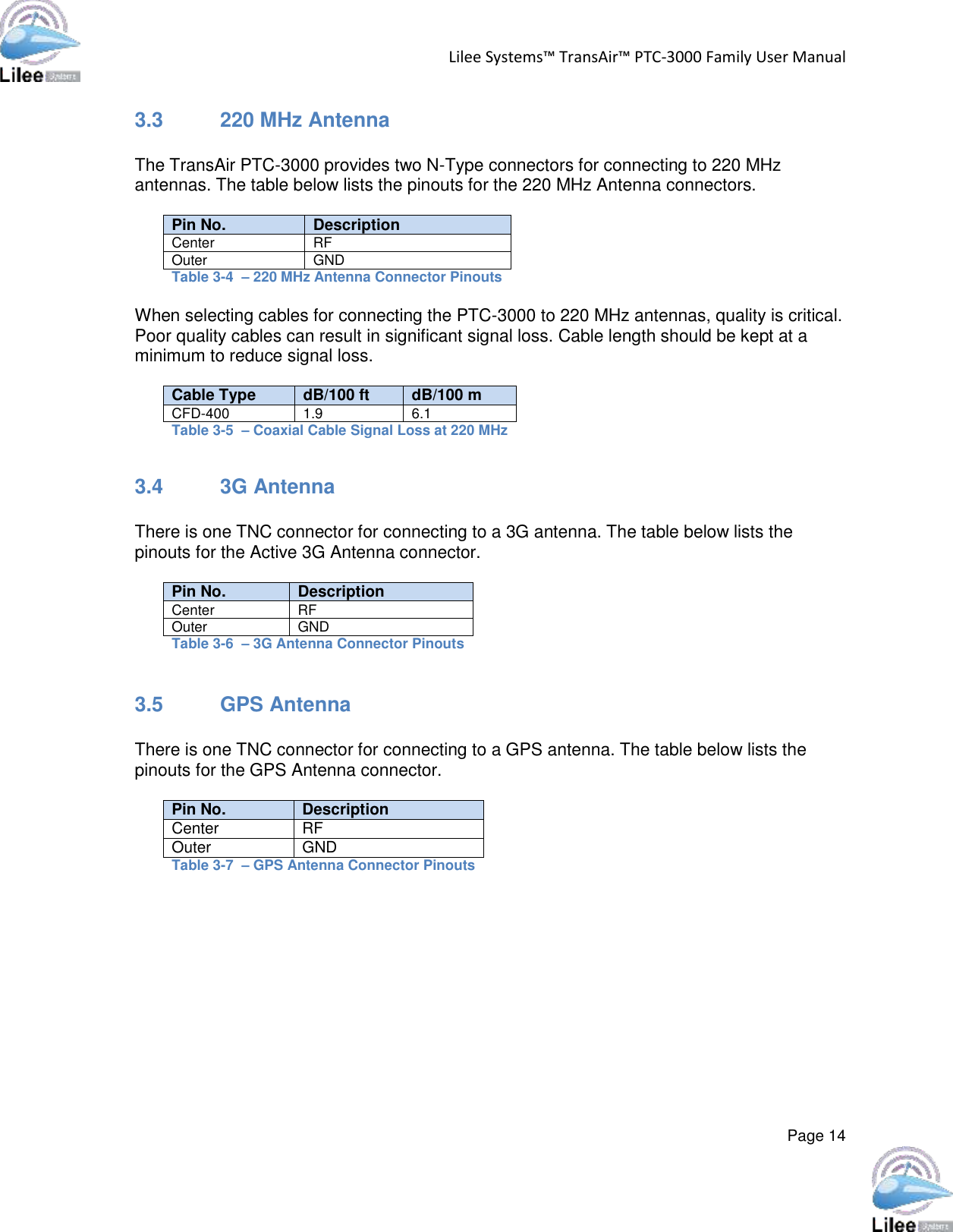
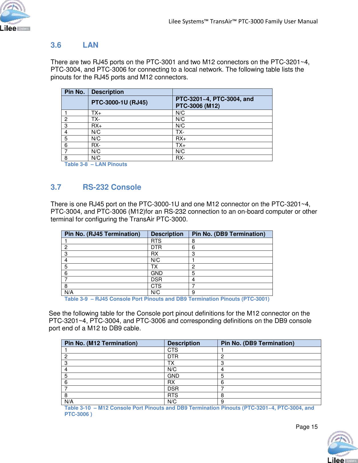
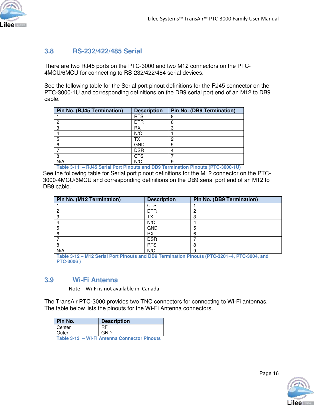
Users Manual
2.
Antenna Spec. - TransAir 3dBi Omni
3.
Antenna Spec. - 3G Antenna
4.
Antenna Spec. - Dual Yagi Antenna
5.
Antenna Spec. - Yagi Antenna
6.
Antenna Spec. - TransAir 13dBi Sector
7.
Antenna Spec. - TransAir 3dBi
8.
Antenna Spec. - Wifi Antenna
Users Manual
Navigation menu
Upload a User Manual
Namespaces
Wiki Guide
HTML
PDF
Info
Views
User Manual
Discussion / Help
Navigation