LightLab Imaging C408650 RFID DOC User Manual Manual
LightLab Imaging Inc RFID DOC Manual
UserManual.wiki
>
LightLab Imaging
>
C408650 User Manual
Manual.pdf
Navigation menu
Upload a User Manual
Namespaces
Wiki Guide
HTML
PDF
Info
Views
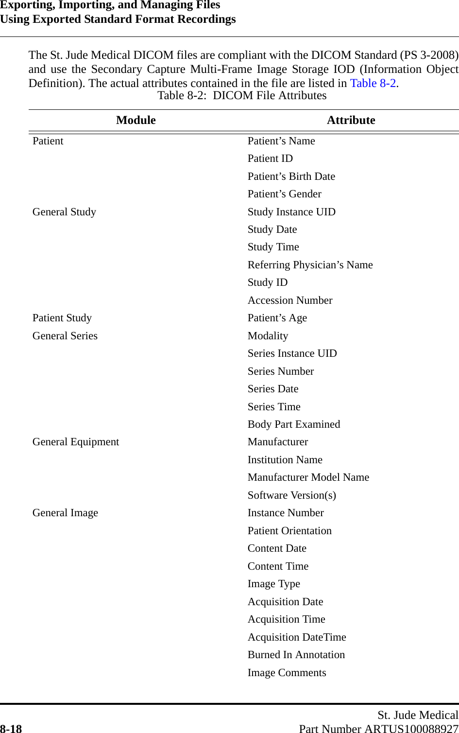
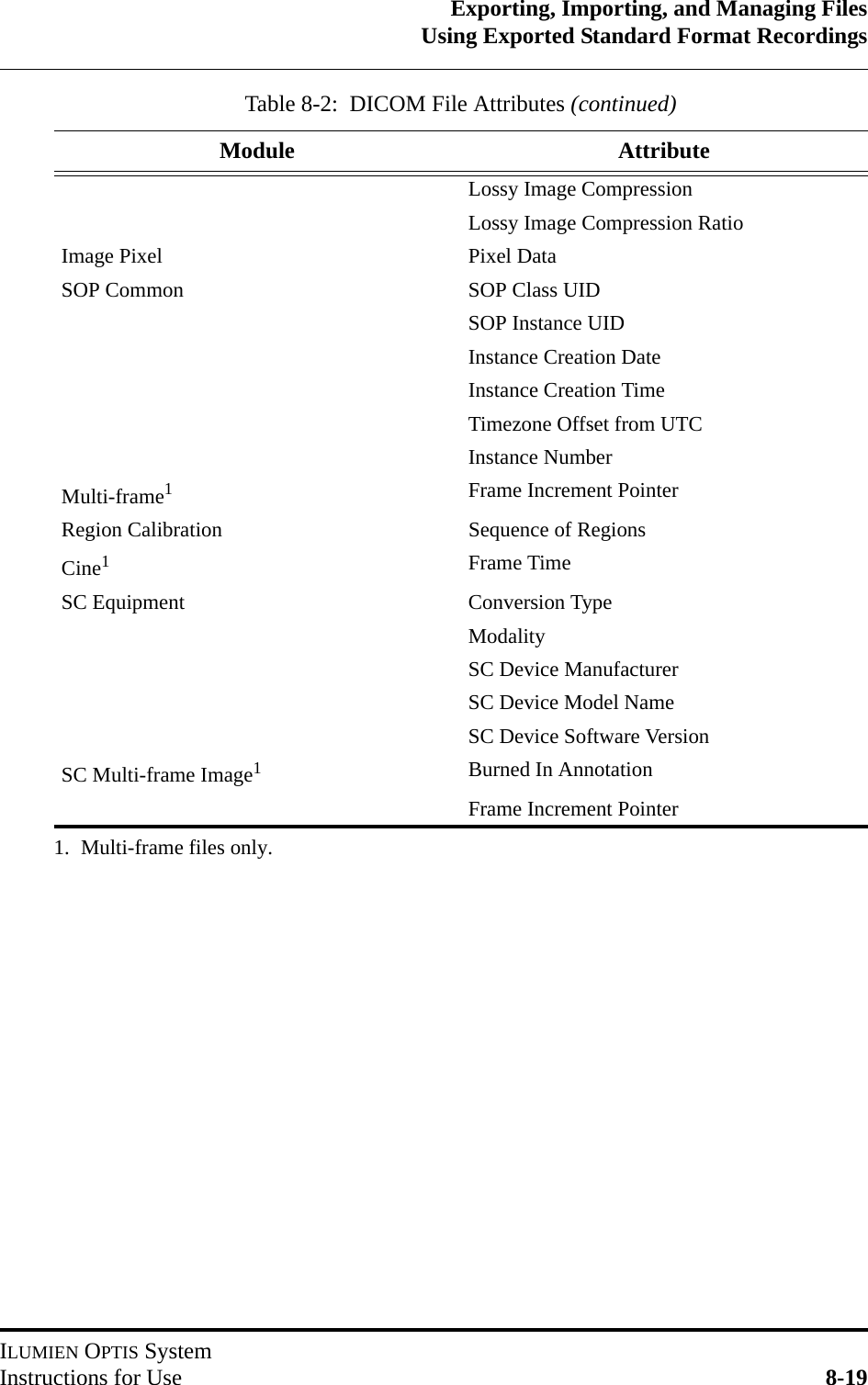
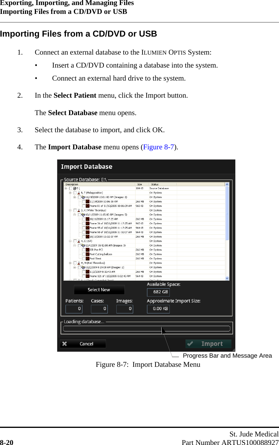
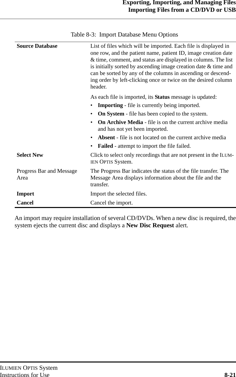
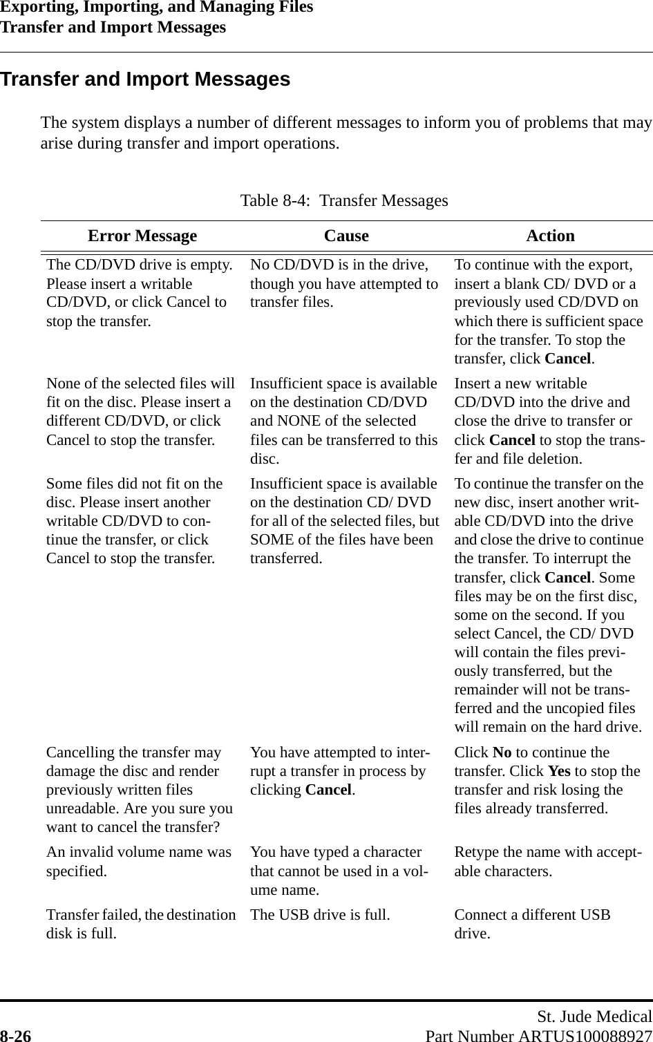
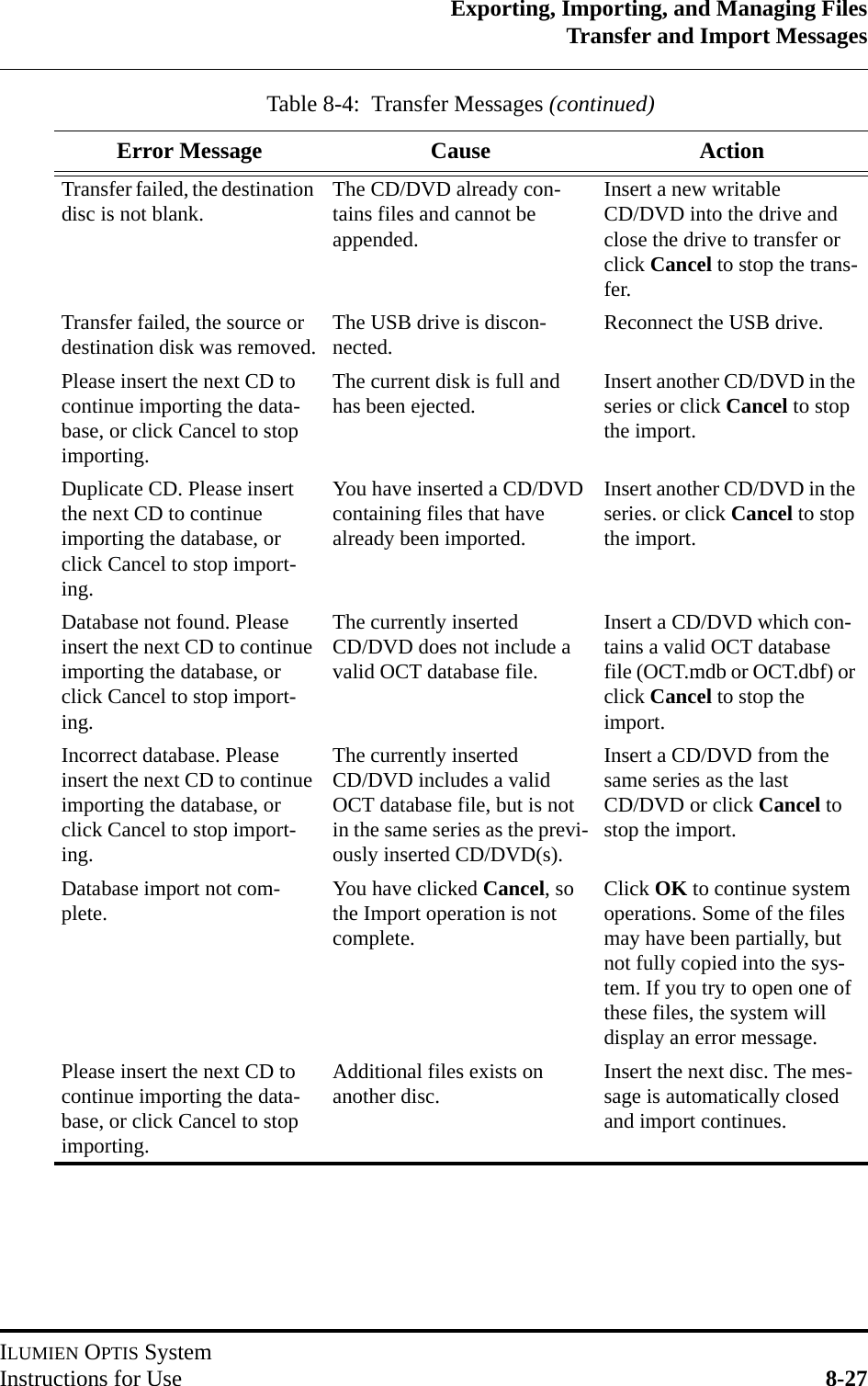
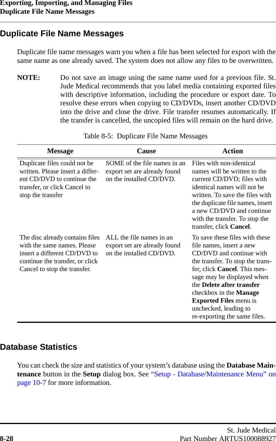
User Manual
Discussion / Help
Navigation