Lee Technology Korea LTK-25 Pager Transmitter User Manual QBTLTK 25 transmitter User s manual
Lee Technology Korea Co., Ltd. Pager Transmitter QBTLTK 25 transmitter User s manual
UserManual.wiki
>
Lee Technology Korea
>
LTK 25 User Manual
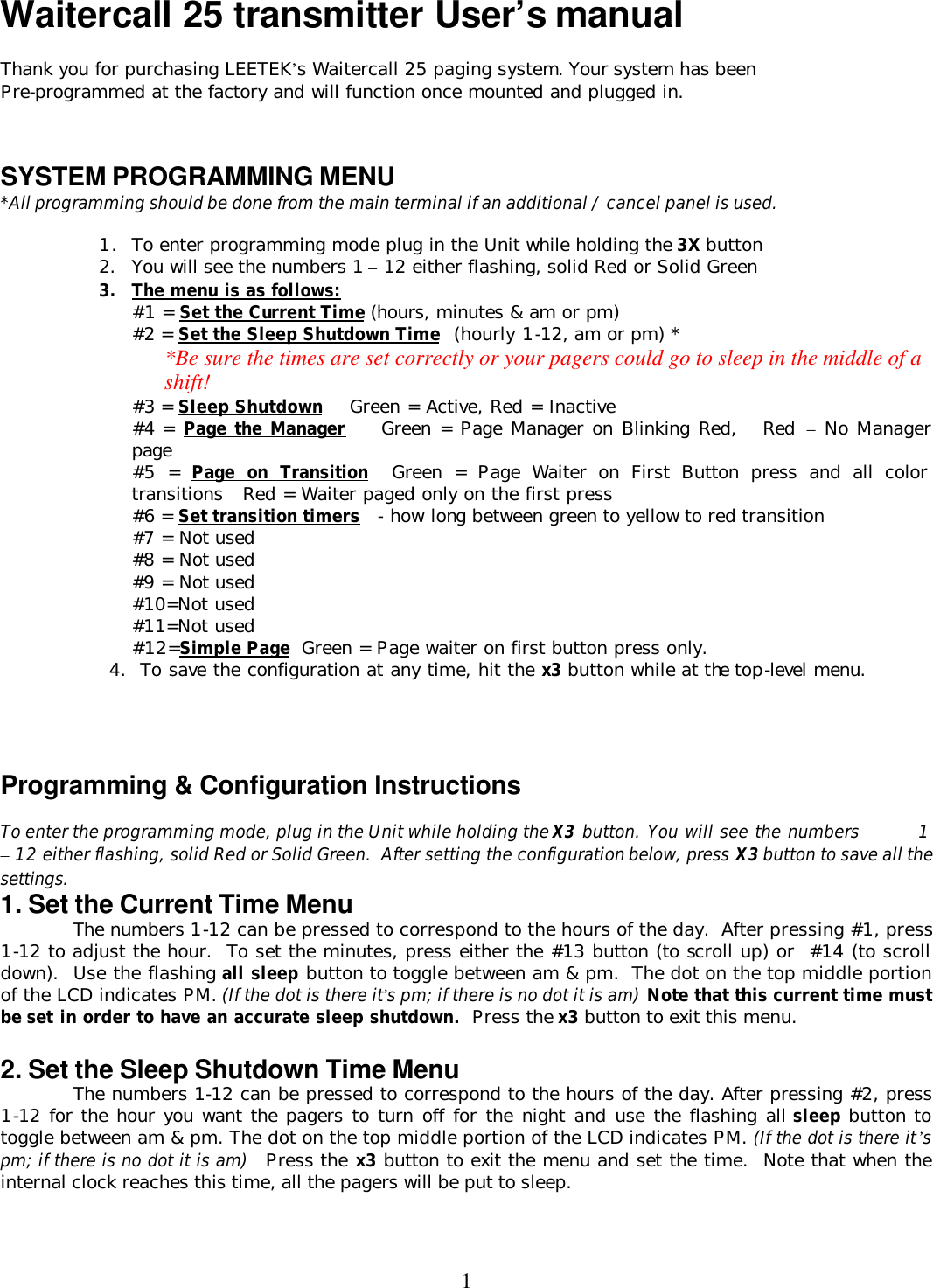
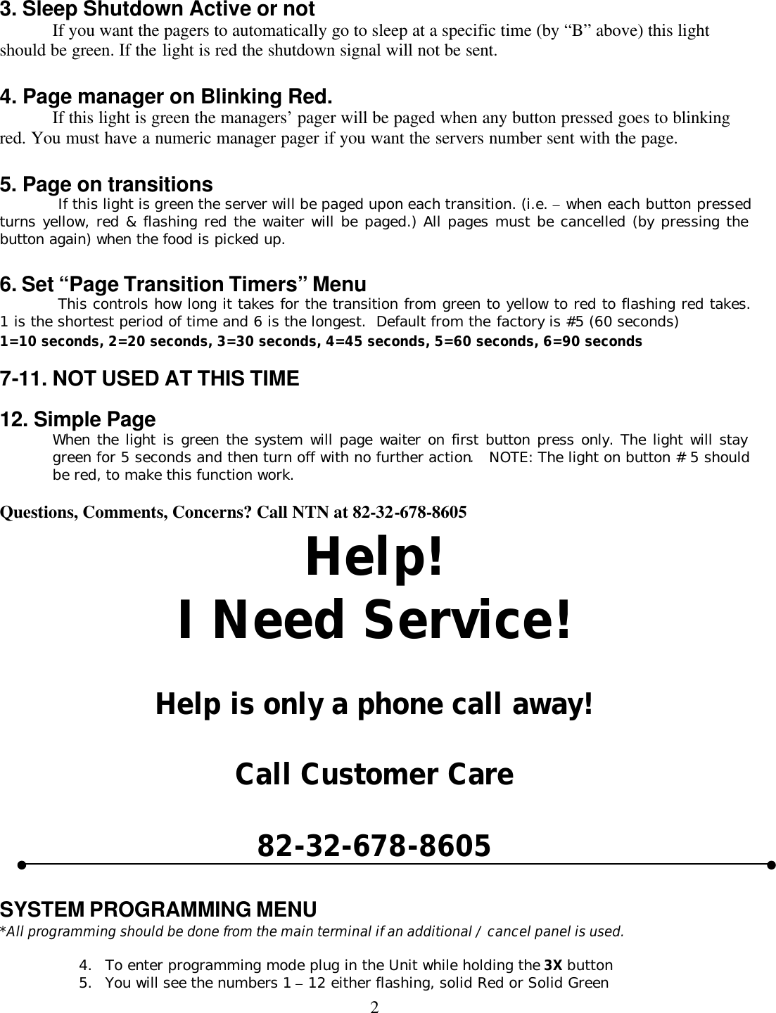
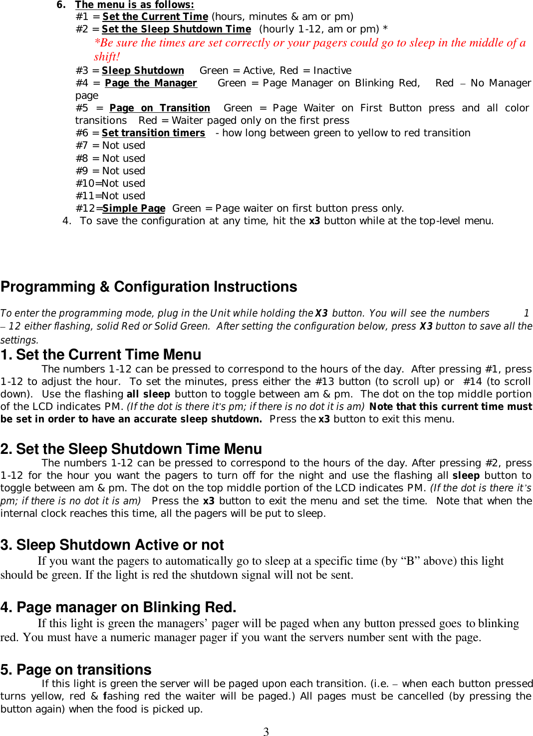
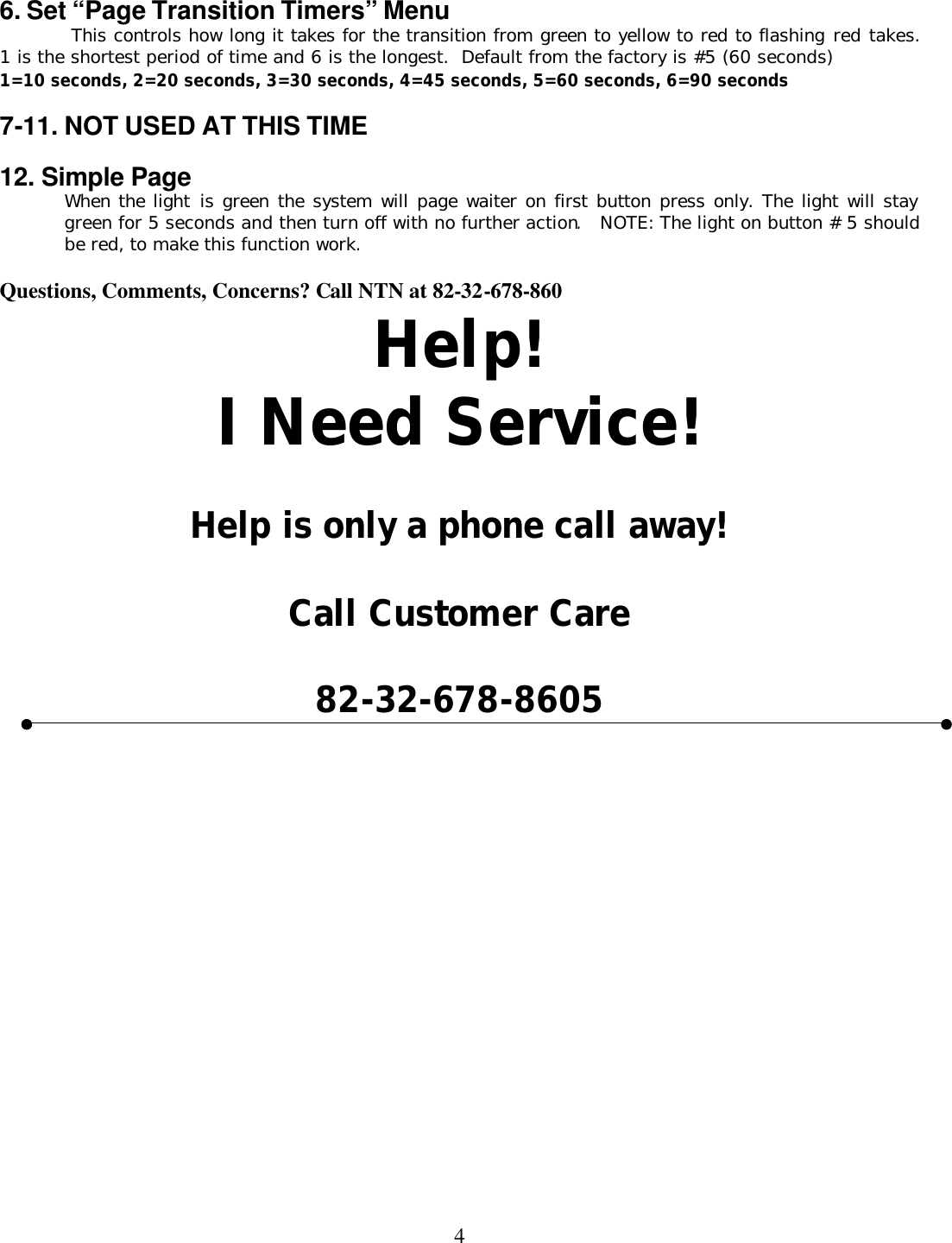
USERS MANUAL
Navigation menu
Upload a User Manual
Namespaces
Wiki Guide
HTML
PDF
Info
Views
User Manual
Discussion / Help
Navigation