LM Technologies LM78X BLUETOOTH MODULE User Manual VVXLM78X FCCID UsersManual
LM Technologies Ltd. BLUETOOTH MODULE VVXLM78X FCCID UsersManual
UserManual.wiki
>
LM Technologies
>
LM78X User Manual
Users Manual
Navigation menu
Upload a User Manual
Namespaces
Wiki Guide
HTML
PDF
Info
Views
User Manual
Discussion / Help
Navigation
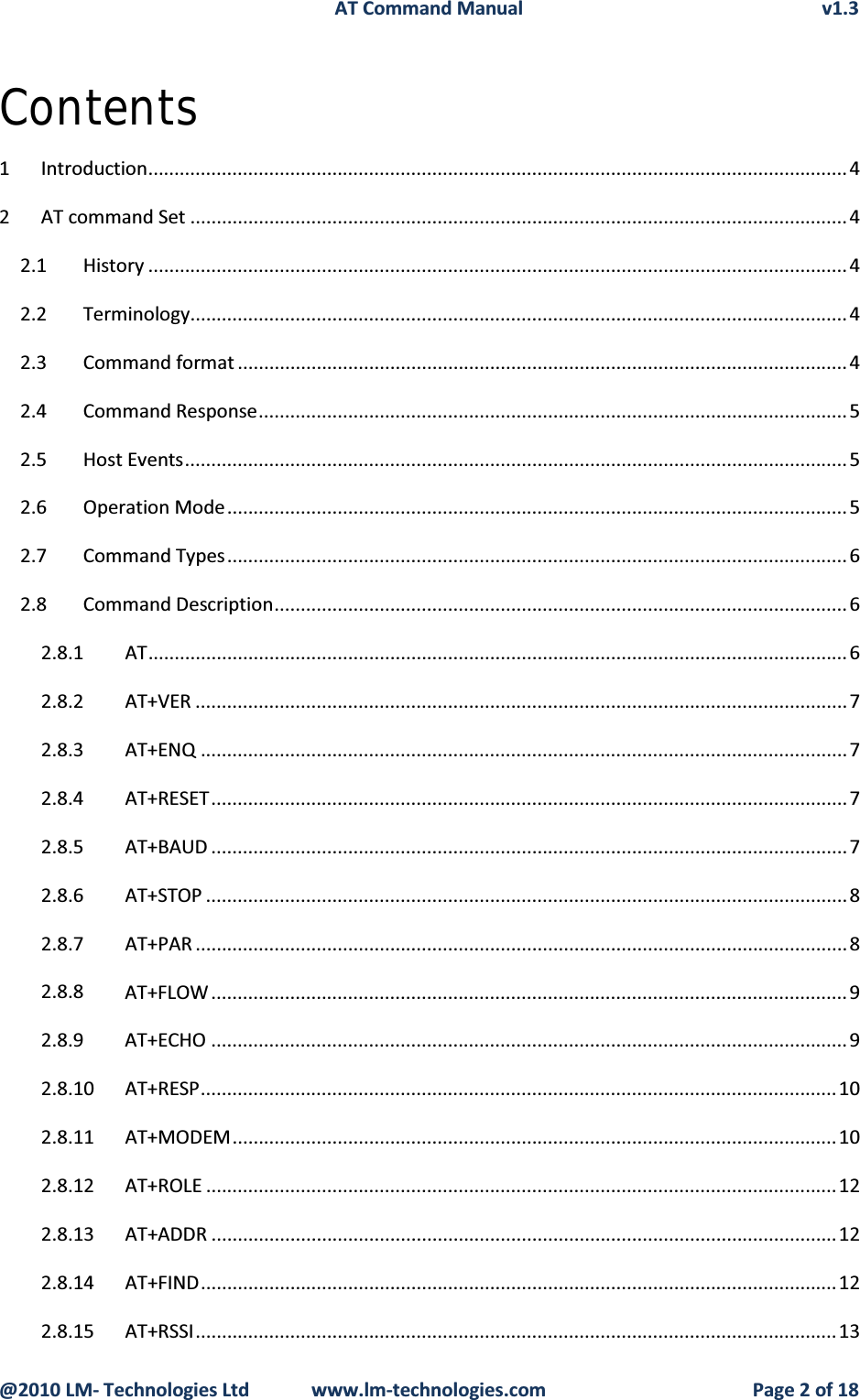
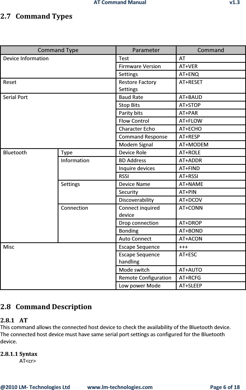
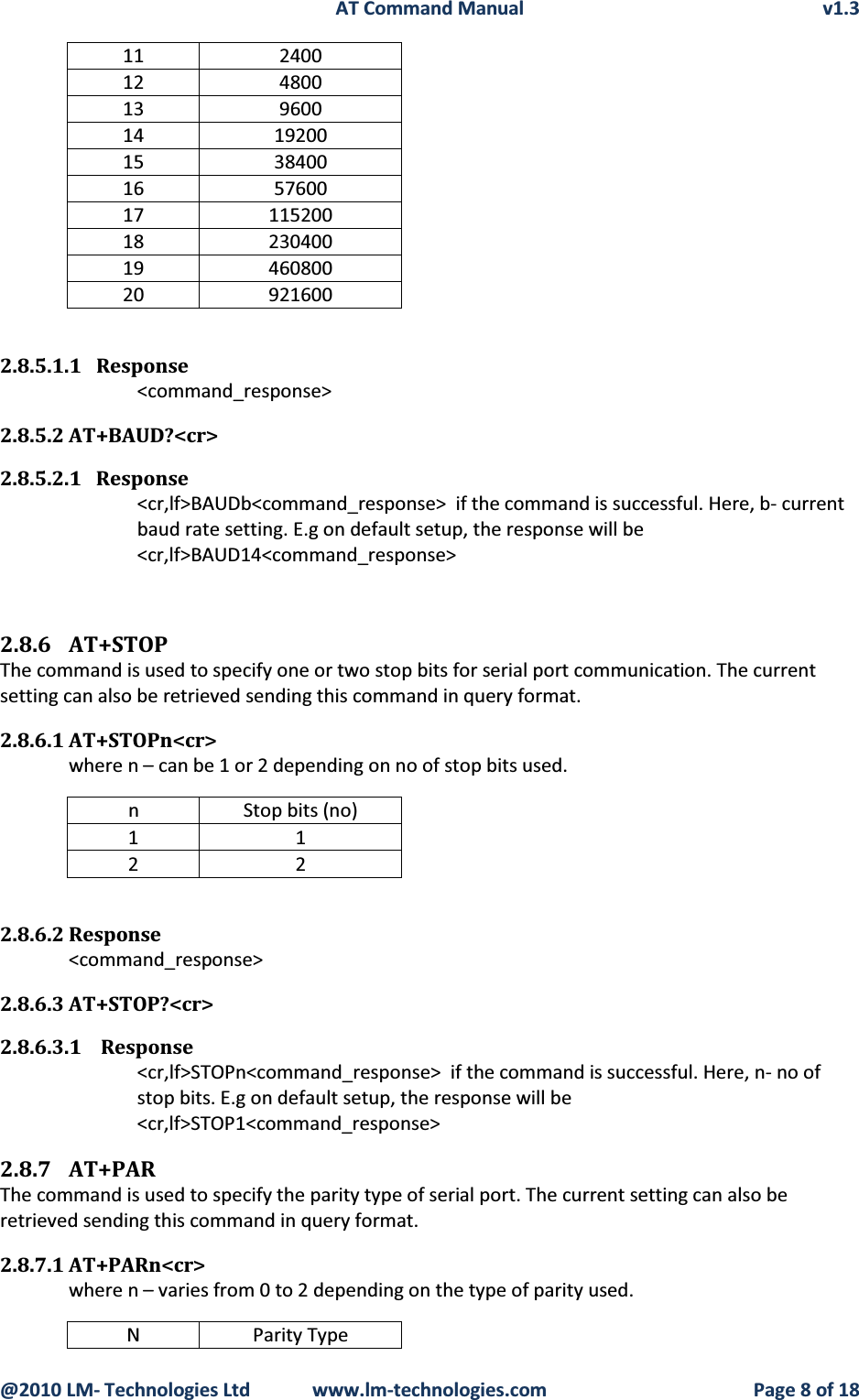
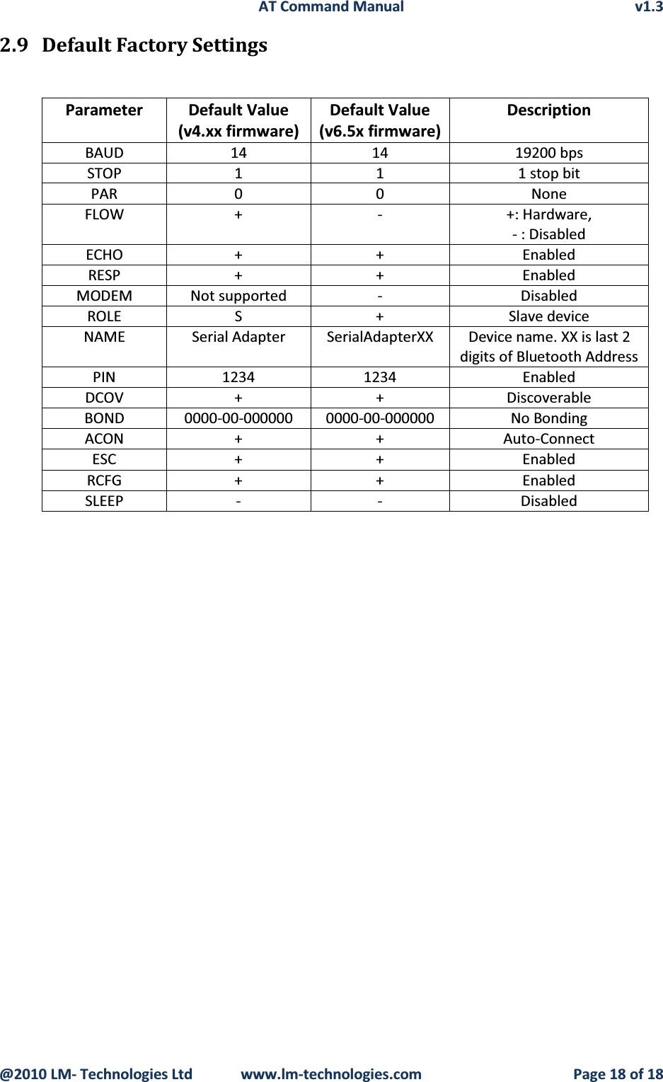
![AT Command Manual v1.3@2010 LM- Technologies Ltd www.lm-technologies.com Page 7 of 182.8.1.2 Response<command_response>2.8.2 AT+VERReturns the device firmware version2.8.2.1 SyntaxAT+VER<cr>2.8.2.2 Response<cr,lf>FW VERSION: vX.YZ<command_response>Where X: Major release of device firmware YZ: Minor release/updates of device firmwaree.g. FW VERSION: v4.502.8.3 AT+ENQList all the device information and all the settings along with their brief description. The settings include serial port, Bluetooth related and other misc settings.2.8.3.1 SyntaxAT+ENQ<cr>2.8.3.2 Response<command_response><cr,lf><Parameter Setting, Brief Description><cr,lf> for each parameter.e.g. device role setting will be listed as “<cr,lf>ROLEM, MASTER ROLE <cr,lf>”. All other settings and other device information is listed in similar manner.2.8.4 AT+RESETThis command is used to restore the default factory settings and perform device reboot. The default factory settings are listed in table [reference]2.8.4.1 SyntaxAT+RESET<cr>2.8.4.2 Response<command_response>2.8.5 AT+BAUDThe command allows setting the baud rate for the serial UART port. The current baud rate setting can also be retrieved by sending this command in query format.2.8.5.1 AT+BAUDb<cr>where b – varies from 10 to 20 for different baud rates. The baud rate varies from 1200bps to 921 Kbps. e.g. To set 19200 as UART baud rate, the command is AT+BAUD14<cr>b Baud rate (bps)10 1200](https://usermanual.wiki/LM-Technologies/LM78X/User-Guide-1644225-Page-9.png)