LINKSYS WRT610NV2 Simultaneous Dual-Band Wireless-N Gigabit Router User Manual WRT610N User Guide
LINKSYS LLC Simultaneous Dual-Band Wireless-N Gigabit Router WRT610N User Guide
LINKSYS >
Contents
- 1. Manual Part 1
- 2. Manual Part 2
Manual Part 1
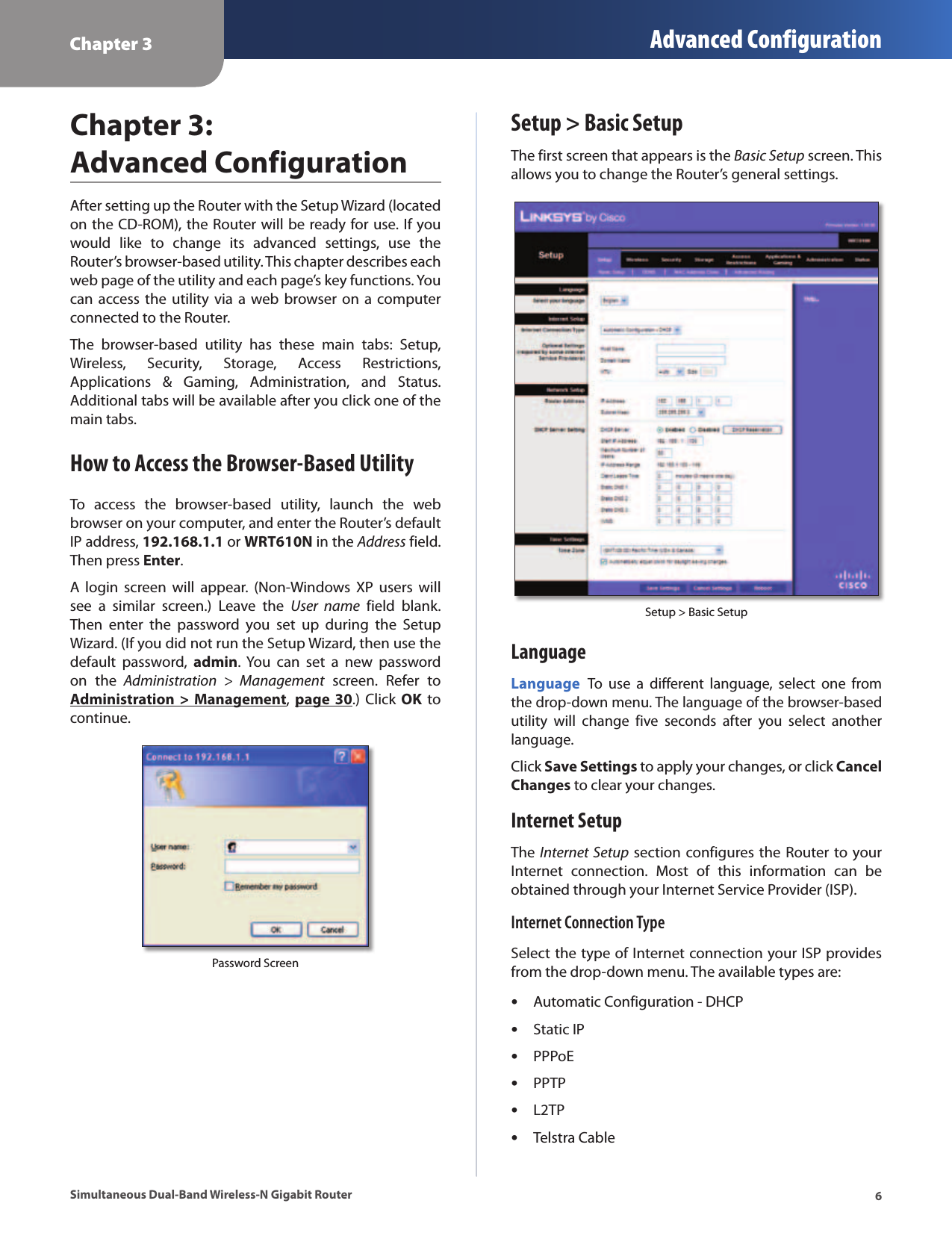
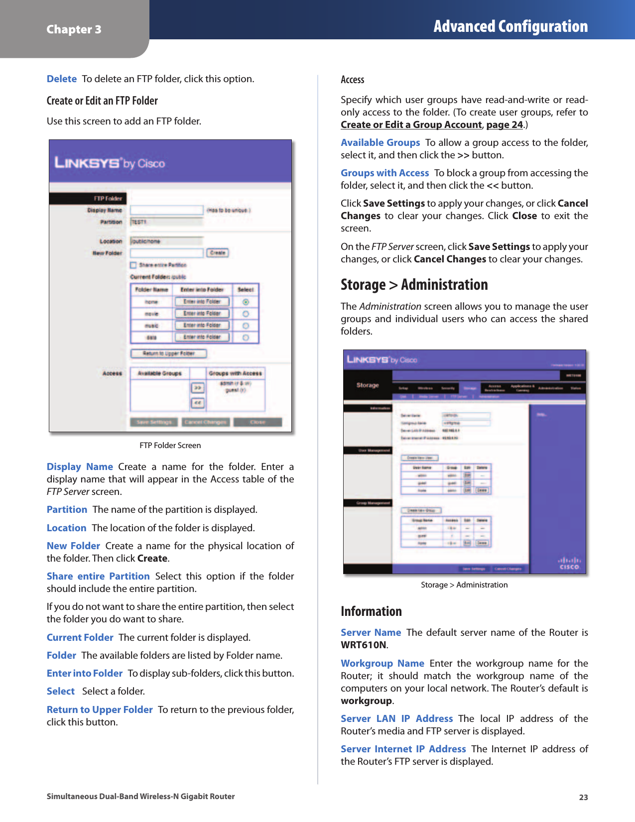
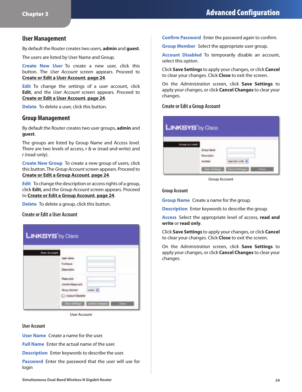
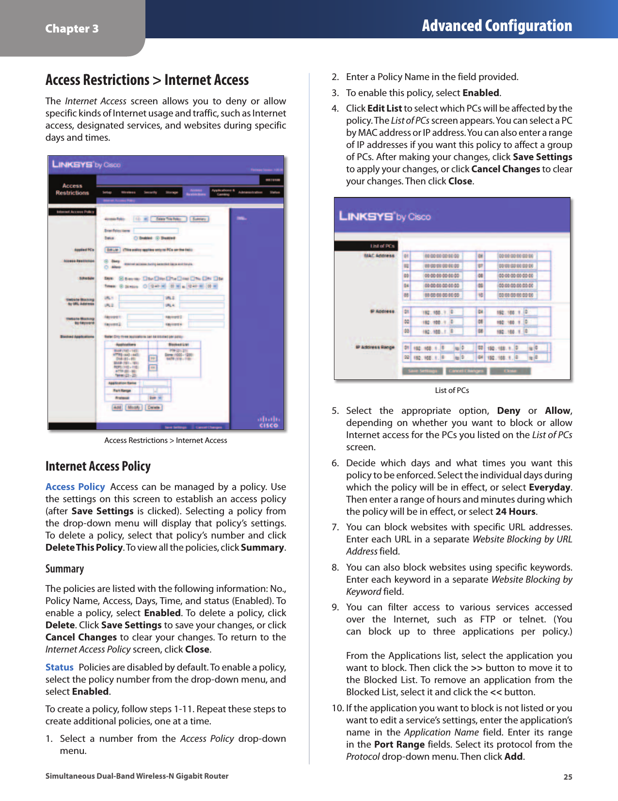
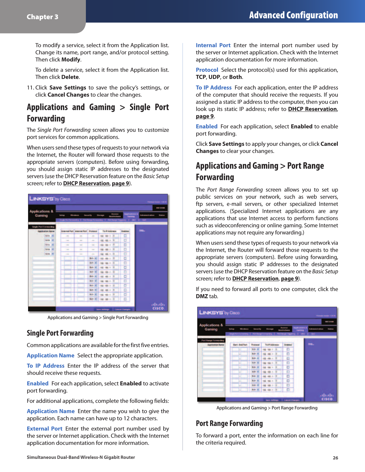
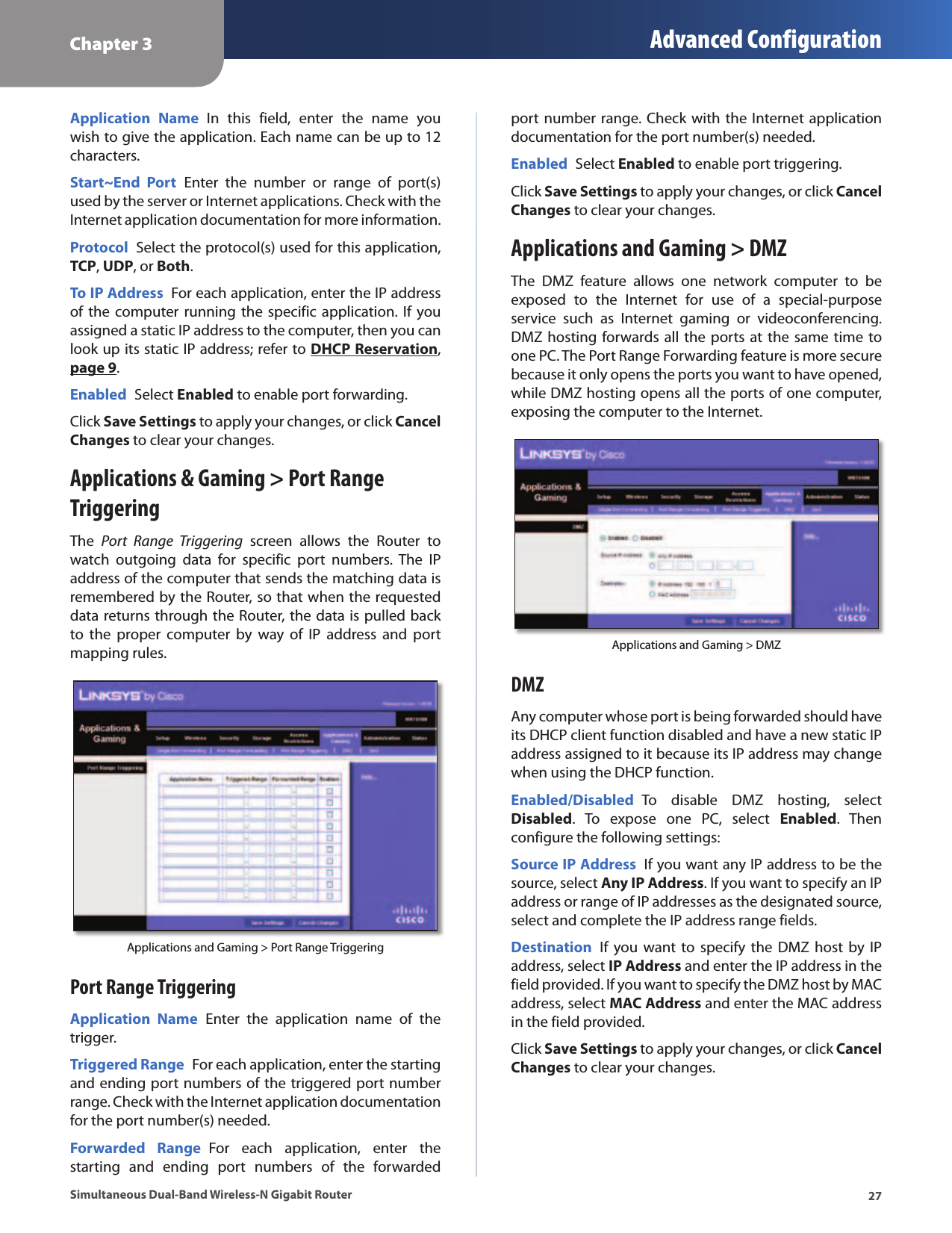
![Chapter 3 Advanced Configuration14Simultaneous Dual-Band Wireless-N Gigabit Router3. After the client device has been configured, click OK on the Router’s Wi-Fi Protected Setup screen. Then refer back to your client device or its documentation for further instructions.Method #3 Use this method if your client device asks for the Router’s PIN number. 1. On the client device, enter the PIN number listed on the Router’s Wi-Fi Protected Setup screen. (It is also listed on the label on the bottom of the Router.)2. After the client device has been configured, click OK on the Router’s Wi-Fi Protected Setup screen. Then refer back to your client device or its documentation for further instructions.The Wi-Fi Protected Setup Status, Network Name (SSID), Security, and Passphrase are displayed at the bottom of the screen.NOTE: If you have client devices that do not support Wi-Fi Protected Setup, note the wireless settings, and then manually configure those client devices.Wireless > Wireless SecurityThe wireless security settings configure the security of your wireless network(s). The Router supports the following wireless security options: WPA2 Personal, WPA Personal, WPA2 Enterprise, WPA Enterprise, RADIUS, and WEP. WPA (Wi-Fi Protected Access) is a stronger security standard than WEP (Wireless Equivalent Privacy), and WPA2 is even more secure than WPA. RADIUS is Remote Authentication Dial-In User Service.5 GHz or 2.4 GHz Wireless SecurityWireless security is strongly recommended, and WPA2 is the strongest method available. Use WPA2 if it is supported by all of your wireless devices.Security ModeSelect the security method for each wireless network. If you do not want to use wireless security, keep the default, Disabled.WPA2 PersonalNOTE: If you are using WPA2 or WPA, each device in your wireless network MUST use the same WPA method and shared key, or else the network will not function properly.]WPA2 PersonalEncryption WPA2 supports two encryption methods with dynamic encryption keys, AES or WPA-TKIP/WPA2-AES. The default is AES.Passphrase Enter a passphrase of 8-63 characters. Key Renewal Enter a Key Renewal period, which instructs the Router how often it should change the encryption keys. The default is 3600 seconds.WPA PersonalNOTE: If you are using WPA2 or WPA, each device in your wireless network MUST use the same WPA method and shared key, or else the network will not function properly. WPA PersonalEncryption WPA uses TKIP, an encryption method with dynamic encryption keys.Passphrase Enter a passphrase of 8-63 characters. Key Renewal Enter a Key Renewal period, which instructs the Router how often it should change the encryption keys. The default period is 3600 seconds.](https://usermanual.wiki/LINKSYS/WRT610NV2.Manual-Part-1/User-Guide-1146560-Page-16.png)