Koden Electronics RB719A Marine Radar RA55 User Manual C4 Chap3 01
Koden Electronics Co., Ltd Marine Radar RA55 C4 Chap3 01
UserManual.wiki
>
Koden Electronics
>
RB719A User Manual
>
RB719A C4
Contents
1.
Cover
2.
C0
3.
C1
4.
C2
5.
C3
6.
C4
7.
C5
8.
C6
9.
C7
10.
C8
11.
C9
12.
C10
13.
C11
14.
C12
15.
C13
16.
C14
17.
C15
18.
C16
19.
C17
20.
C18
21.
C19
22.
C20
23.
C21
C4
Navigation menu
Upload a User Manual
Namespaces
Wiki Guide
HTML
PDF
Info
Views
User Manual
Discussion / Help
Navigation
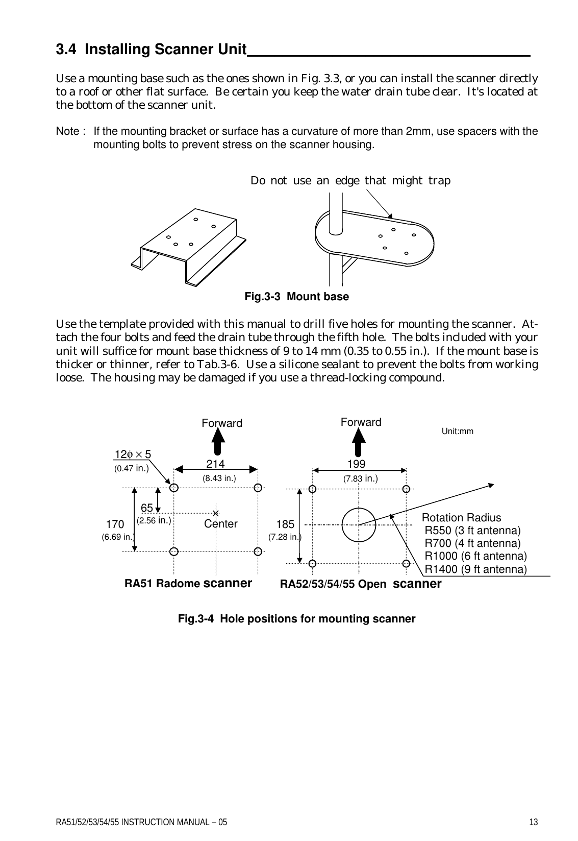
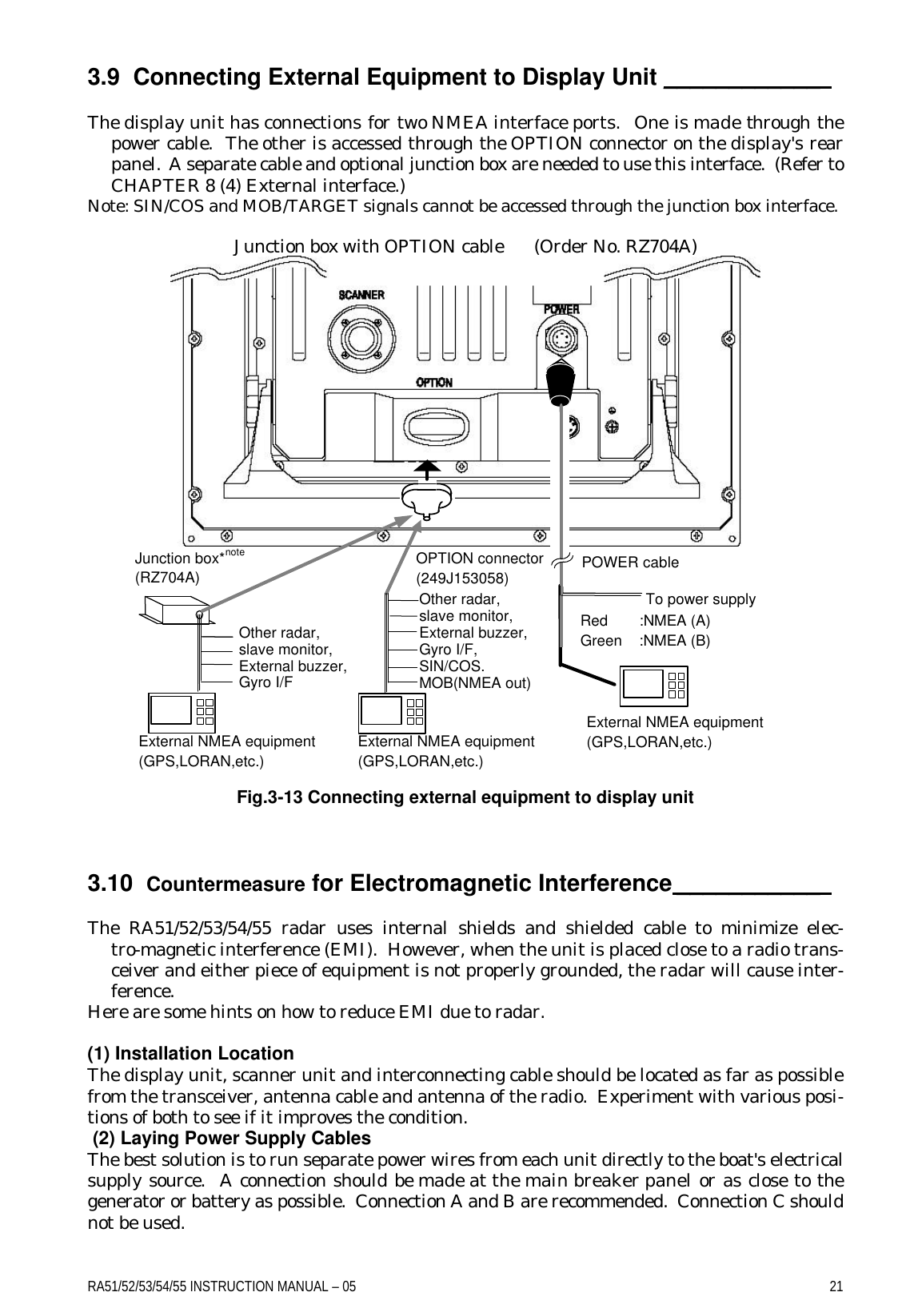
![12 RA51/52/53/54/55 INSTRUCTION MANUAL – 05 3.3.3 Shifting away from obstacles • Shifting from keel line By shifting the scanner position from the keel line to the starboard side of the boat, it is possible to move shadow zones to the port side. This makes it possible to keep a clear view to the bow. The distance to be shifted can calculated using the following equation: Ls=0.4R+D/2 [m] (when R<15m) Ls=0.025R+D/2 [m] (when R>=15m) where Ls = distance to be shifted from keel line D = diameter of obstacle on keel line R = distance from scanner to obstacle Fig.3-1 Shifting from keel line ‚ Obtaining sufficient dip angle Raise the scanner position so that there is a sufficient dip angle θ available between the line of sight from the scanner to the obstacle and the horizontal line. By raising the dip angle above 5°, it is possible to prevent mid- and long-distance shadow zones. The radar cannot detect objects below the line of sight. Fig.3-2 Obtaining sufficient dip angle Ls R D Scanner Unit Obstacle Keel line Horizontal line Line of sight θ](https://usermanual.wiki/Koden-Electronics/RB719A.C4/User-Guide-267651-Page-4.png)