Kaba Ilco 58005900 RFID Card Reader User Manual System Analysis Firmware
Kaba Ilco Corporation RFID Card Reader System Analysis Firmware
UserManual.wiki
>
Kaba Ilco
>
58005900 User Manual
User Manual
Navigation menu
Upload a User Manual
Namespaces
Wiki Guide
HTML
PDF
Info
Views
User Manual
Discussion / Help
Navigation

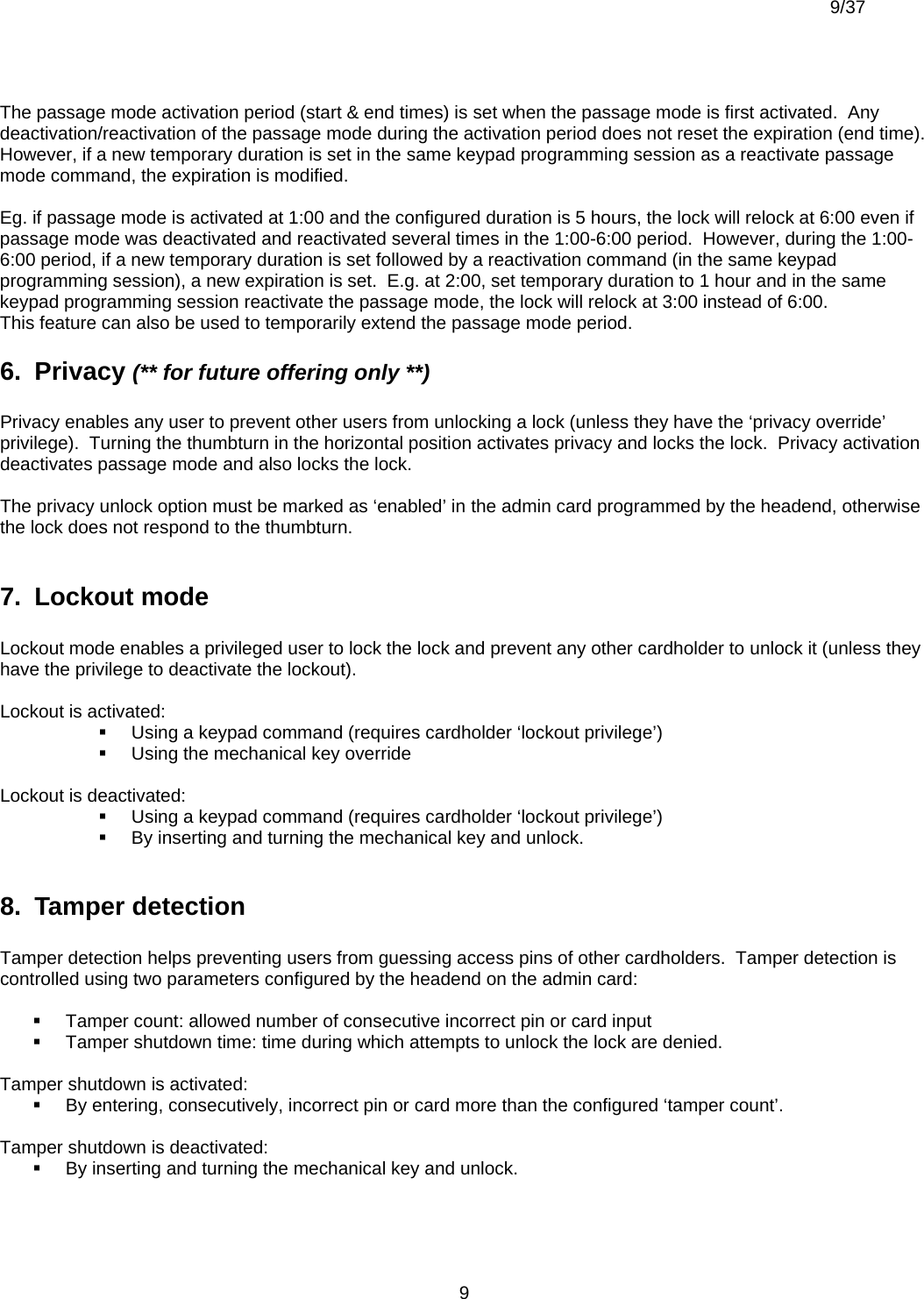
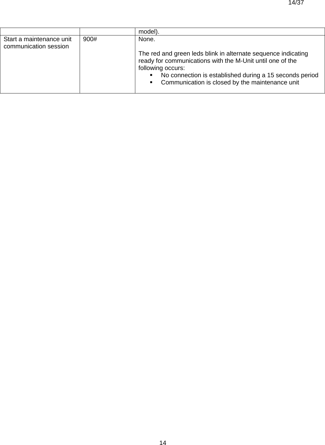
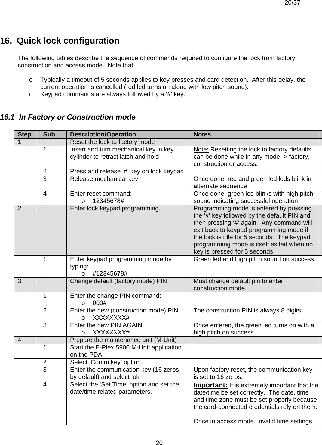
![6/37 62. Lock types The E-Plex 5900 currently supports one of the two lock types with lock functions as: Cylindical lock without thumbturn, supporting an “Entry” lock function. Cylindrical or mortise lock with privacy thumbturn (with deadbolt for mortise), supporting a “Privacy” lock function [** this model is for future offering only; currently not available “”] The type of lock is configured through this access control system’s “Admin card” programmed by the on-line headend system. Currently the E-Plex supports the DESFire card as user credential which is an ISO 14443A compatible read/write RF card. It is important that the lock type be correctly setup at the outset because detection of ‘door forced’ and ‘door open from inside’ conditions relies on it. The factory default of an E-PLex 5900 lock function is “Entry” with the lock type being a cylindrical lock without a privacy thumbturn. 3. Operation modes The lock operates in one of the following modes: Factory Construction Access Bootloader 3.1 Factory mode Out of the box, the lock is in factory mode with a lock function as “Entry” and with an 8-digit PIN to open the lock as 12345678. This mode provides the operator with a known initial state. The operator can: Unlock the lock by entering the default PIN on the keypad: 12345678 Change the default PIN Validate the lock electronics hardware components In this mode, only the factory default PIN of 12345678 will open the lock but not users’ DESFire cards. 3.2 Construction mode Once the default PIN is changed, the lock enters construction mode. This mode is used until the lock can be configured using an admin card (which requires the enrollment system to be in place at the headend access control system). The operator can: Unlock the lock by entering the new construction mode PIN on the keypad Communicate with a maintenance unit (M-Unit) which is typically a Windows Mobile 5.0 compatible handheld PDA, using the default communications key (16 zeros) to access the following functionalities: o Set the date/time, daylight saving time info and time zone o Update the bootloader o Update the firmware Use one of the following lock keypad commands o Change PIN](https://usermanual.wiki/Kaba-Ilco/58005900/User-Guide-842352-Page-6.png)

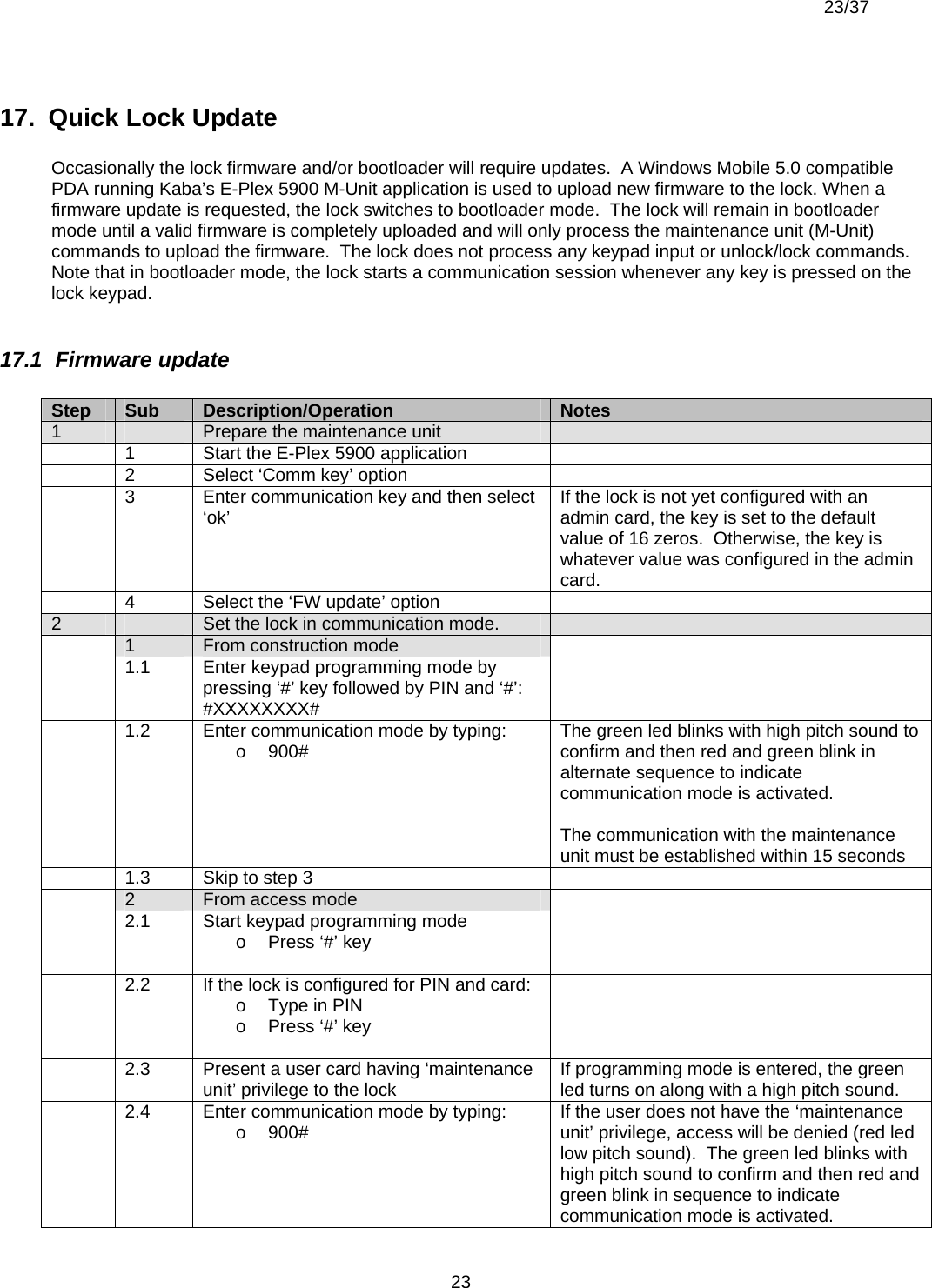
![10/37 109. Remote Unlock option (*must be installed to operate*) If installed, the remote unlock option enables users to unlock the lock with a normally open, momentary on/off switch. This switch is connected to the remote unlock connector inside the lock by a 24 AWG gage twisted pair wire up to about 100 feet in length The remote unlock option must be marked as ‘enabled’ in the admin card programmed by the headend system, otherwise the lock will not respond to the remote unlock switch. When enabled, remote unlock can be used to unlock the door during: Tamper shutdown However it will not unlock the lock: During lockout [When privacy is enabled for privacy locks; ** future**] 10. Door Ajar Sensing option (*must be installed to operate*) If installed, the door ajar sensing option senses the door opened (and then door closed) status when opened from outside (ingress); and also the door opened status when opened from inside (egress). In either case the door ajar events are audited in the lock’s memory and passed on to the headend system via the admin card as logged entries. In factory mode only, the lock will also visually indicate occurrences of these events: an alternate red and green flash sequence for an egress, a double green led flash when door is opened from outside and a double red led flash when it is closed. 11. Resetting the lock to factory defaults The lock can be reset to factory defaults at any time by following this procedure. Warning: When a hard reset like this is performed, all newly programmed lock configuration parameters, user access privilege policies etc will be erased from the lock memory and the lock will default to the factory default lock parameters and the factory default PIN of 12345678. However, the current date & time will not be altered. 1) Insert and turn mechanical override key to retract latch and hold, 2) Press key ‘#’ and release key override within 5 seconds 3) While red and green led flash alternately, press sequence ‘12345678#’ (if successful, green led flashes twice with high pitch beep) and the lock is reset to factory defaults. Note that audit logs are not erased by this procedure. 12. Mechanical key override The key override is used to: Mechanically unlock the lock (insert and turn the key to retract the latch) Reset the lock to factory defaults (see ‘Resetting the lock to factory defaults’ section) Reset tamper shutdown (see ‘Tamper shutdown’ section) Deactivate lockout (see ‘lockout mode’ section)](https://usermanual.wiki/Kaba-Ilco/58005900/User-Guide-842352-Page-10.png)

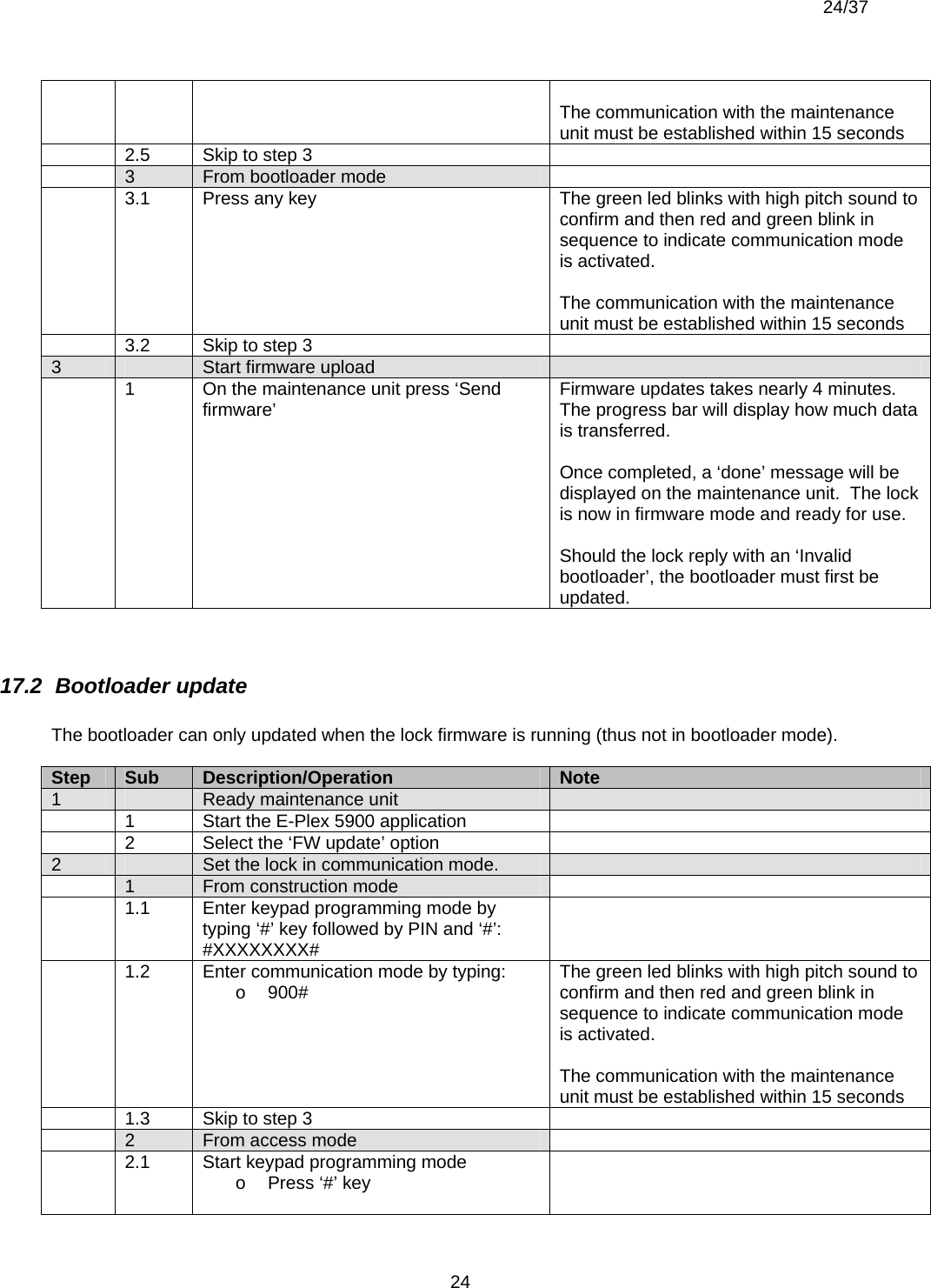
![19/37 1914.4 Performing Diagnostics The M-Unit can query the lock for a collection of useful status info from the lock including a validity check on the lock electronics, green and red leds and the buzzer. Click on “Get” to display the results: The Diagnostics will repeat in a continuous loop until it is stopped either by removing the M-Unit PDA from the lock vicinity or by selecting the “Stop” button. This loop function is useful for verifying all the keys on the lock keypad etc. [Note: The current beta version of the M-Unit software will only take a “snapshot” of the diagnostics status once and will display it as shown above. There is no “Stop” button and no continuous loop diagnostics at this time]. 15. Audit Logs The E-Plex 5900 keeps a log entry for every transaction or event encountered in its memory. The audit log entries are stored in a circular list, where newer ones overwrite older ones. Events like any DESFire card user access, passage mode on/off status etc are logged and transferred to the headend system automatically. Note that audit og entries in the lock are never erased from the lock; the only time an audited event gets erased is when it is overwritten by a more recent event when the lock audit buffer is full. The lock can store up to 30,000 audits. For the beta version, only the last 10 audit events can be stored on a user’s card to be read on the headend system later; however, in the final version all 30,000 audited events can be transferred to the M-Unit to be processed at the headend system.](https://usermanual.wiki/Kaba-Ilco/58005900/User-Guide-842352-Page-19.png)
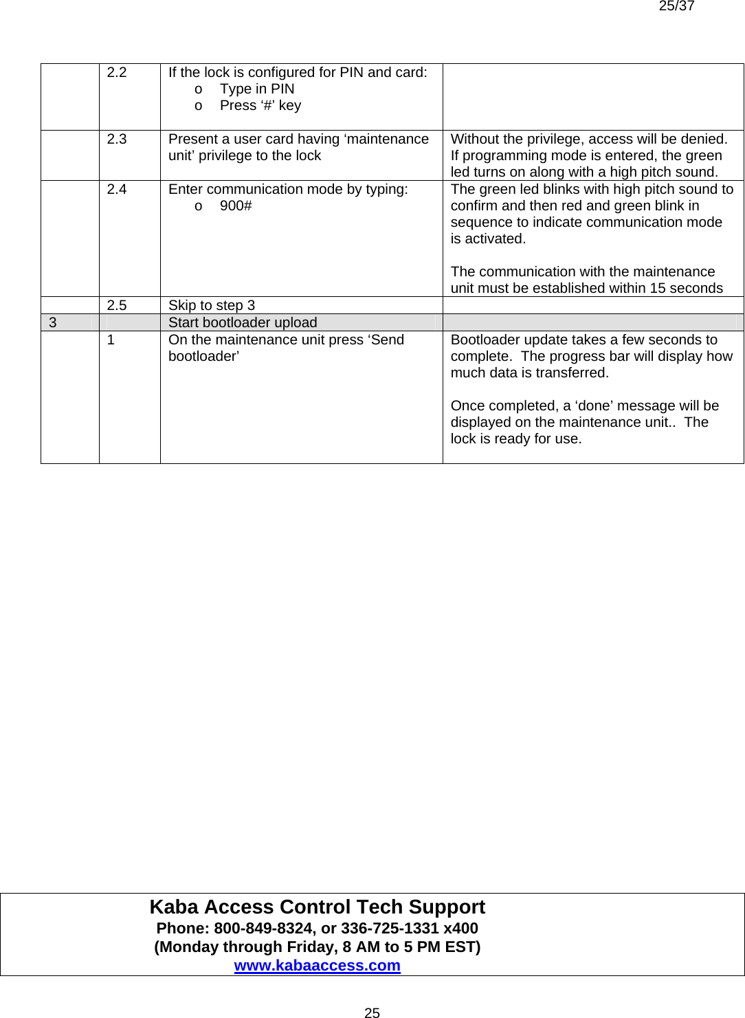
![21/37 21prevent user credential validation and so the lock will deny access to keypad programming modes (like date/time setting). 5 1 Enter communication mode by typing: o 900# The green led blinks with high pitch sound to confirm the command and then red and green leds blink in alternate sequence to indicate communication mode is activated. The communication with the maintenance unit must be established within 15 seconds 2 Click ‘Send’ on the maintenance unit ‘Set Time’ dialog Once the time is set, an ‘ok’ dialog box will be displayed and the lock will respond with a high pitch sound. 6 Configure the lock using the admin card 1 Enter the lock configuration command (where valid users will be transferred to lock via the Admin card): o 100# The green led will blink to indicate that it is waiting for the Admin card. 2 Present the Admin card to the lock Once the lock reads and processes the Admin card, the green led will turn on with a high pitch sound indicating success. [After exiting the keypad programming mode as shown on the next step, the lock is now in (user credential) access mode. A valid ISO 14443A DESFire user card will now operate the lock]. 7 Exit keypad programming mode Either exit pressing the ‘#’ key or leave the lock idle for five seconds. In the latter case, the red led turns on with a low pitch sound to indicate a timeout. 1 Press ‘#’ key Green led blinks with high pitch sound 16.2 In Access mode Step Sub Description/Operation Notes 1 Enter lock keypad programming. 1.1 Start keypad programming mode o Press ‘#’ key 1.2 If the lock is configured for PIN and card: o Type in PIN o Press ‘#’ key 1.3 Present a valid user card having ‘update using admin card’ privilege to the lock If programming mode is entered, the green led turns on along with a high pitch sound. 2 Configure the lock using the admin card 1 Enter the lock configuration command (where valid users will be transferred to lock via the Admin card): o 100# If the user does not have the ‘update using admin card’ privilege, access will be denied (red led low pitch sound). The green led will blink to indicate that it is waiting for the](https://usermanual.wiki/Kaba-Ilco/58005900/User-Guide-842352-Page-21.png)
![22/37 22admin card. 2 Present the admin card to the lock Once the lock reads and processes the card, the green led will turn on with a high pitch sound indicating success. [After exiting the keypad programming mode as shown on the next step, the lock now goes back to (user credential) access mode. A valid ISO 14443A DESFire user card will now operate the lock]. 3 Exit keypad programming mode Either exit pressing the ‘#’ key or leave the lock idle for five seconds. In the latter case, the red led turns on with a low pitch sound to indicate a timeout. 1 Press ‘#’ key Green led blinks with high pitch sound](https://usermanual.wiki/Kaba-Ilco/58005900/User-Guide-842352-Page-22.png)
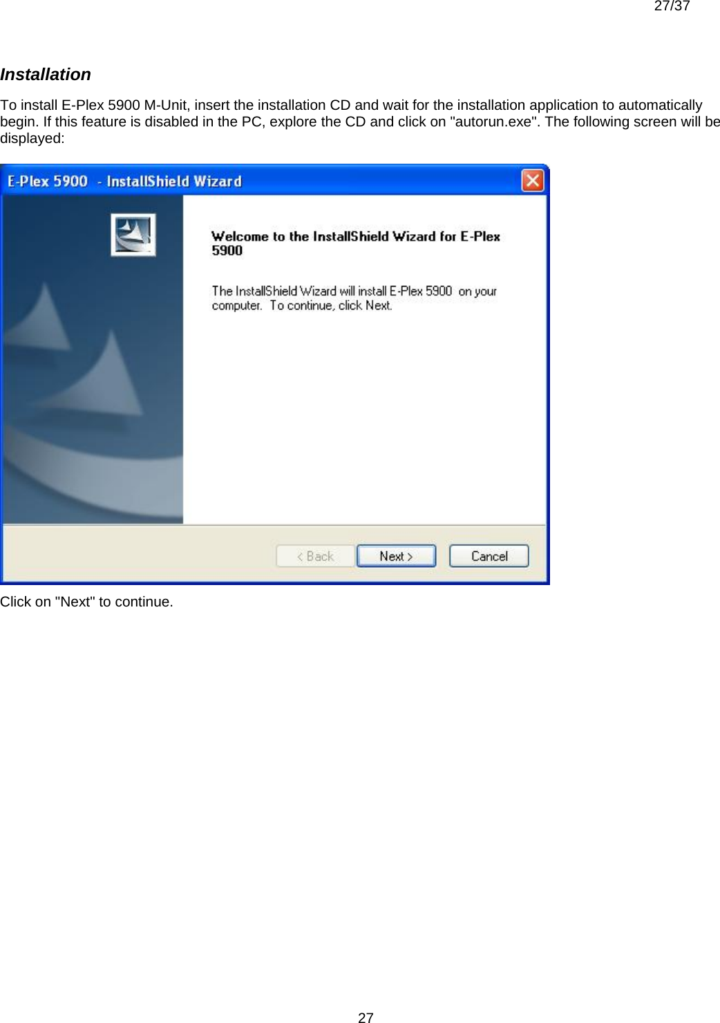
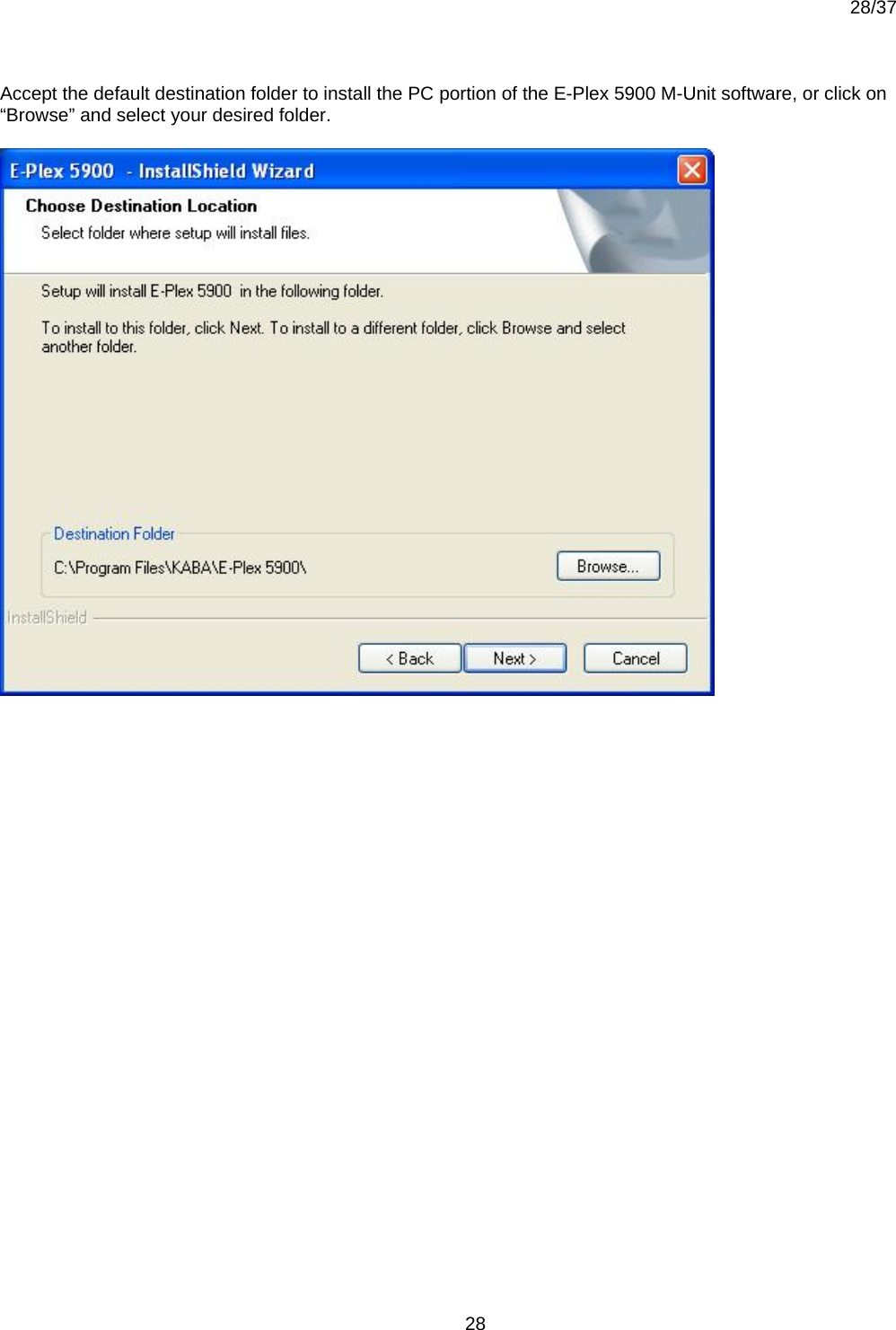
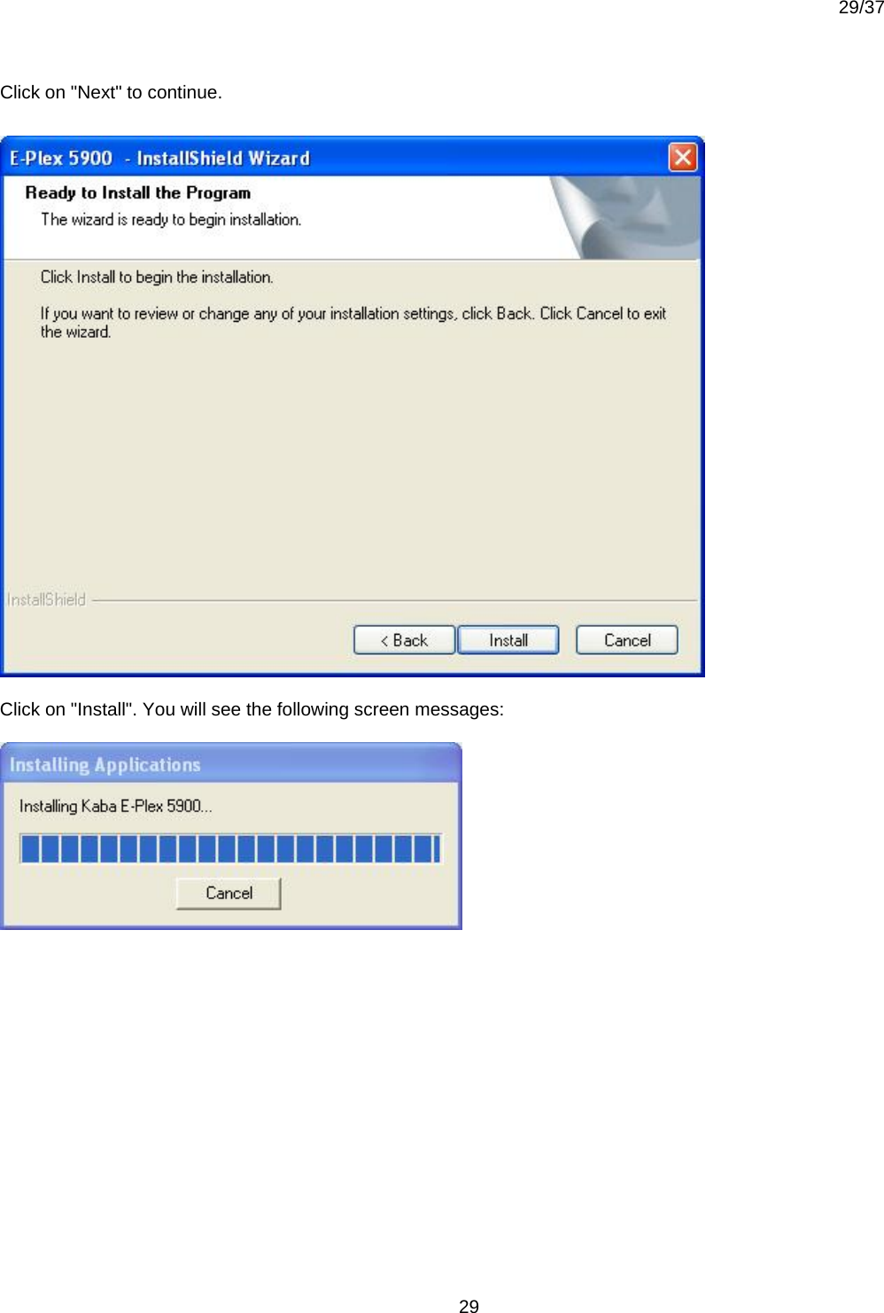
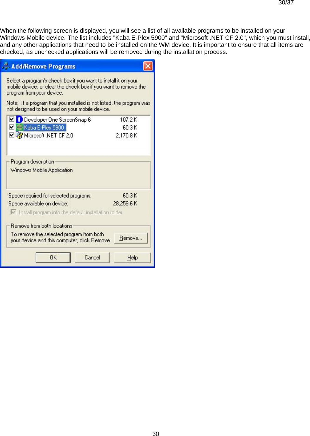
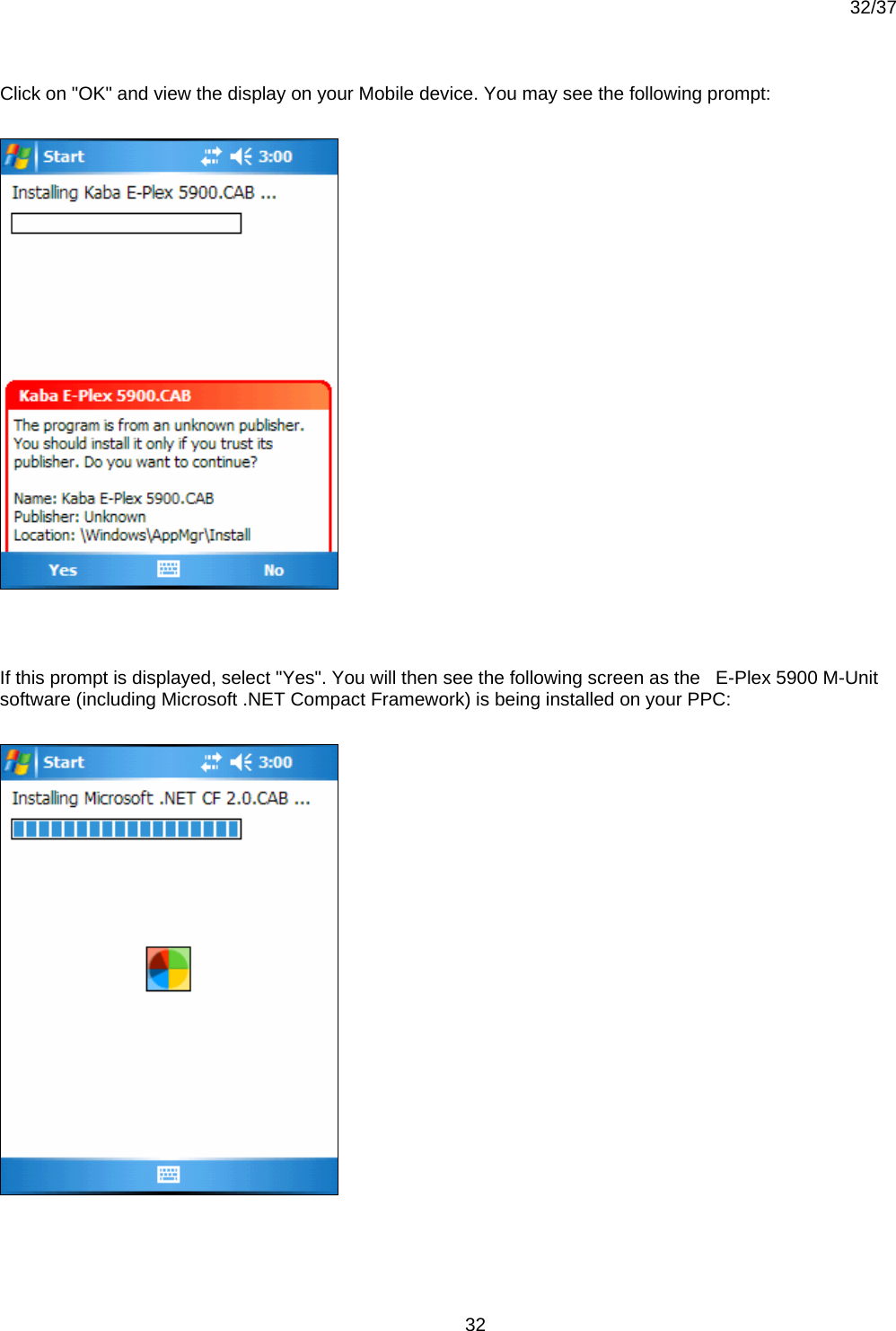
![26/37 26 Appendix Kaba E-Plex 5900 M-Unit Software Install Instructions for Windows Mobile 5.0 [Beta Version, June 2007] Prerequisites: • Windows Mobile (WM) 5.0 handheld device (Version 5.0 or greater), typically a Pocket PC (PPC) • Microsoft ActiveSync (Version 4.5 or greater) / Windows Mobile Device Center installed on your and running • Microsoft Windows XP / Vista Operating System Overview The “E-Plex 5900 M-Unit” (Maintenance Unit) application runs solely on the Windows Mobile platform. However, the software installation is made on both the host PC and the WM handheld device. Ensure that both PC and the PPC are connected before you start.](https://usermanual.wiki/Kaba-Ilco/58005900/User-Guide-842352-Page-26.png)