KROHNE FMCW10G52 Tank Level Probing Radar User Manual MA OPTIWAVE5200 en 160704 4001904903 R03
KROHNE, Inc Tank Level Probing Radar MA OPTIWAVE5200 en 160704 4001904903 R03
KROHNE >
Contents
- 1. User Manual
- 2. User Manual EN - JH5FMCW10G52.pdf
User Manual EN - JH5FMCW10G52.pdf
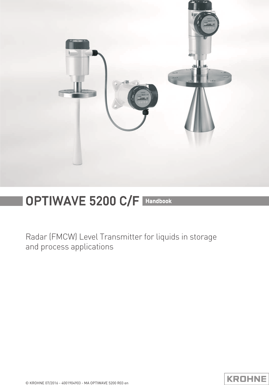

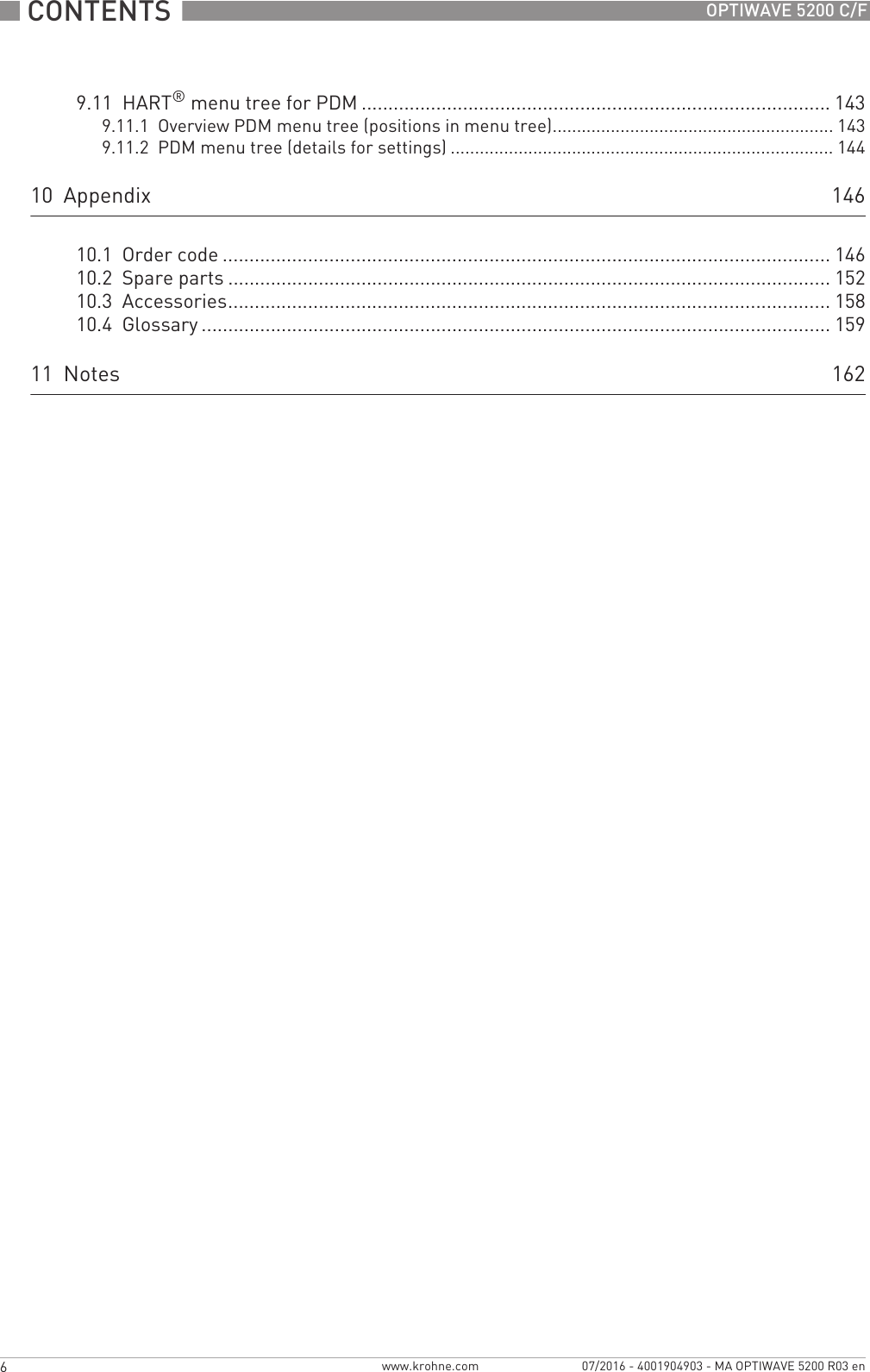
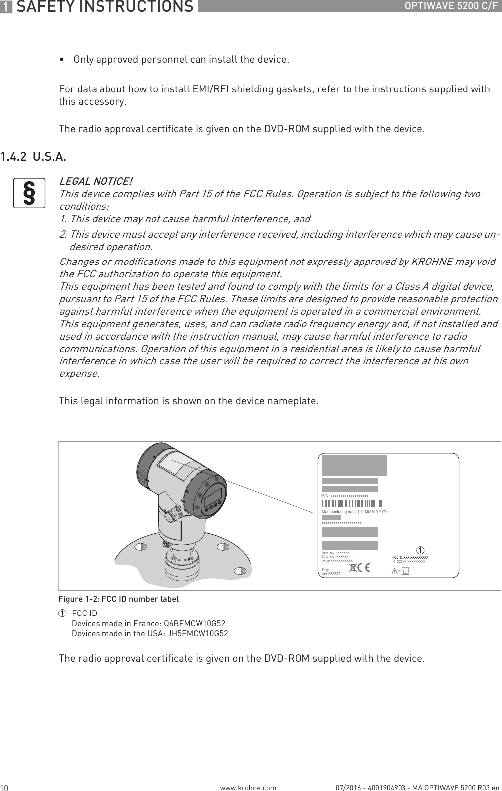
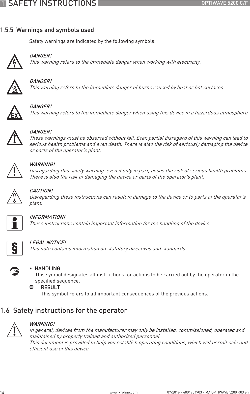
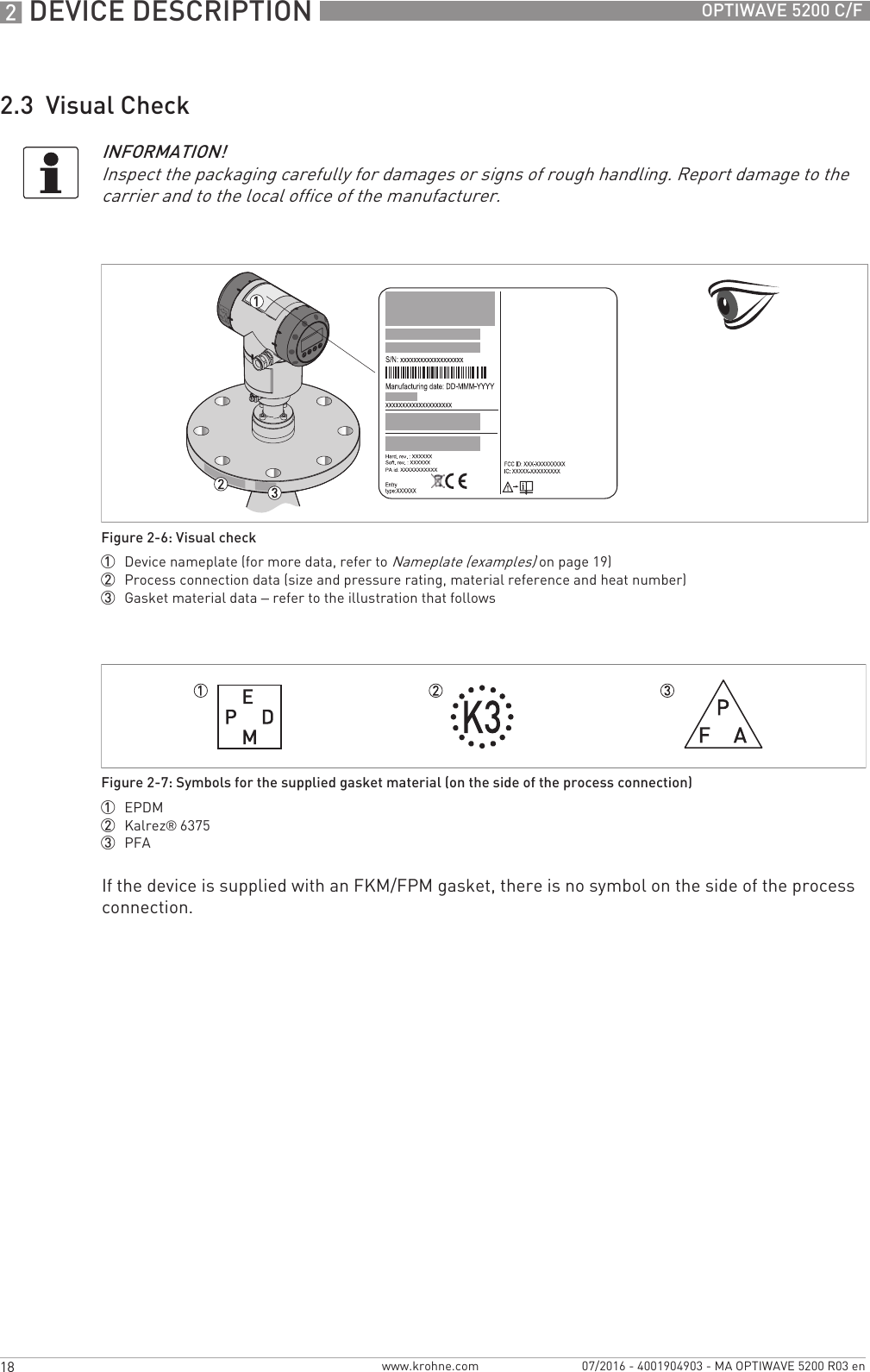
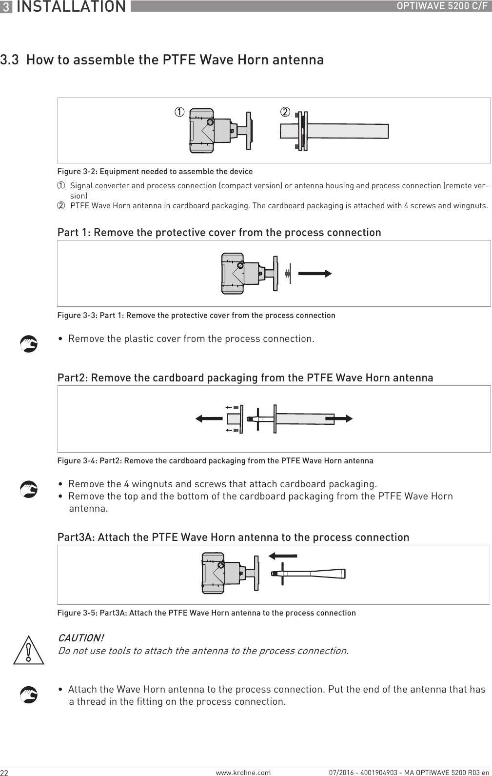
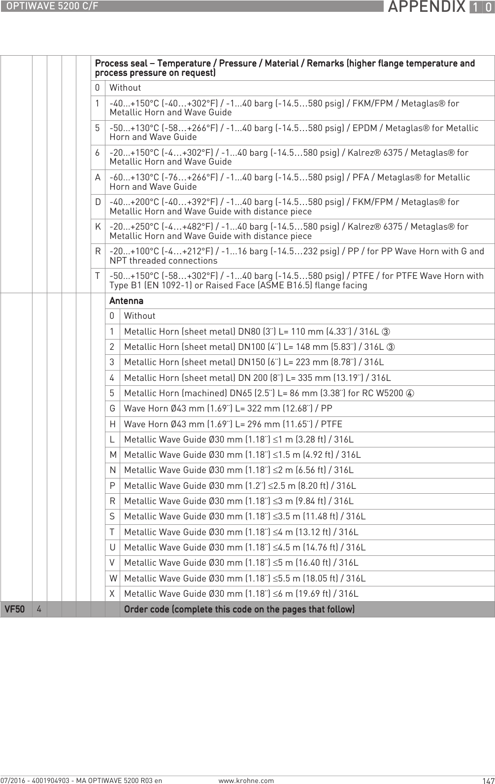
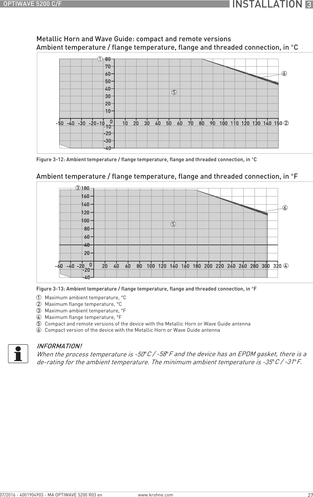
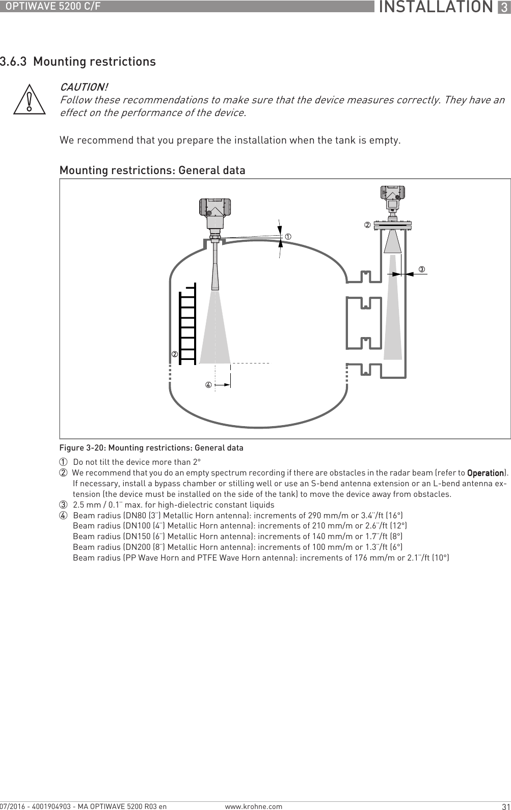
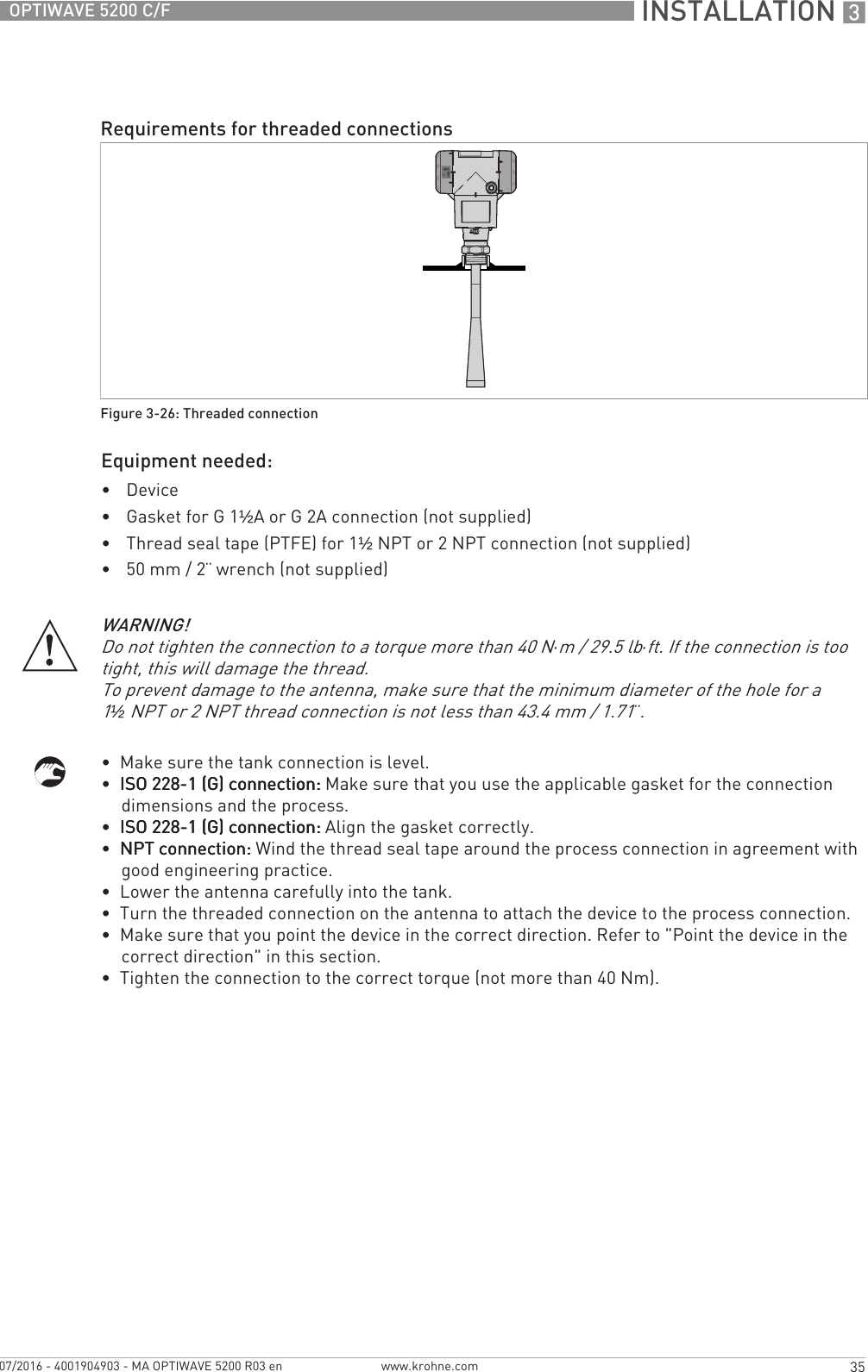
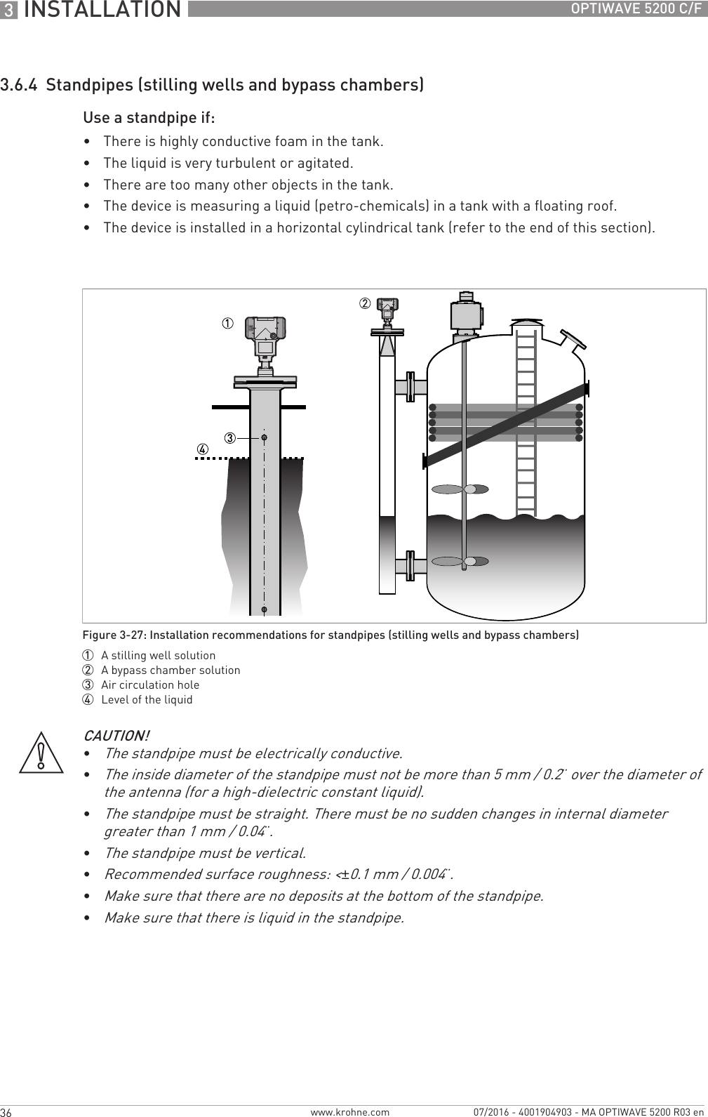
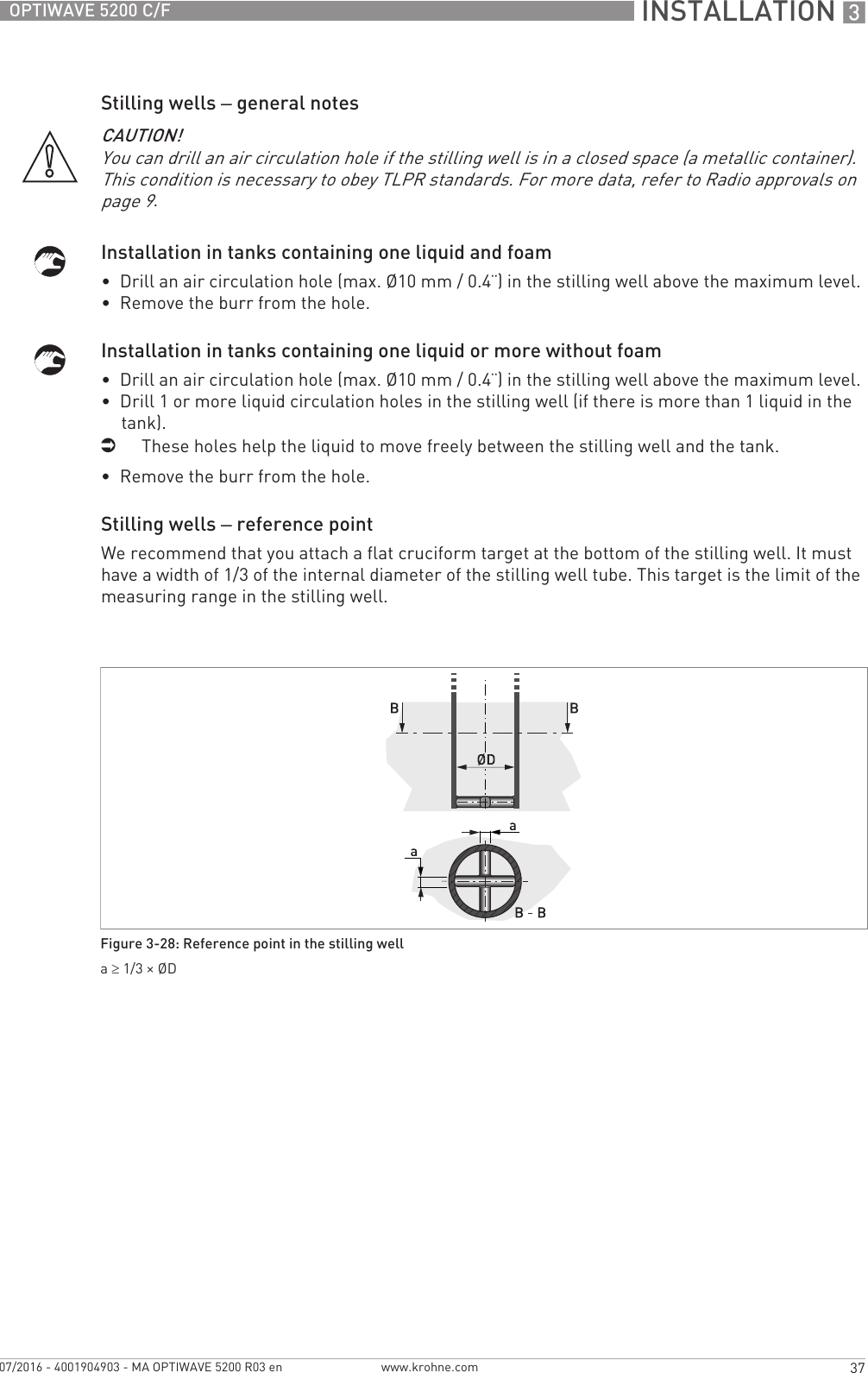
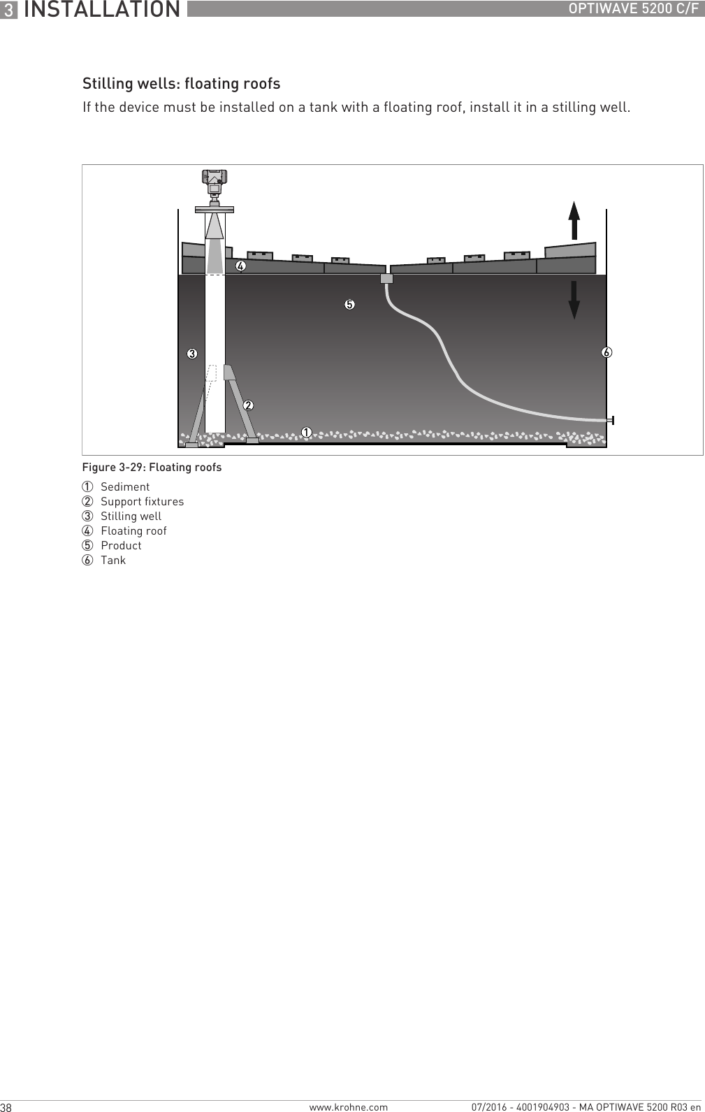
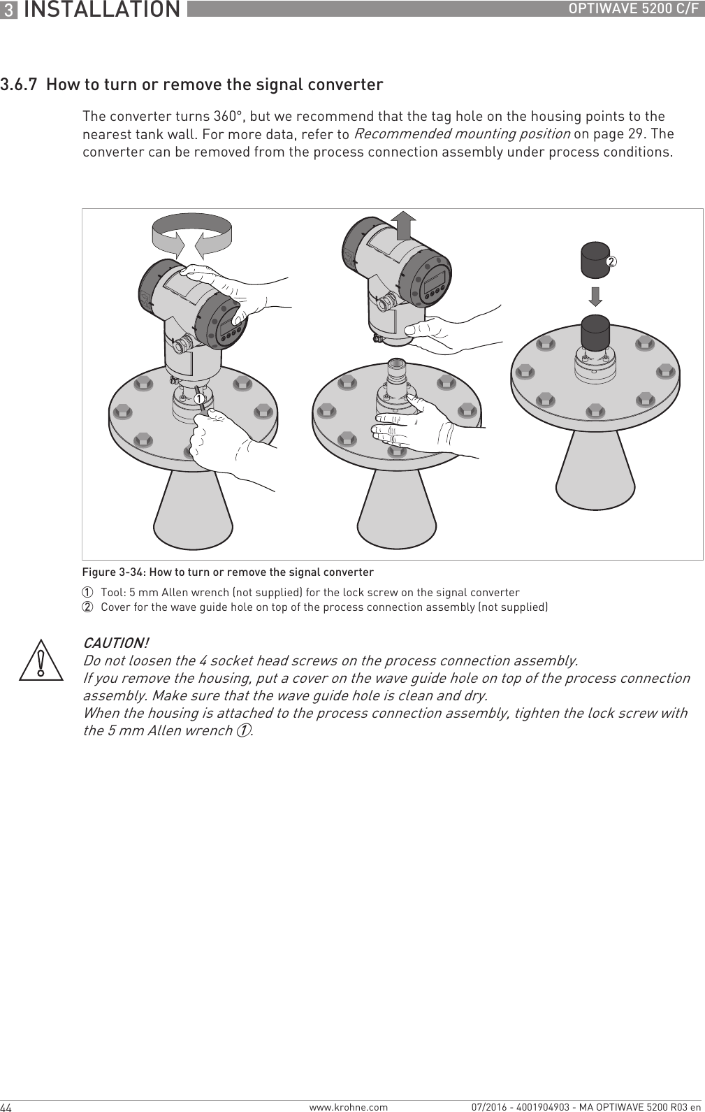
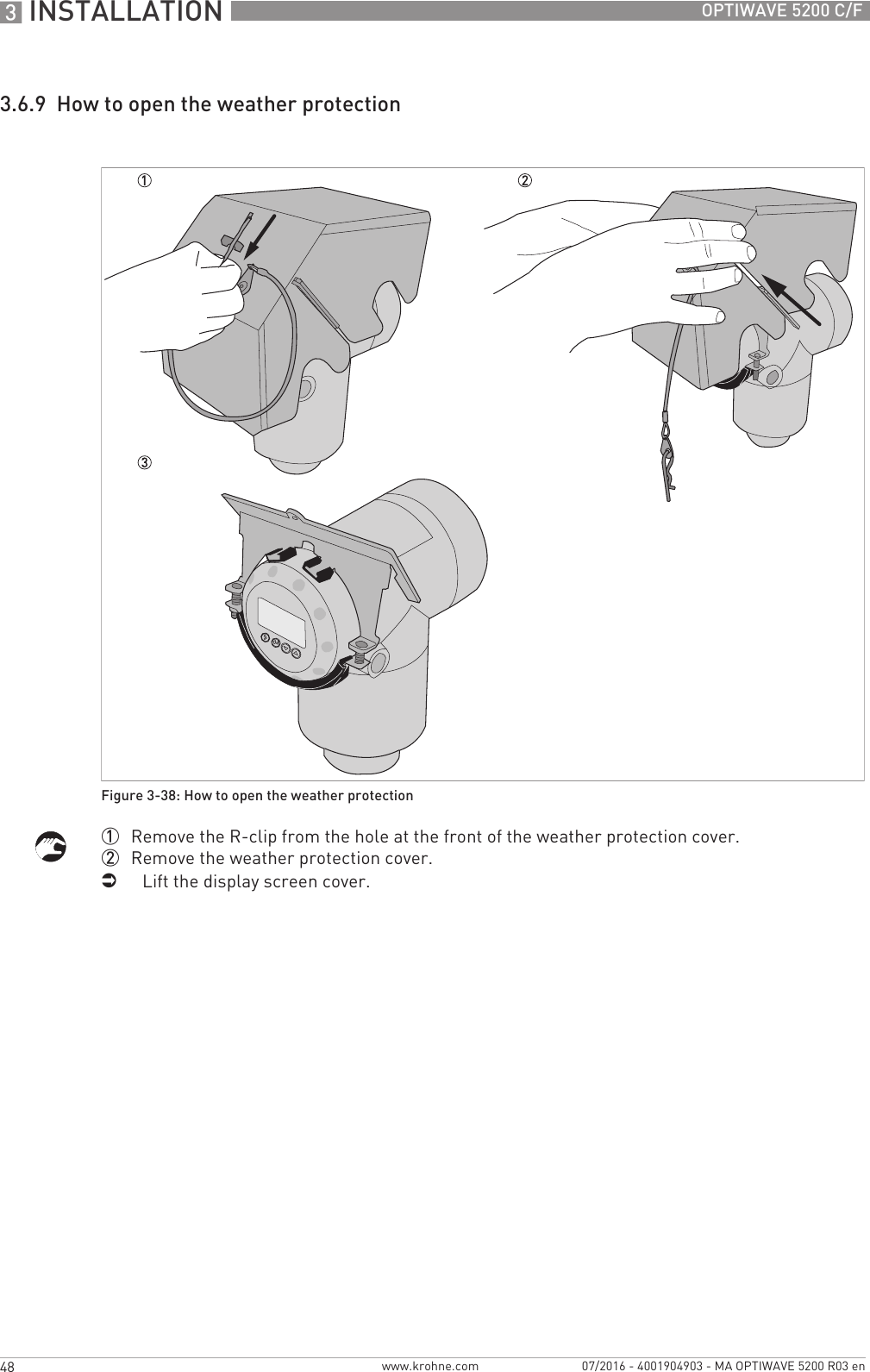
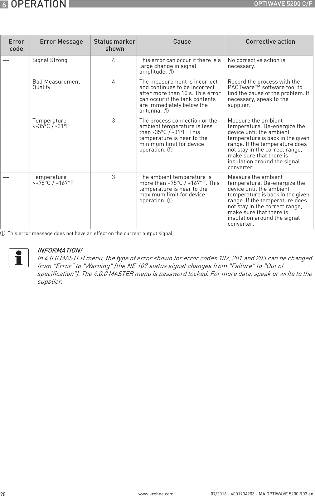
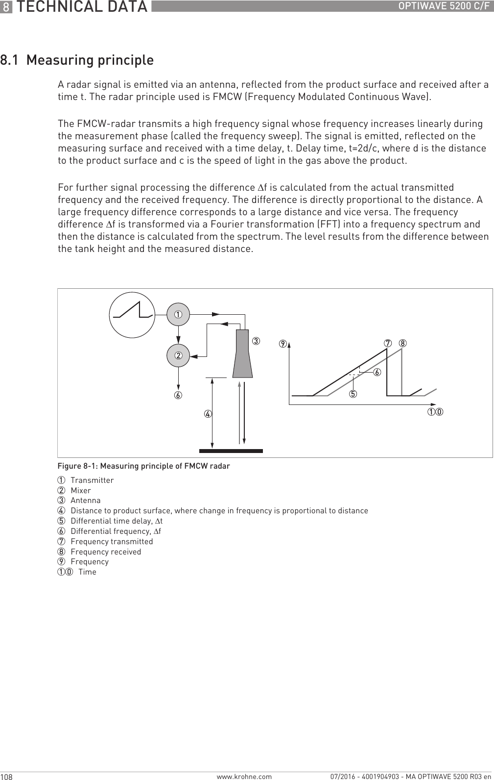
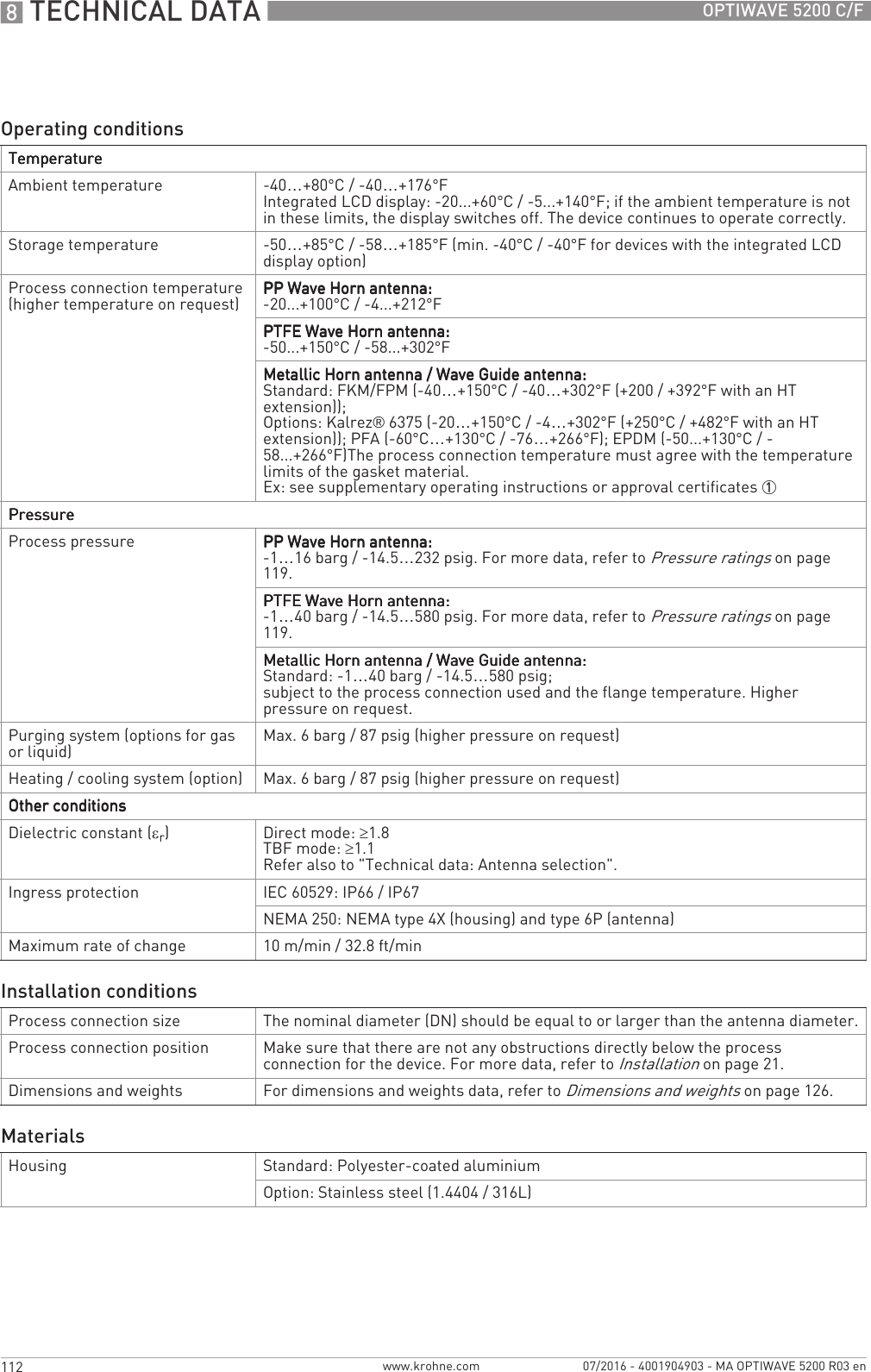
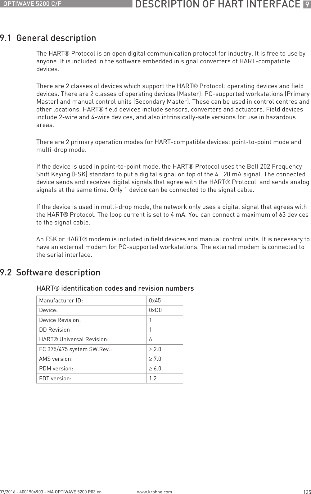
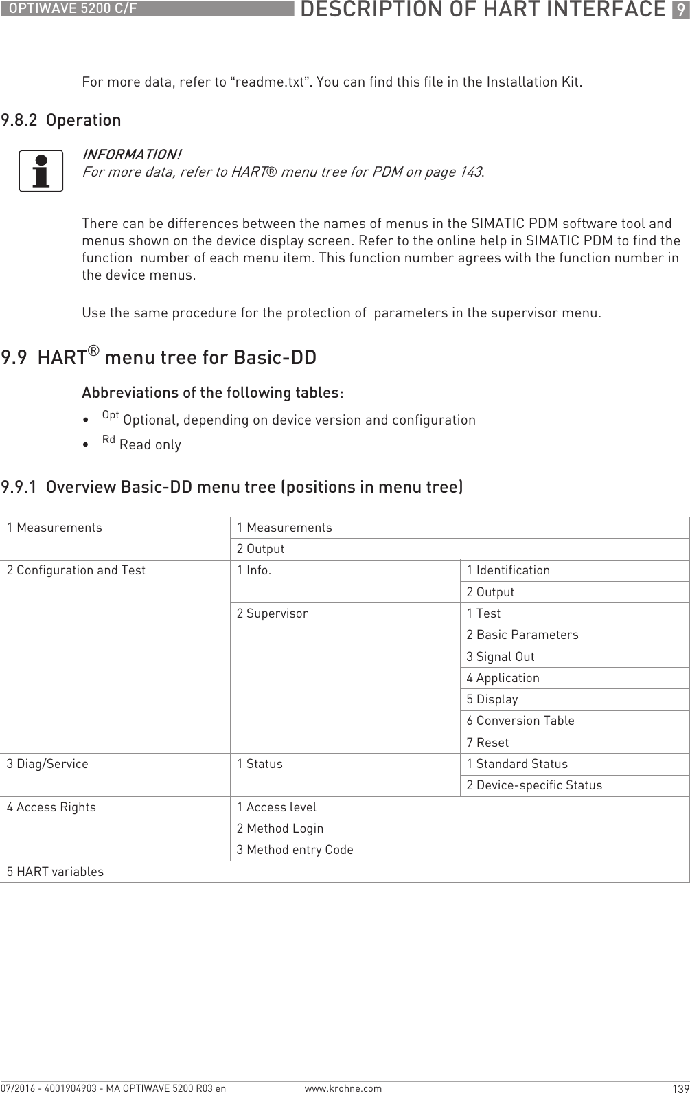
![3 INSTALLATION 24 OPTIWAVE 5200 C/Fwww.krohne.com 07/2016 - 4001904903 - MA OPTIWAVE 5200 R03 enFor more data on pressure ratings, refer to Pressure ratings on page 119Figure 3-7: Pressure and temperature ranges1 Temperature at the process connectionNon-Ex devices: The temperature range depends on the type of antenna, process connection and the seal material. Refer to the table that follows.Devices with Hazardous Location approvals: see supplementary instructions2 Ambient temperature for operation of the display-20...+60°C / -4...+140°FIf the ambient temperature is not between these limits, the display screen switches off automatically. The device con-tinues to operate.3 Ambient temperatureNon-Ex devices: refer to the ambient temperature / flange temperature graphs in this sectionDevices with Hazardous Location approvals: see supplementary instructions4 Process pressureDepends on the type of antenna and process connection. Refer to the table that follows.WARNING!The process connection temperature range must agree with the temperature limits of the gasket material.Antenna type Process connectionSeal Process connection temperatureProcess pressure[°C] [°F] [barg] [psig]PP Wave Horn G1½...2;1½...2 NPT —-20...+100 -4...+212 -1...16 -14.5...232PTFE Wave Horn Flange with PTFE plate—-50...+150 -58...+302 -1...40 -14.5...580Metallic HornWave GuideFlange Metaglas® with FKM/FPM-40...+200 1-40...+392 1-1...40 2-14.5...580 2Metaglas® with Kalrez® 6375-20...+250 1-4...+482 1-1...40 2-14.5...580 2Metaglas® with PFA-60...+130 1-76...+266 1-1...40 2-14.5...580 2Metaglas® with EPDM-50...+130 1-58...+266 1-1...40 2-14.5...580 21Higher temperature on request2Higher pressure on request](https://usermanual.wiki/KROHNE/FMCW10G52.User-Manual-EN-JH5FMCW10G52-pdf/User-Guide-4017651-Page-24.png)
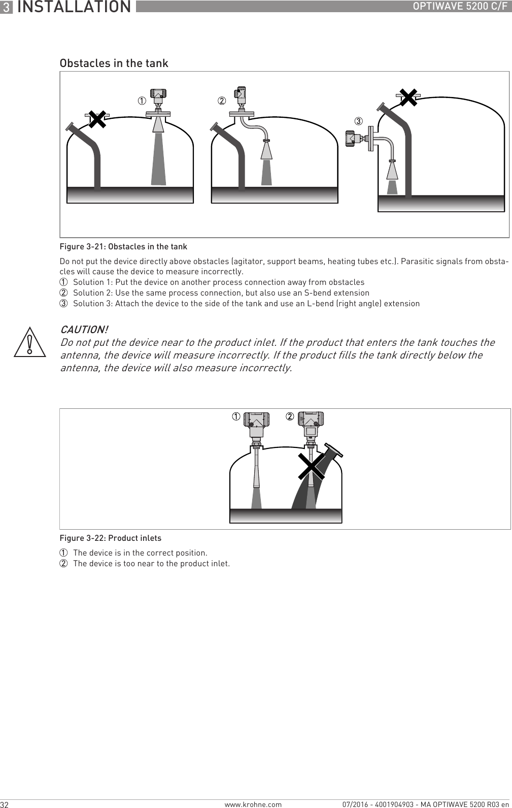
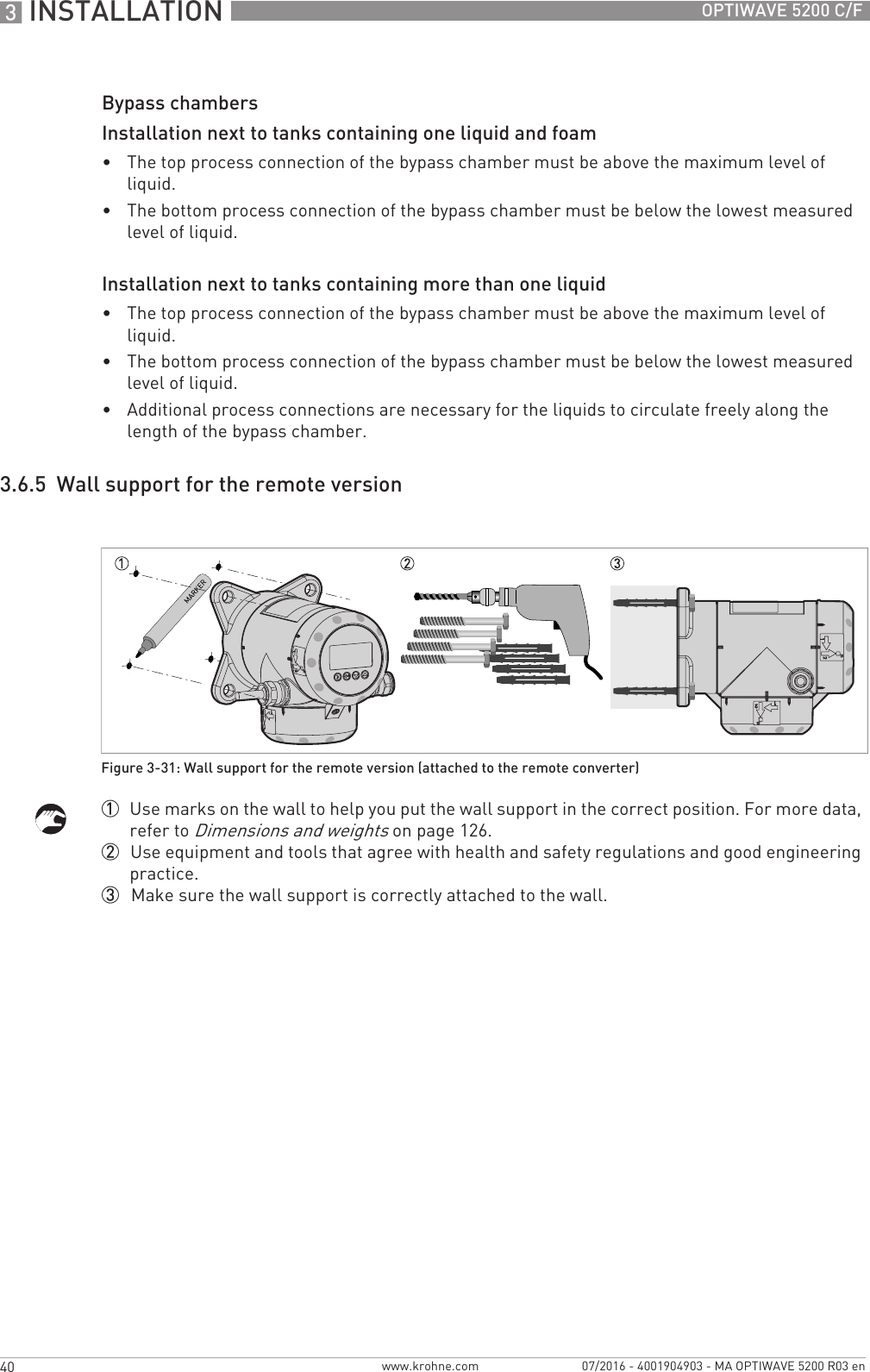
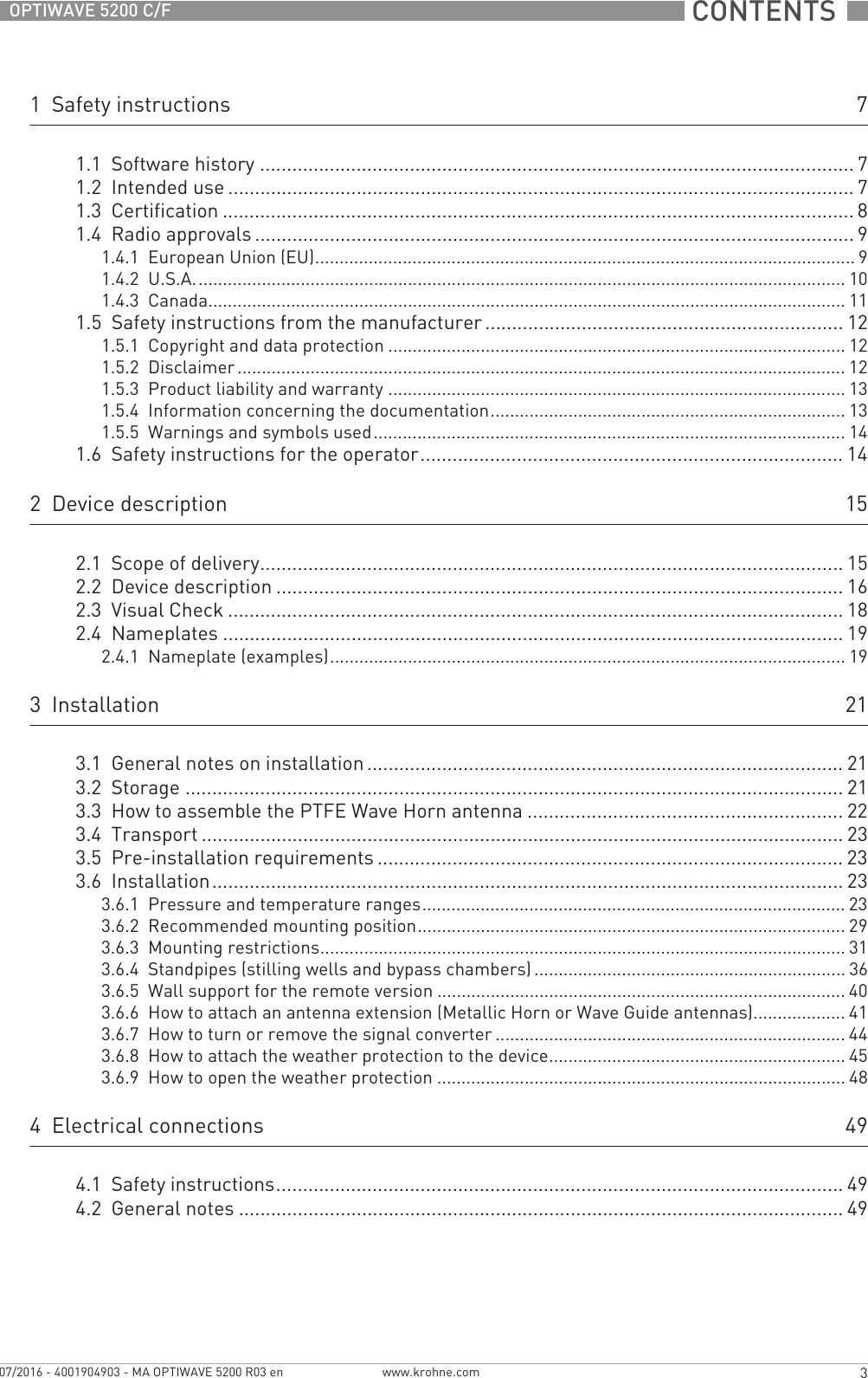
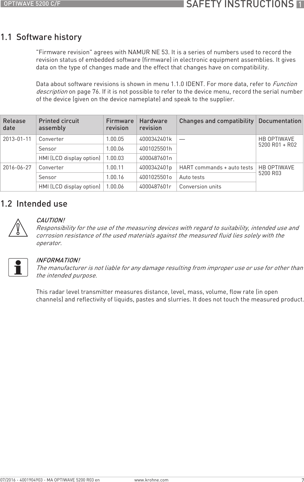
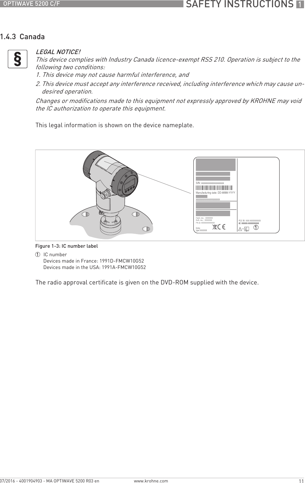
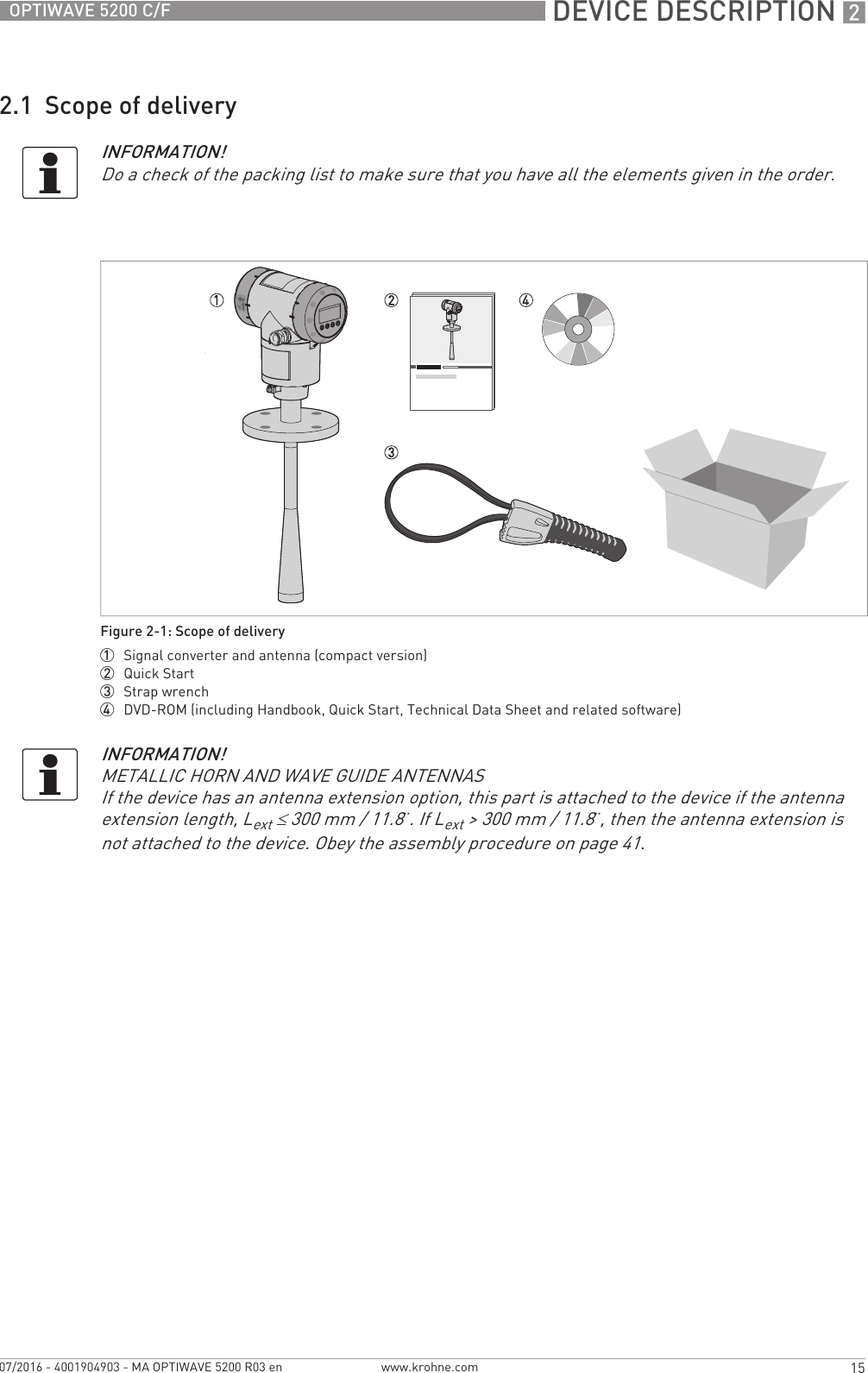
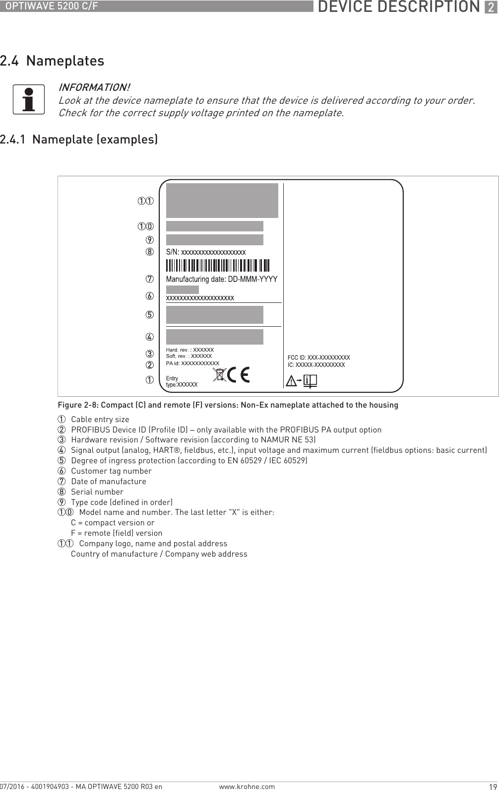
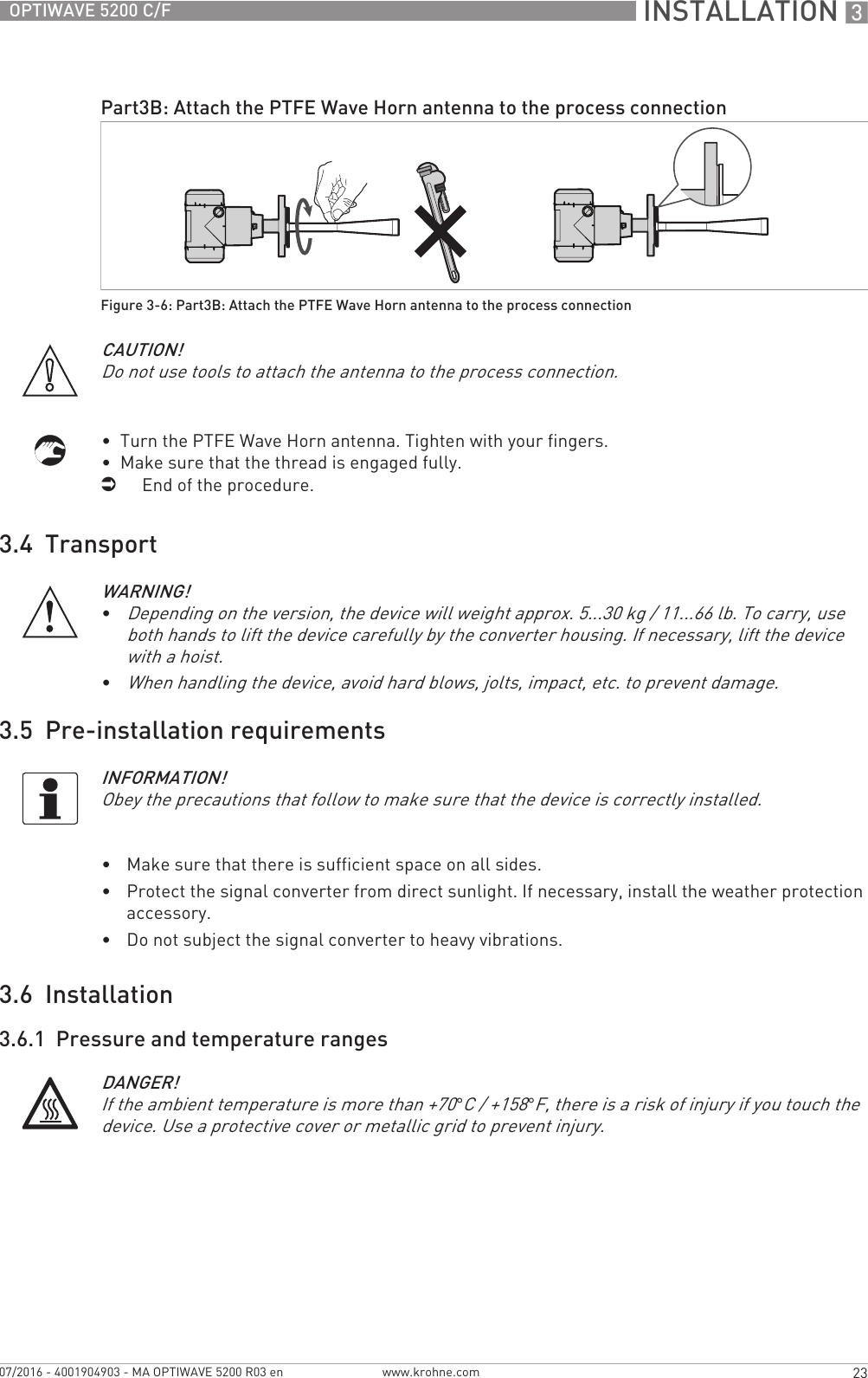
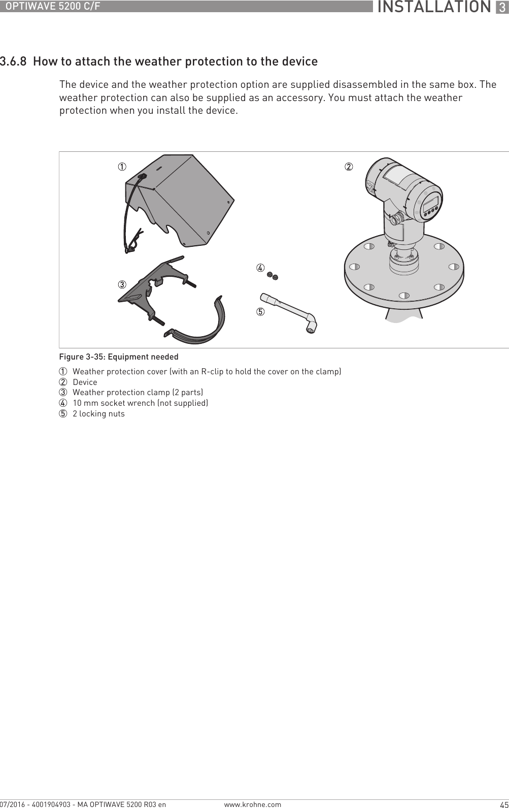
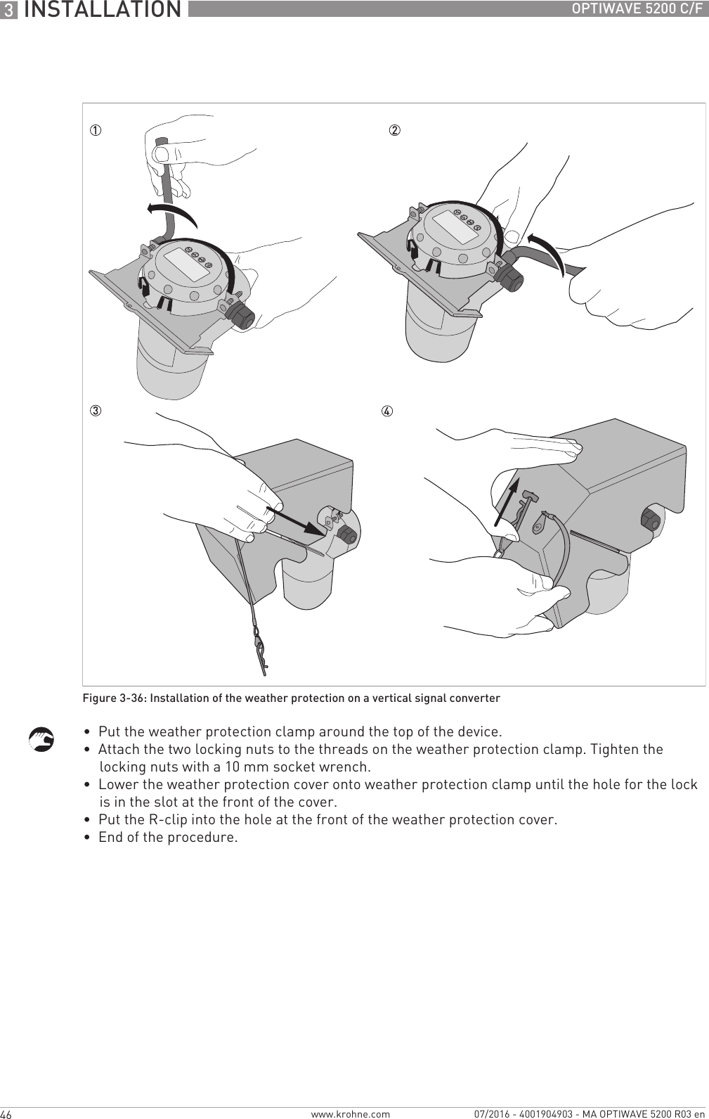
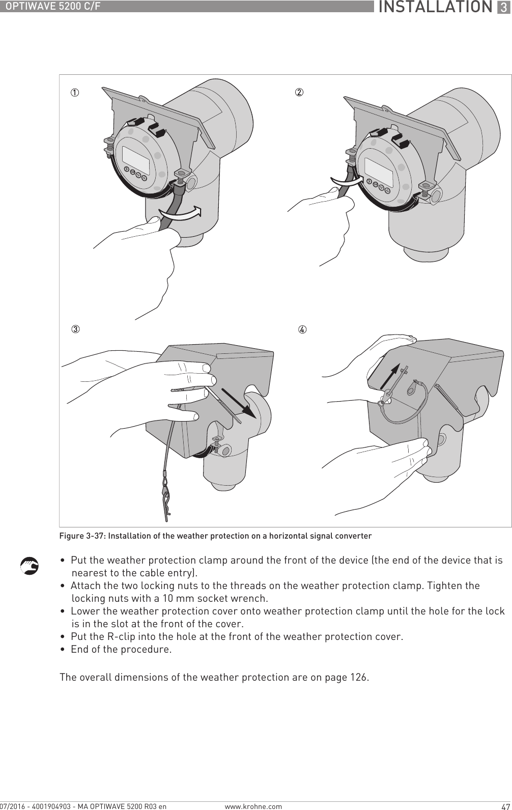
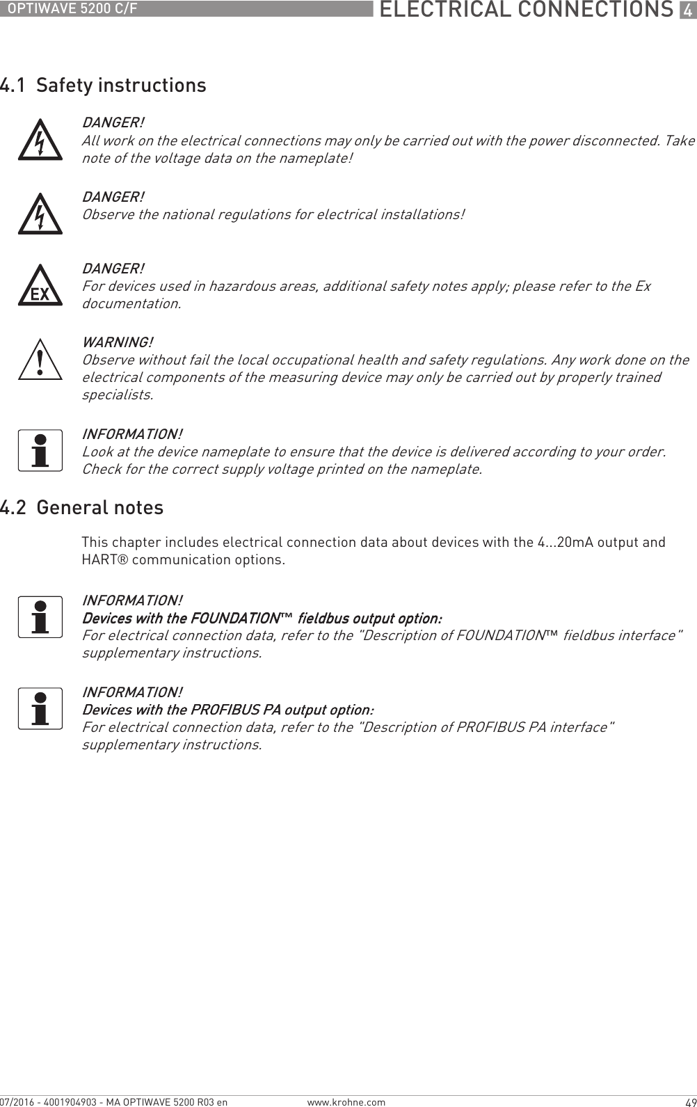
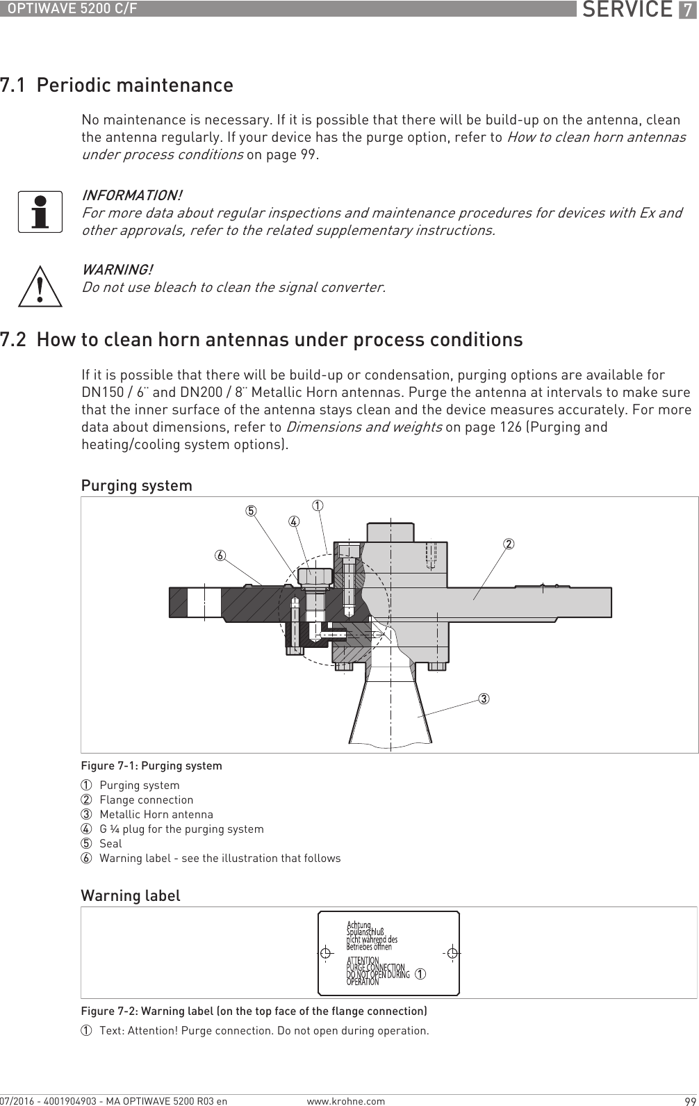
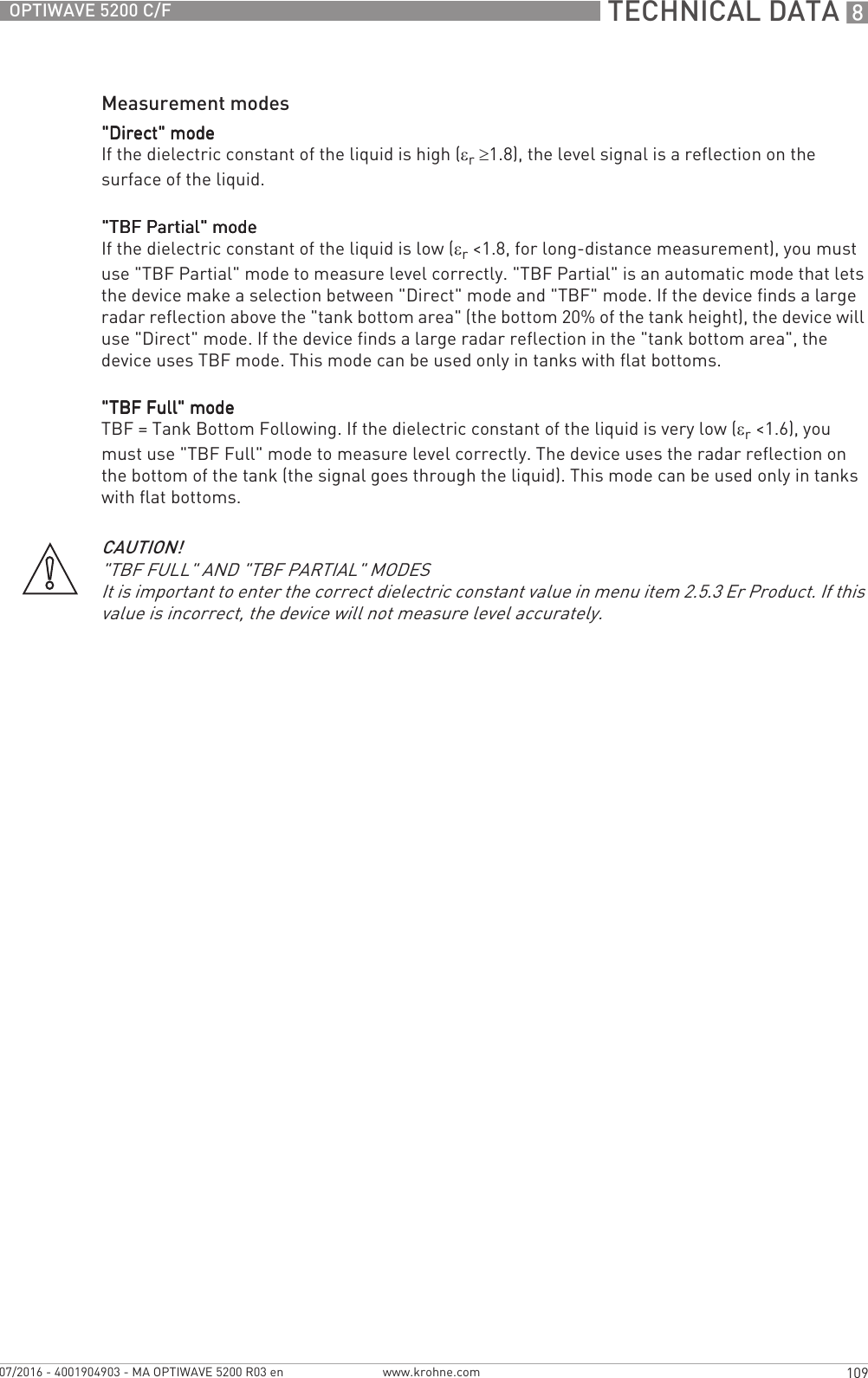
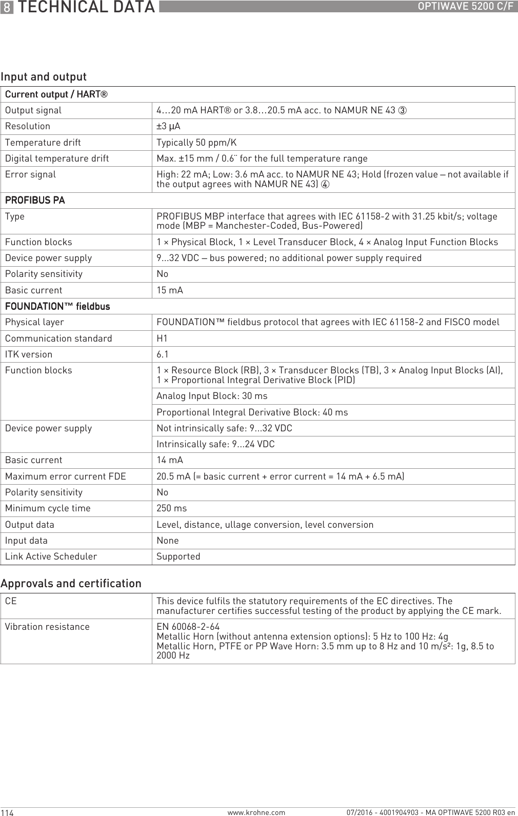
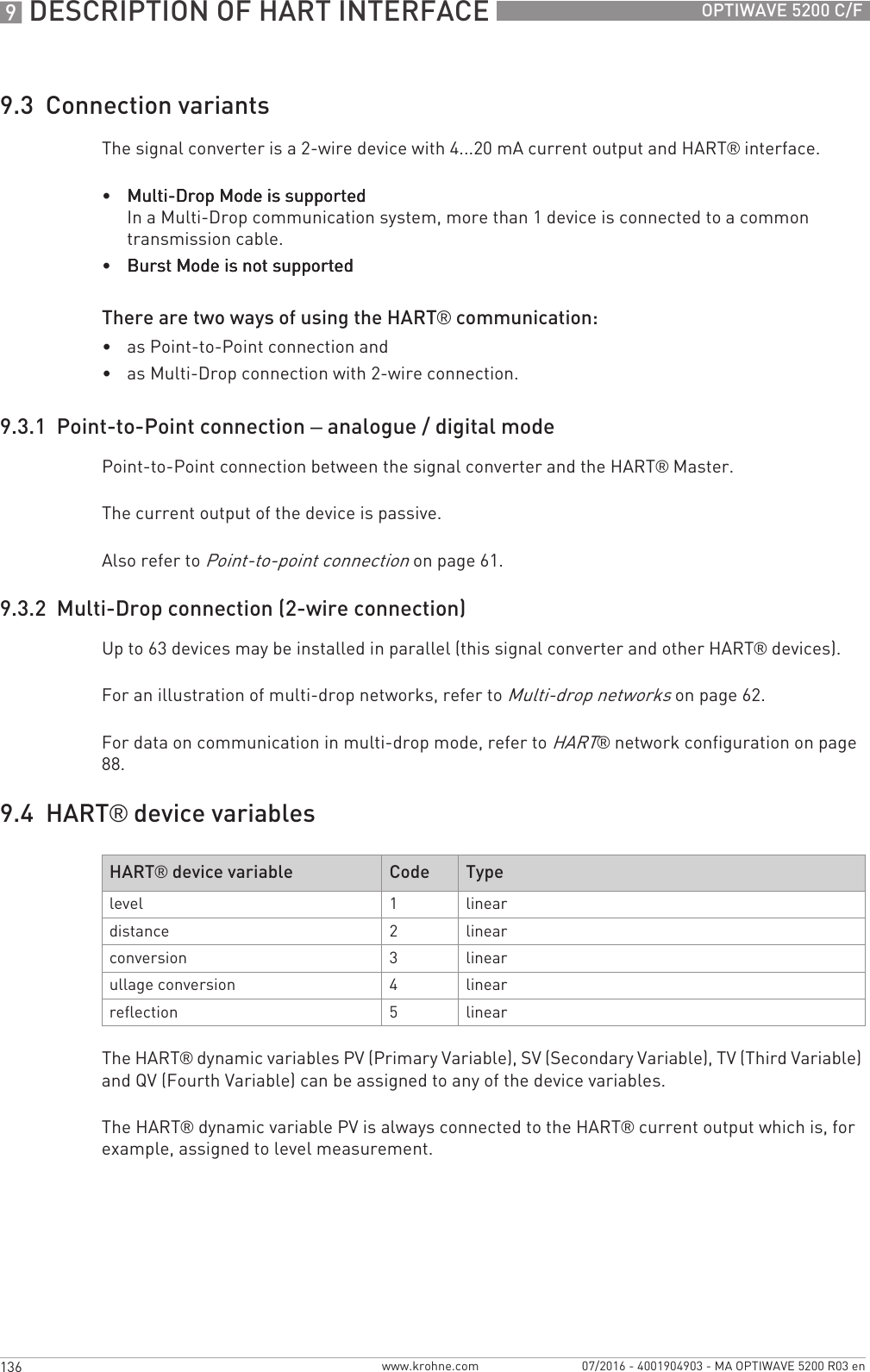
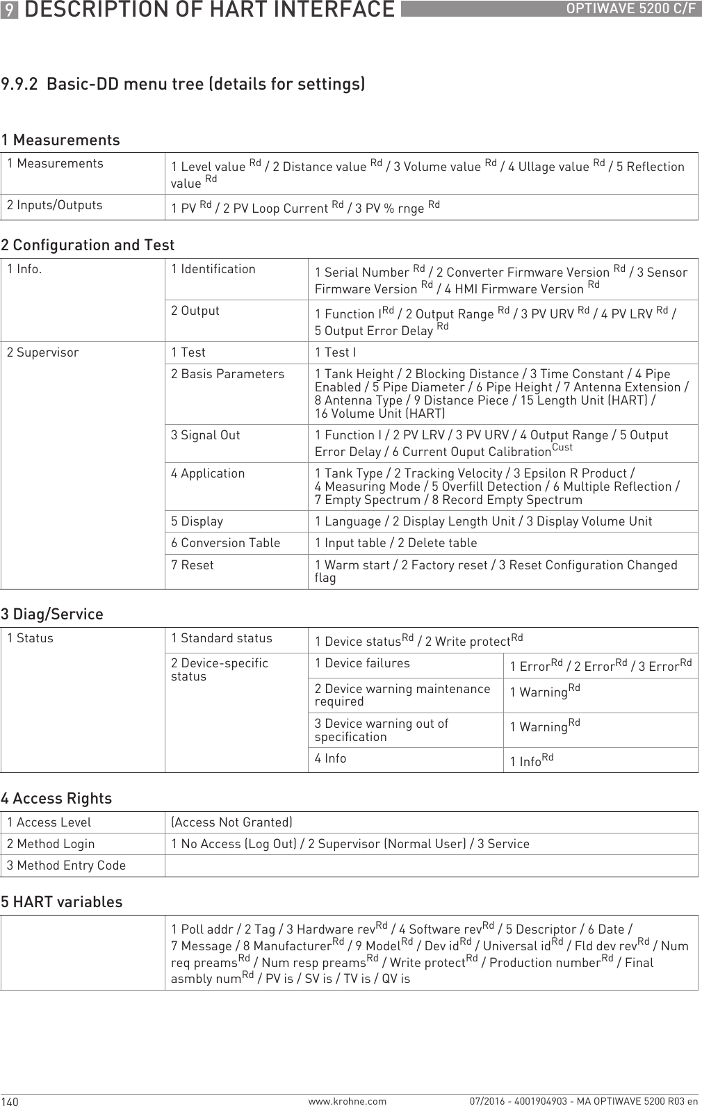
![INSTALLATION 343OPTIWAVE 5200 C/Fwww.krohne.com07/2016 - 4001904903 - MA OPTIWAVE 5200 R03 enantenna extension, S-bend antenna extension or L-bend (right angle) antenna extension.Procedure 2A: Device settings for a device with a straight antenna extension• Enter the SUPERVISOR menu (2.0.0).• Push [>>>>], 2 × [], [>>>>] and 6 × [] to go to menu item ANTENNA EXTENSION (2.3.7).• Push [>>>>] to change the value. Push [>>>>] to change the position of the cursor. Push [] to decrease the value or [] to increase the value.iIf the antenna extension has a length of 500 mm, enter the value "500" (if units for this menu item are in mm).• Push 3 × [^^^^] to go back to the "STORE" screen.• Push [] or [] to set the screen to STORE YESSTORE YESSTORE YESSTORE YES and push [^^^^].iEnd of the procedure.Procedure 2B: Device settings for a device with an S-bend or L-bend (right angle) antenna extension• Enter the SUPERVISOR menu (2.0.0).• Push [>>>>], 2 × [], [>>>>] and 6 × [] to go to menu item ANTENNA EXTENSION (2.3.7).• Push [>>>>] to change the value. Push [>>>>] to change the position of the cursor. Push [] to decrease the value or [] to increase the value.iIf units are in mm, enter the value "221" (for an S-bend extension) or "236" (for an L-bend extension).• Push [^^^^] to go back to the menu. Push 2 × [] to go to menu item DIST.PIECE (2.3.9).• Push [>>>>] to change the value. Push [>>>>] to change the position of the cursor. Push [] to decrease the value or [] to increase the value.iIf units are in mm, enter the value "243" (for an S-bend extension) or "236" (for an L-bend extension).• Push 3 × [^^^^] to go back to the "STORE" screen.• Push [] or [] to set the screen to STORE YESSTORE YESSTORE YESSTORE YES and push [^^^^].iEnd of the procedure.Settings for devices with antenna extensions in mmFor more data about the dimensions of devices with antenna extensionsFor more data about the dimensions of devices with antenna extensions, refer to Dimensions and weights on page 126.Antenna extension type Device settingsANTENNA EXTENSION (2.3.7) DIST.PIECE (2.3.9)Straight 10 2S-bend 221 243 2L-bend (right angle) 236 236 21This value depends on the length of the antenna extension. Enter the length of the antenna extension: 100, 200, 300, 400, 500 or 1000 mm2If the device has a high temperature extension, add 120 mm to this value](https://usermanual.wiki/KROHNE/FMCW10G52.User-Manual-EN-JH5FMCW10G52-pdf/User-Guide-4017651-Page-43.png)
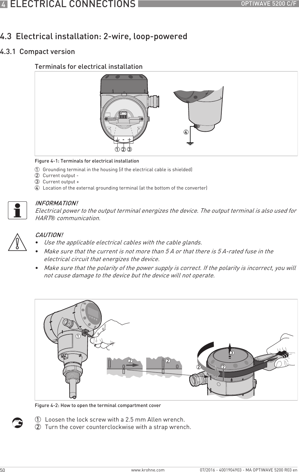
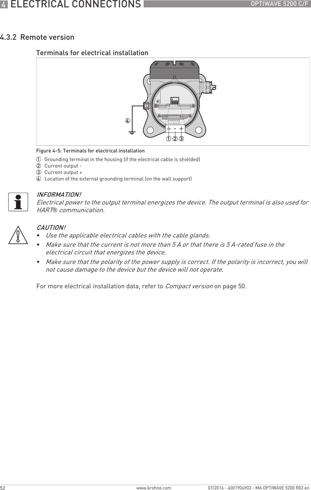
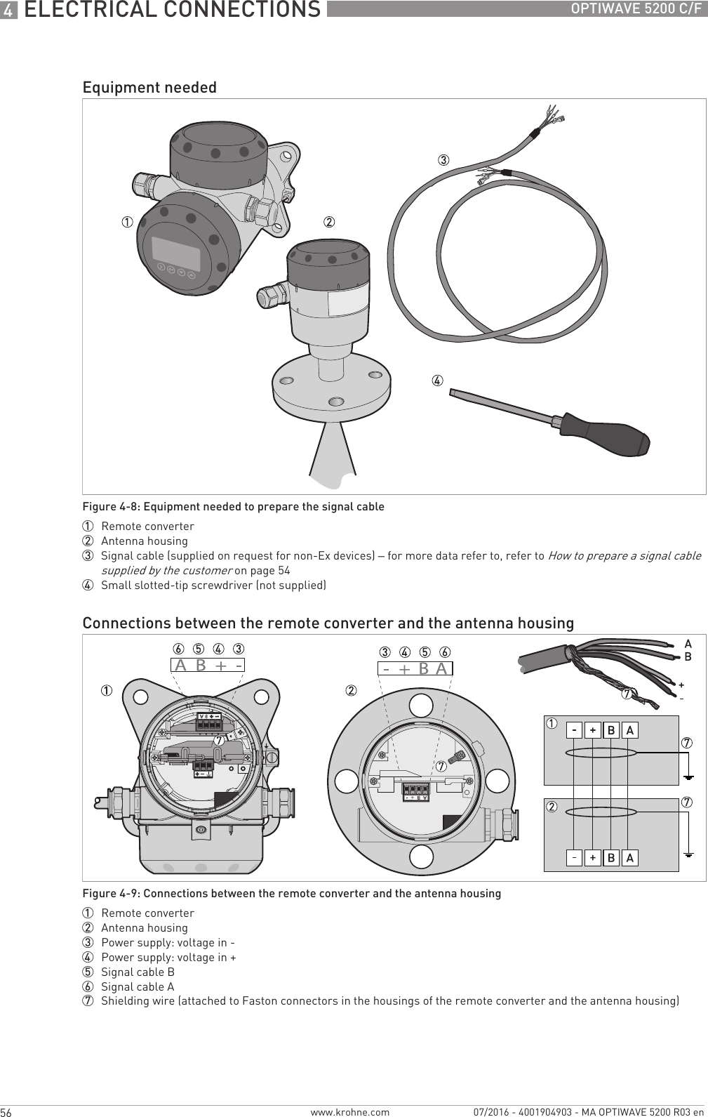
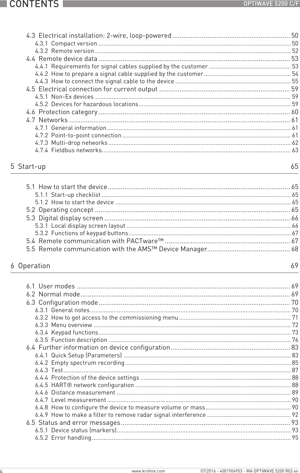
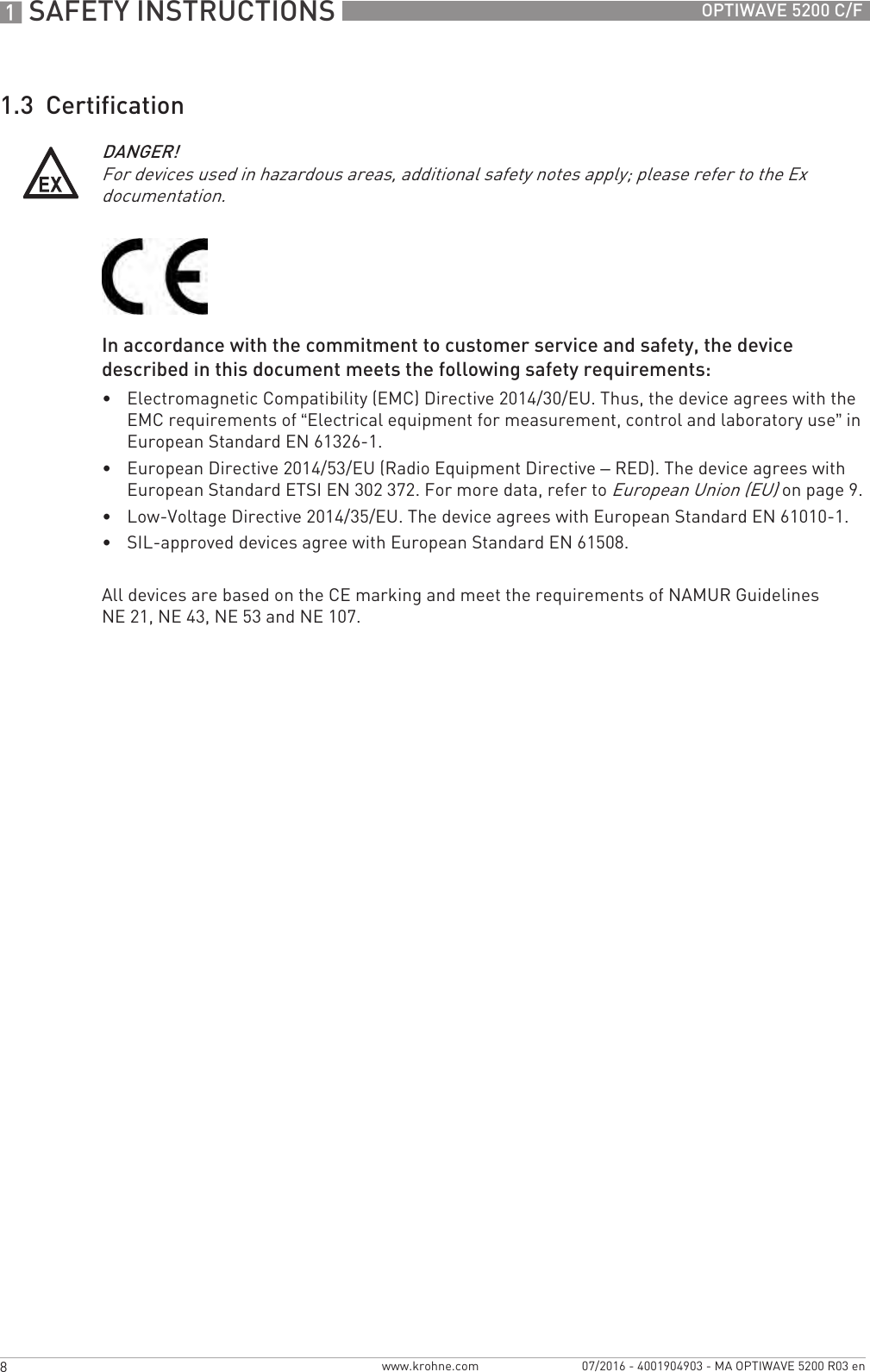
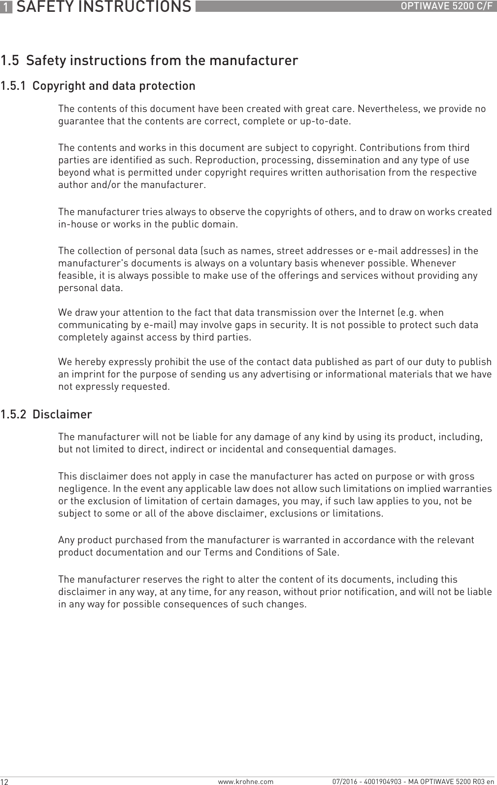
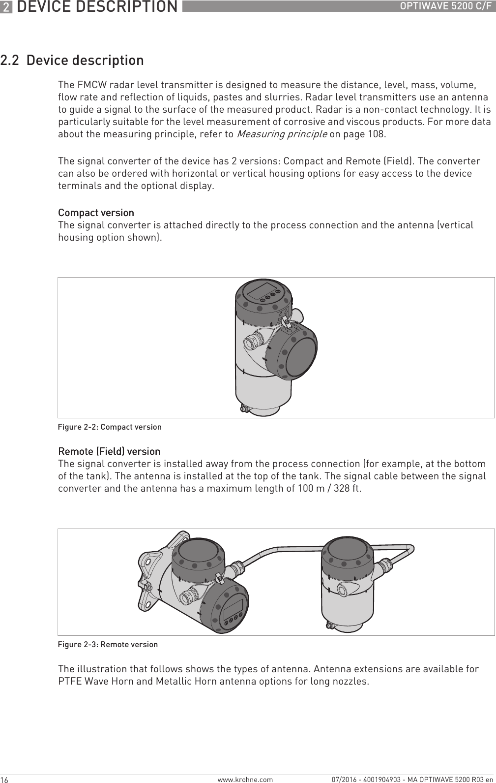
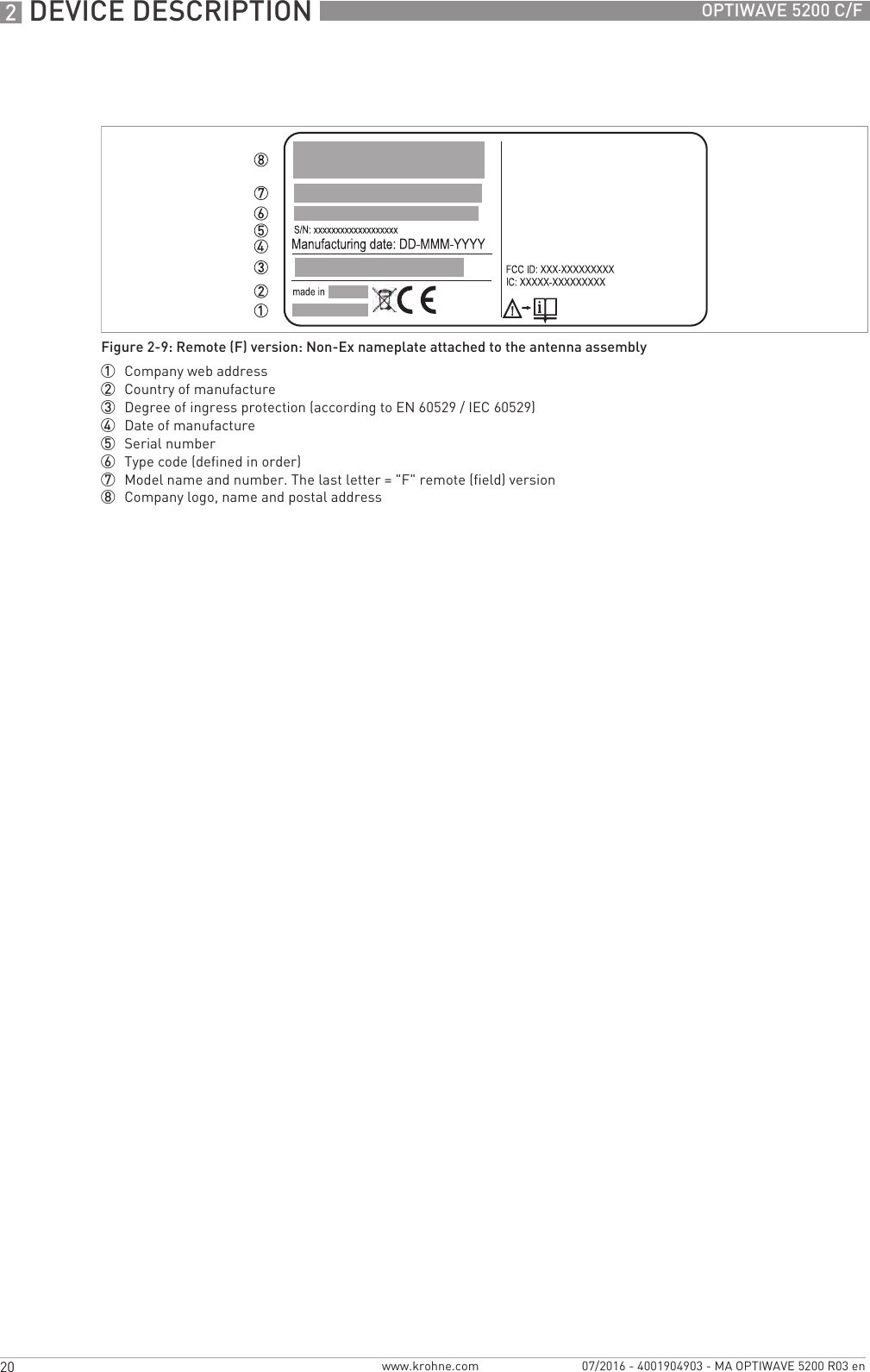
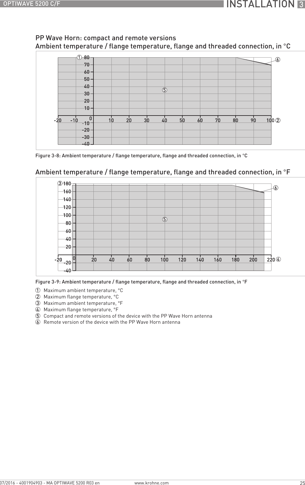
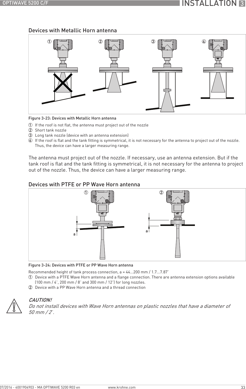
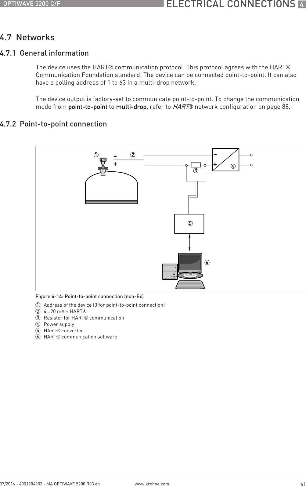
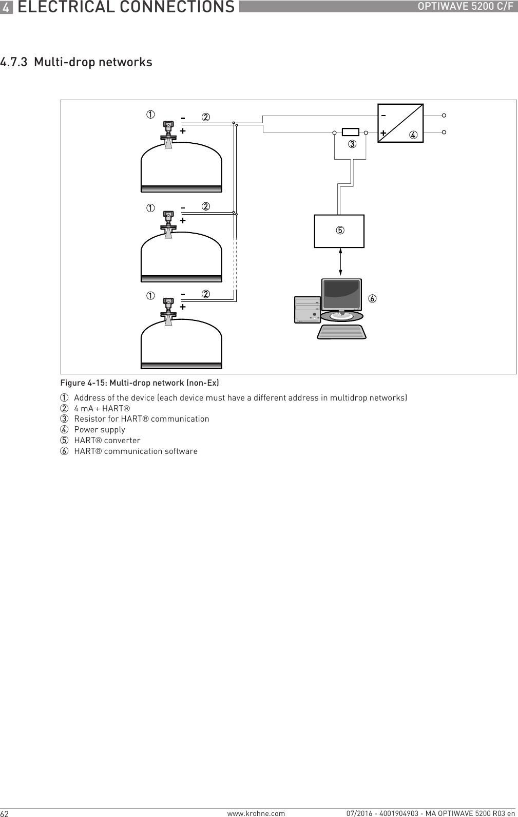
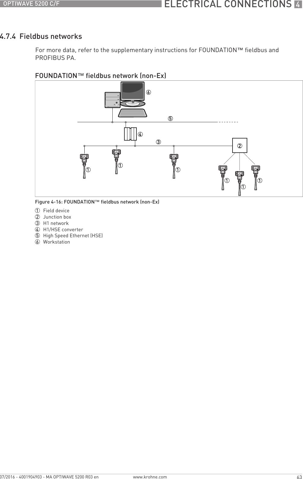
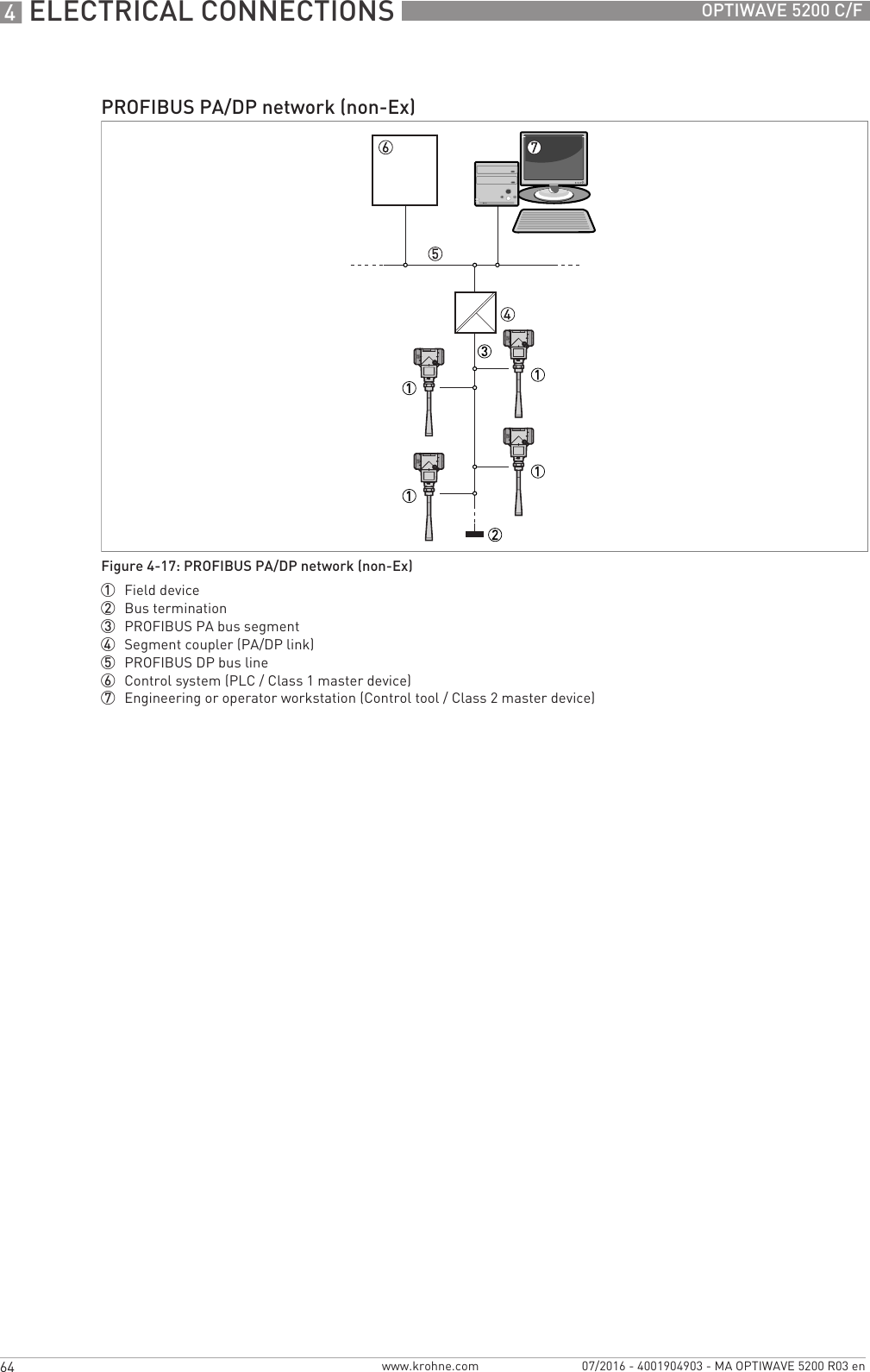
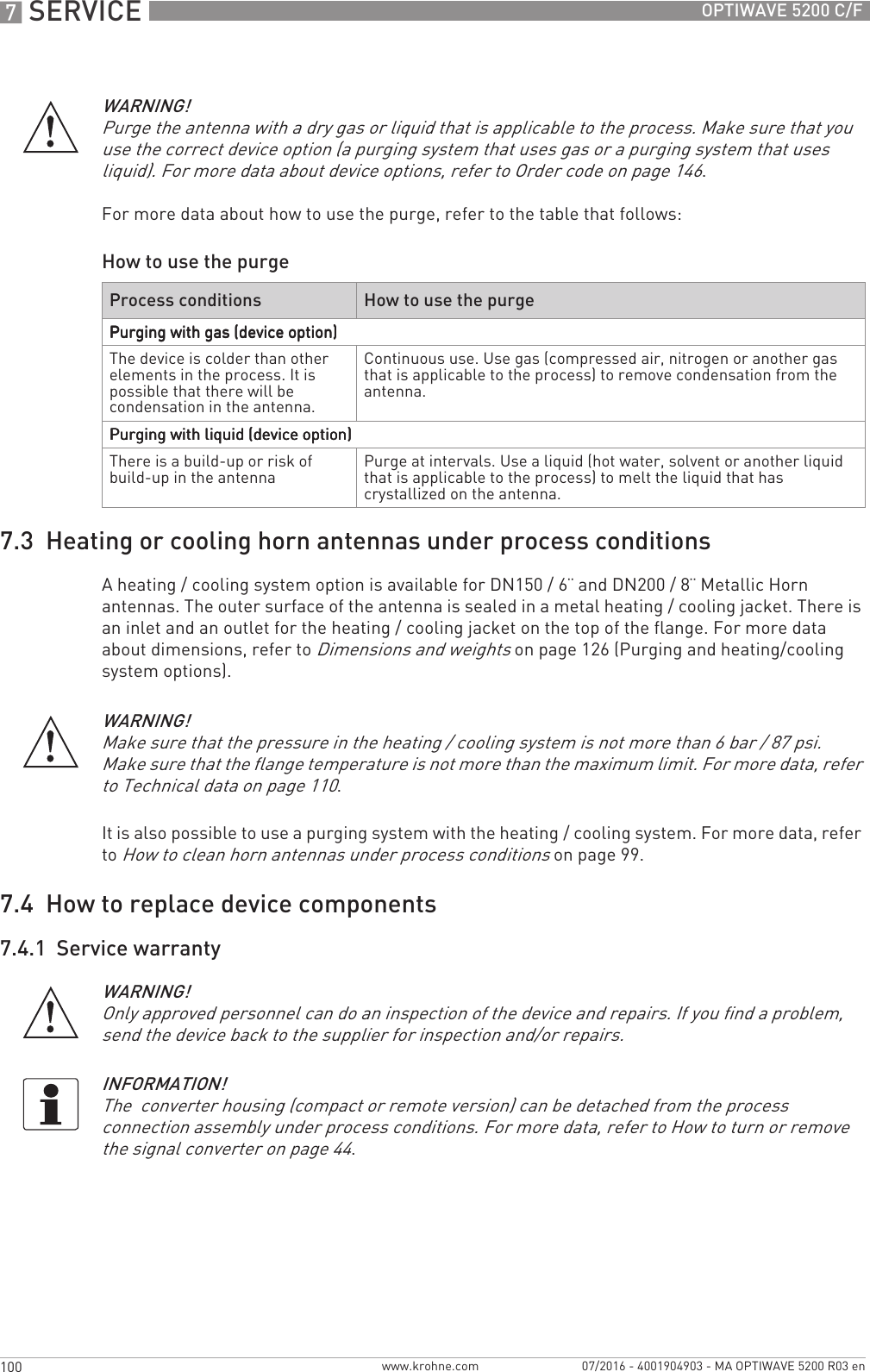
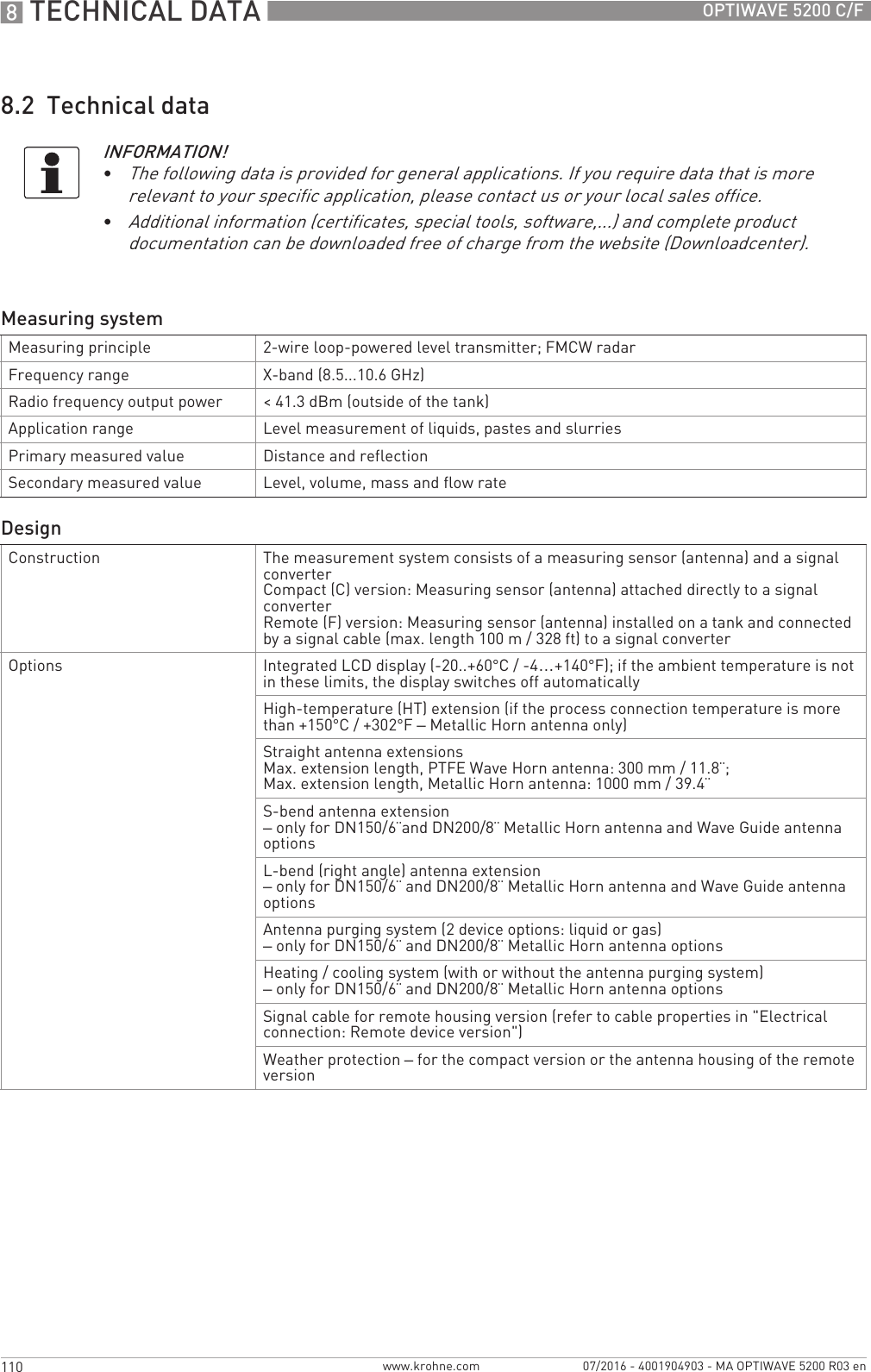
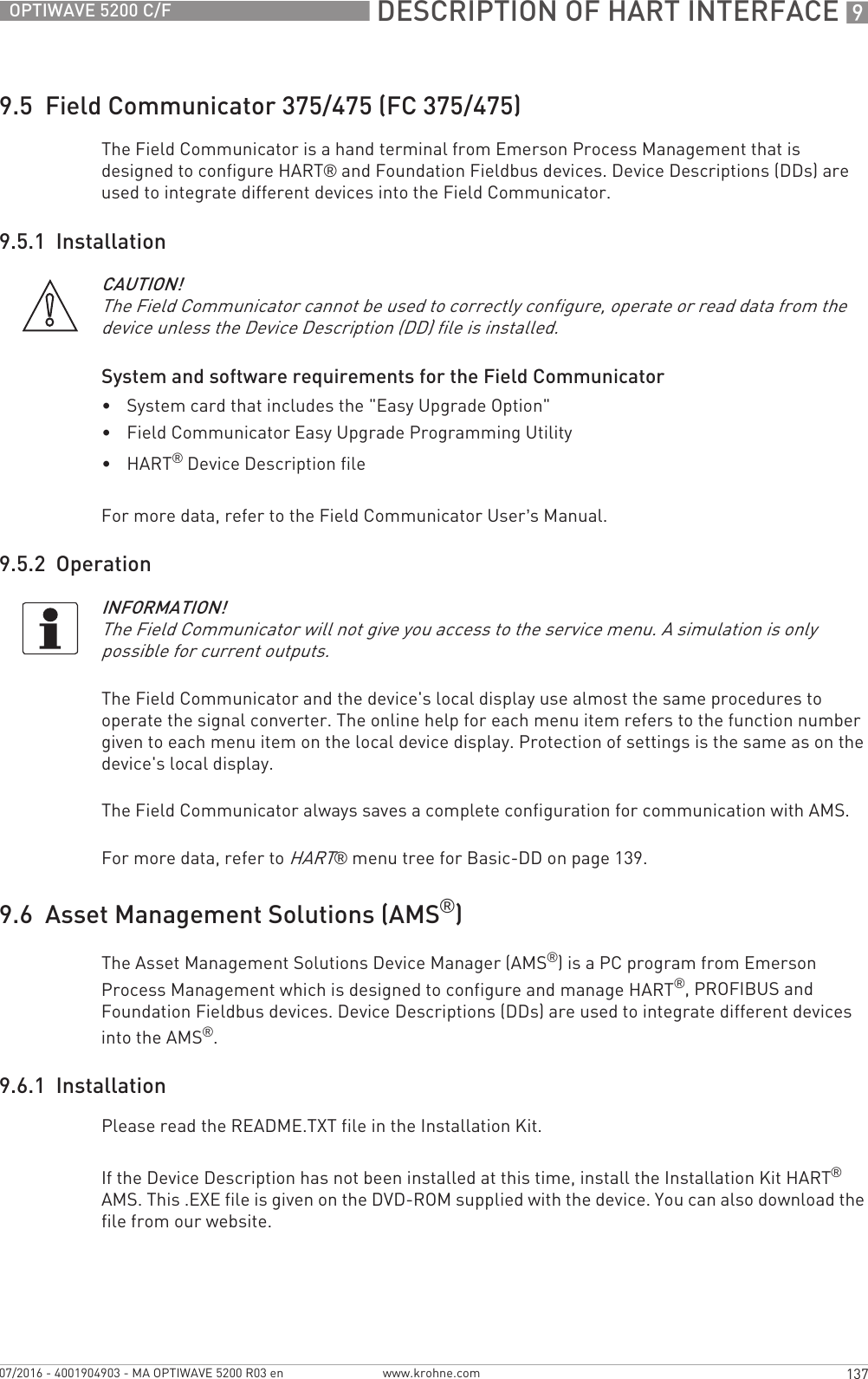
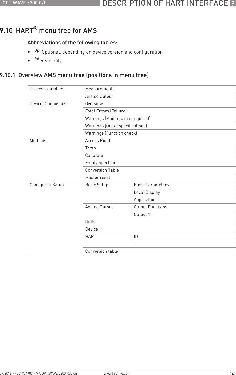
![4 ELECTRICAL CONNECTIONS 60 OPTIWAVE 5200 C/Fwww.krohne.com 07/2016 - 4001904903 - MA OPTIWAVE 5200 R03 en4.6 Protection category• Make sure that the gaskets are not damaged.• Make sure that the electrical cables are not damaged.• Make sure that the electrical cables agree with the national electrical code.• The cables are in a loop in front of the device 1 so water does not go into the housing.• Tighten the cable feedthroughs 2.• Close unused cable feedthroughs with dummy plugs 3.Refer to the table that follows for the diameter of the outer sheath of the electrical cable:Min. / Max. diameter of the electrical cableINFORMATION!The device fulfils all requirements per protection category IP66 / IP67. It also fulfils all requirements per NEMA type 4X (housing) and type 6P (antenna).DANGER!Make sure that the cable gland is watertight.Figure 4-13: How to make the installation agree with protection category IP67Type of electrical cable Approval Min. / Max. diameter of the electrical cable[mm] [inches]Power supply / output non-Ex / Ex i 6...7.5 0.24...0.3Power supply / output Exd 6...10 0.24...0.39Signal cable (for the remote version) 1non-Ex / Ex i / Ex d 6...10 0.24...0.391This electrical cable is connected between the remote converter and the antenna housing](https://usermanual.wiki/KROHNE/FMCW10G52.User-Manual-EN-JH5FMCW10G52-pdf/User-Guide-4017651-Page-60.png)
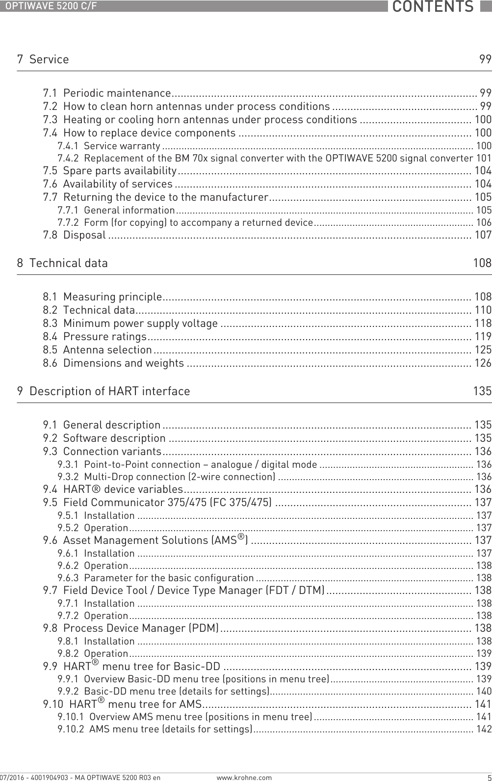
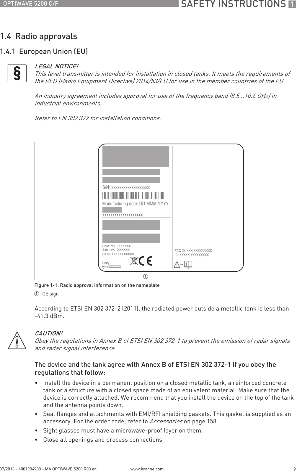
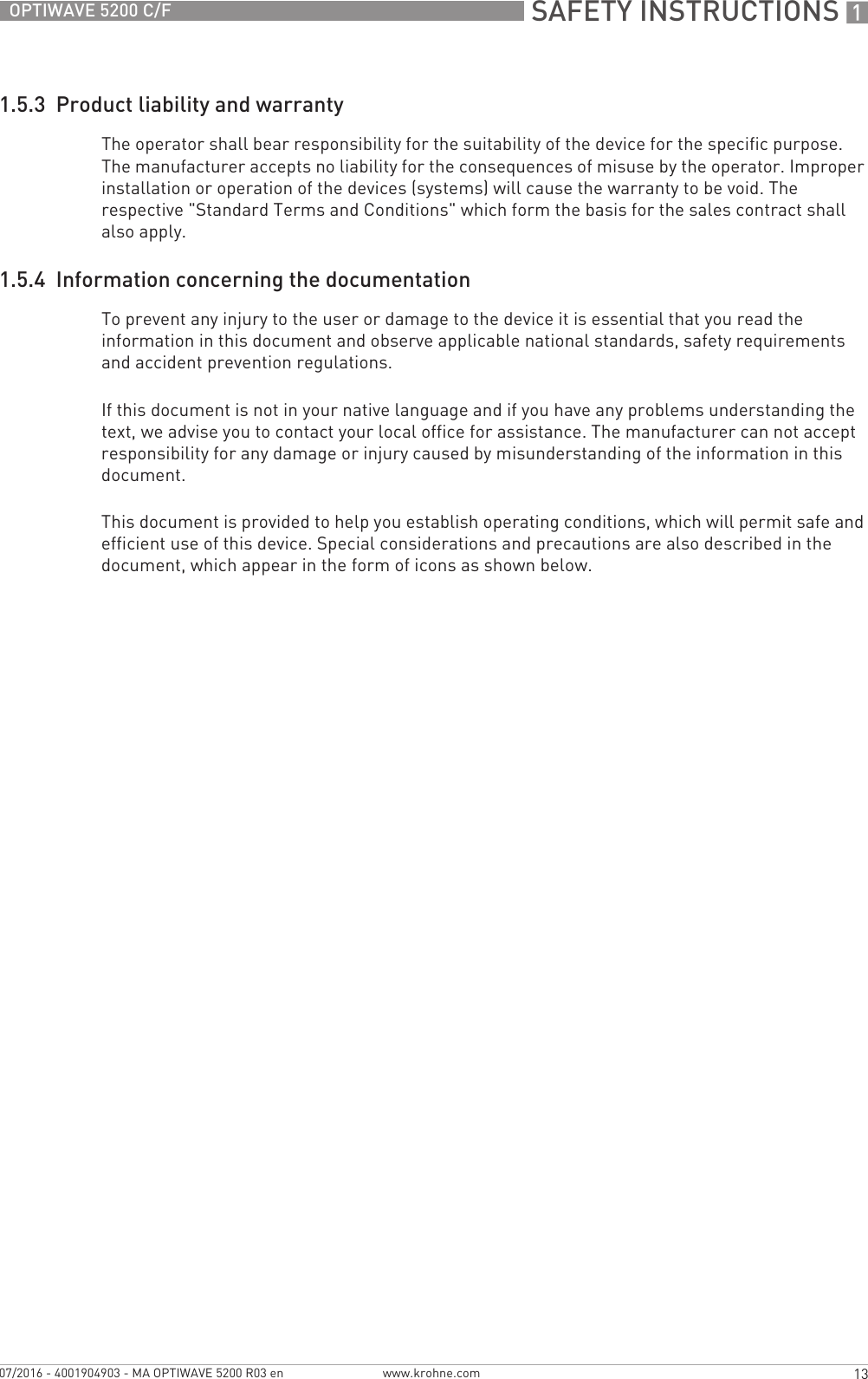
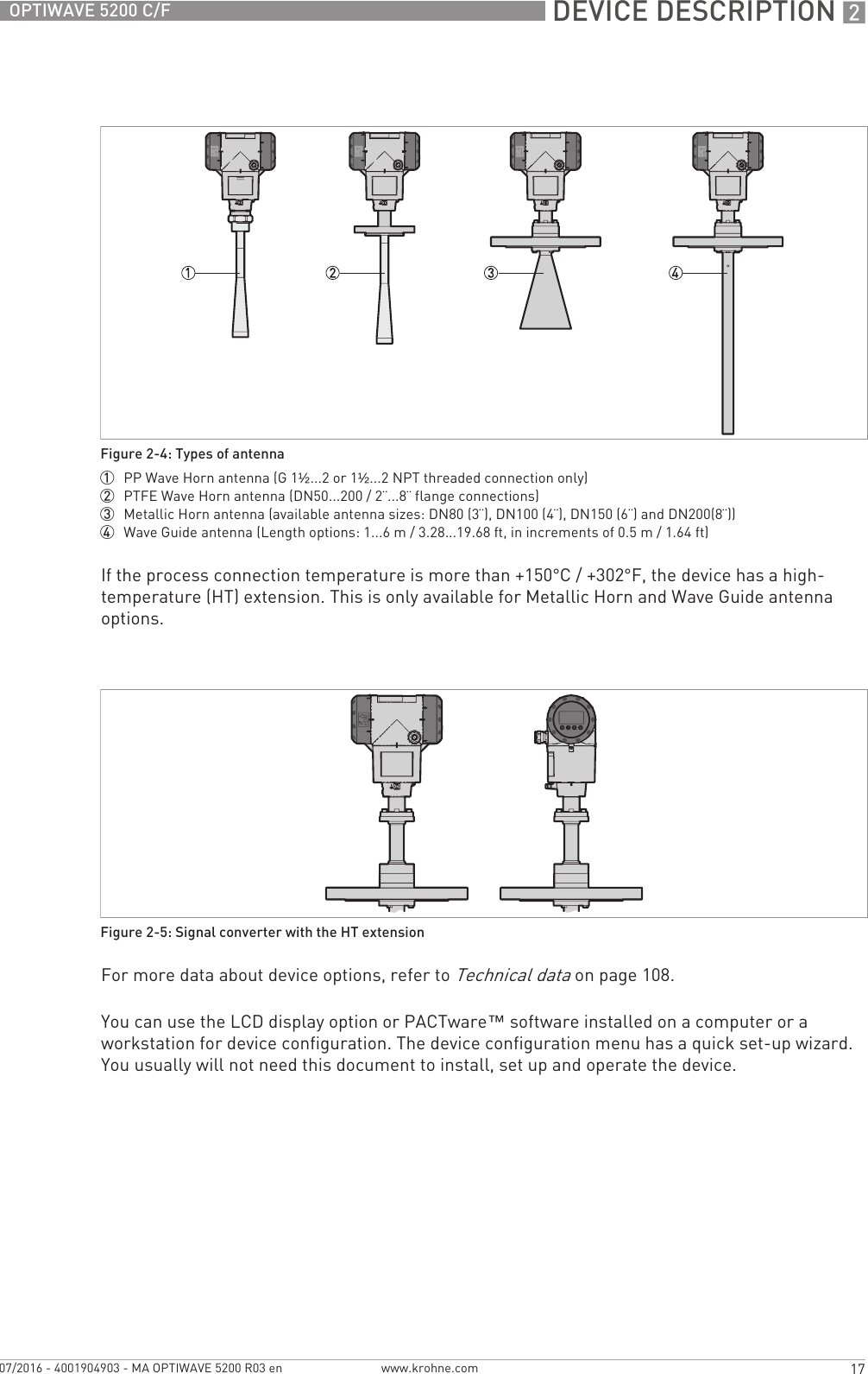
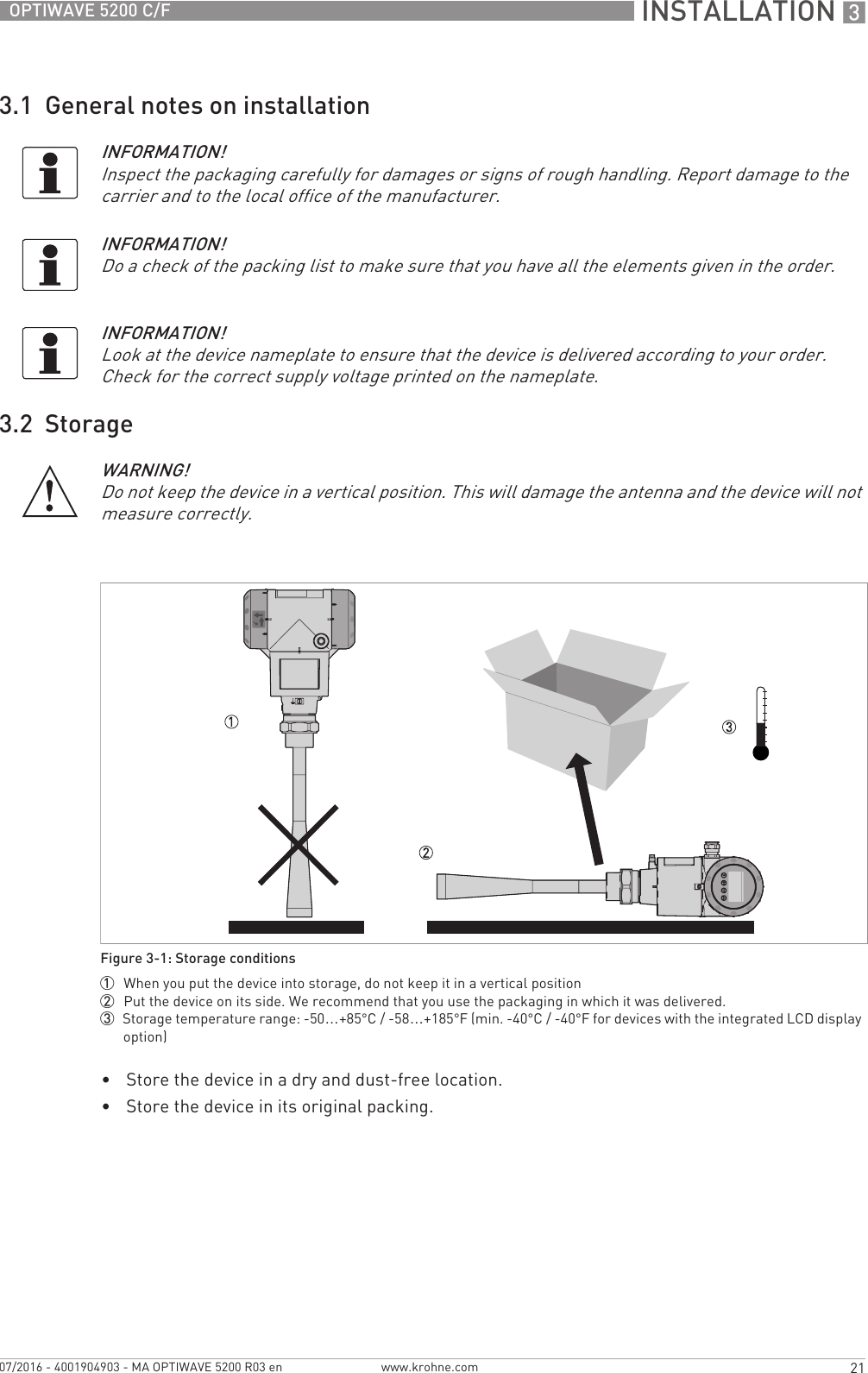
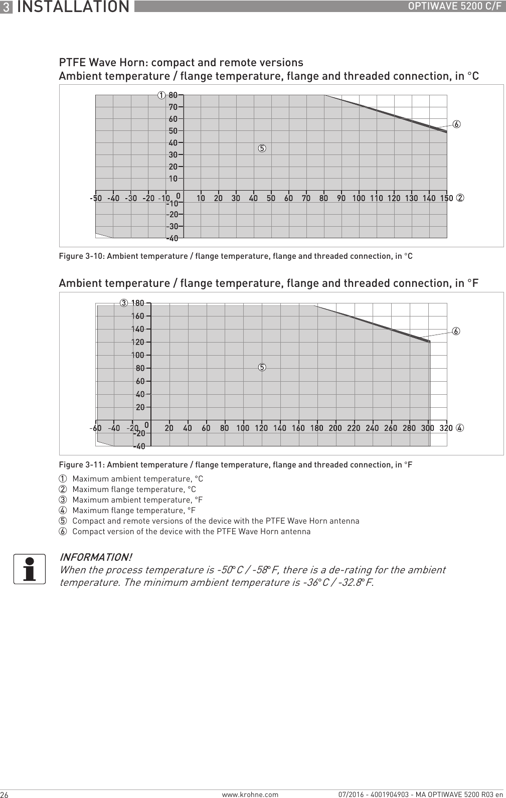
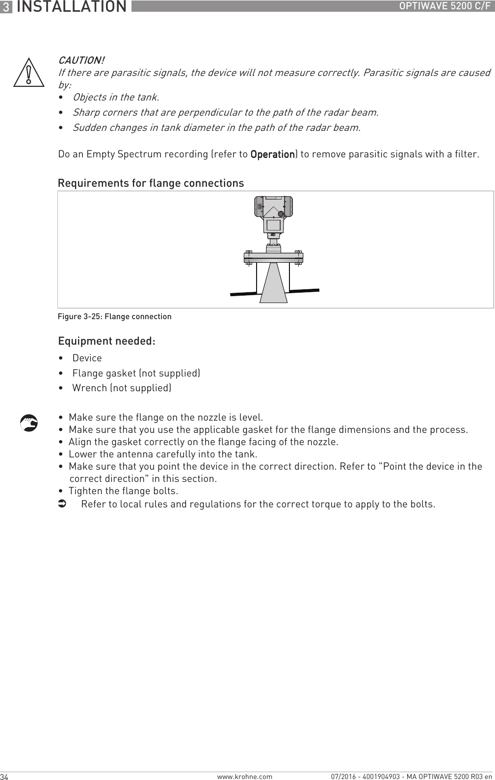
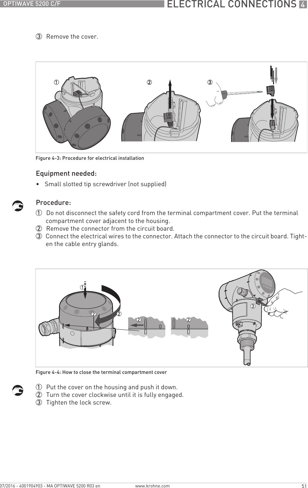
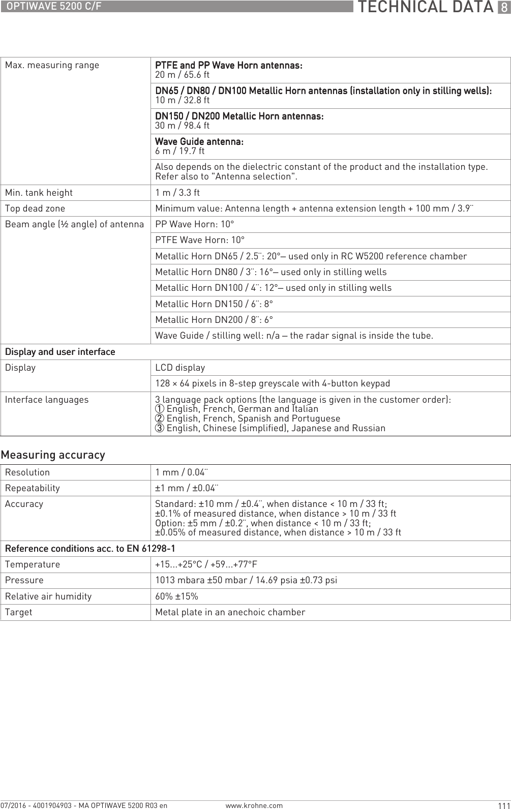
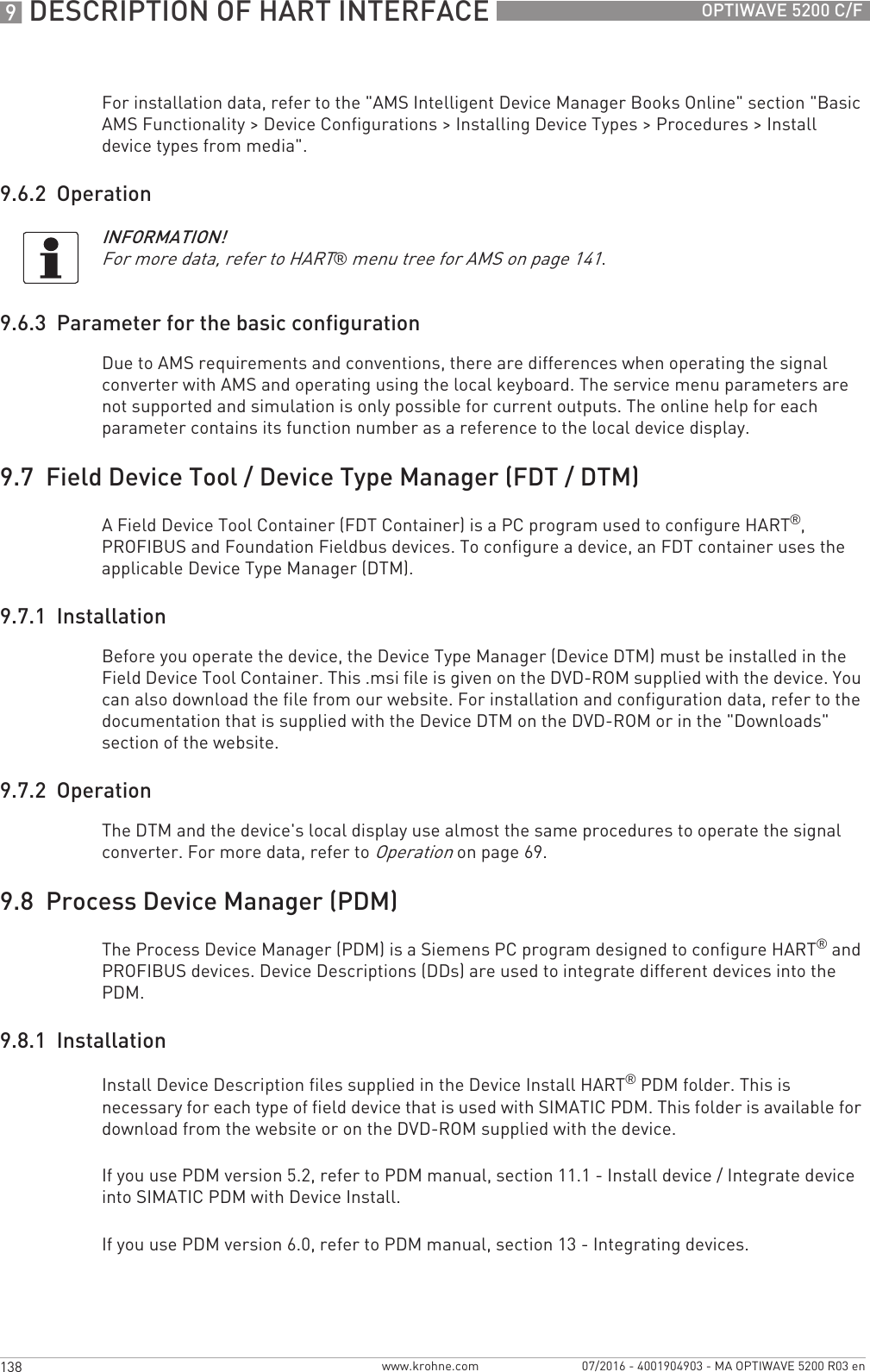
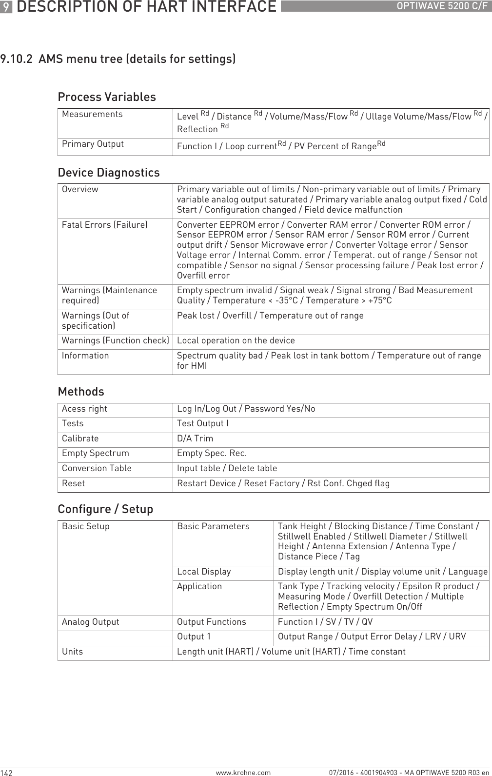
![START-UP 567OPTIWAVE 5200 C/Fwww.krohne.com07/2016 - 4001904903 - MA OPTIWAVE 5200 R03 en5.3.2 Functions of keypad buttonsFor data on keypad functions, refer to Normal mode on page 69.5.4 Remote communication with PACTware™PACTware™ displays measurement information clearly and lets you configure the device from a remote location. It is an Open Source, open configuration software for all field devices. It uses Field Device Tool (FDT) technology. FDT is a communication standard for sending information between the system and the field device. This standard agrees with IEC 62453. Field devices are easily integrated. Installation is supported by a user-friendly Wizard.Install these software programs and equipment:•Microsoft® .NET Framework version 1.1 or later.•PACTware.Figure 5-2: Local display screen layout in configuration mode1 Function name2 Configuration mode symbol3 Menu numberKeypad button Function [Right] Normal mode:Normal mode:Normal mode:Normal mode: Enter Information menu (Enter Configuration mode)Configuration mode:Configuration mode:Configuration mode:Configuration mode: Move cursor to the right [Return / Escape] Normal mode:Normal mode:Normal mode:Normal mode: Change units (m, cm, mm, in, ft)Configuration mode:Configuration mode:Configuration mode:Configuration mode: Exit [Down] Normal mode:Normal mode:Normal mode:Normal mode: Change measurement type (distance, level , output (%), output (mA), conversion, ullage conversion, reflection) 1Configuration mode:Configuration mode:Configuration mode:Configuration mode: Decrease value or change parameter [Up] Normal mode:Normal mode:Normal mode:Normal mode: Change measurement type (distance, level , output (%), output (mA), conversion, ullage conversion, reflection) 1Configuration mode:Configuration mode:Configuration mode:Configuration mode: Increase value or change parameter1If you have made a strapping table in menu item 2.8.1 INPUT TABLE for volume or mass measurement, "Conversion" and "Ullage Conv." will be shown in the list of measurement types](https://usermanual.wiki/KROHNE/FMCW10G52.User-Manual-EN-JH5FMCW10G52-pdf/User-Guide-4017651-Page-67.png)
![OPERATION 671OPTIWAVE 5200 C/Fwww.krohne.com07/2016 - 4001904903 - MA OPTIWAVE 5200 R03 en6.3.2 How to get access to the commissioning menuThe commissioning menu contains the menu items that are necessary for most configurations of the device. The menu items are divided into 2 groups: "Parameters" and "Empty Spectrum Recording". The "Parameters" group lets the supervisor set the tank height, tank type (process, storage etc.), output function, output current range, 4 mA output setting, 20 mA output setting, error delay and tag name. "Empty Spectrum Recording" is a procedure that finds interference signals in the tank and uses a filter to remove them from the measurement data.Do the steps that follow:• Push the [>>>>] button.iThis shows the InformationInformationInformationInformation menu. The InformationInformationInformationInformation menu is read only and does not have password security.• Push the [] button one time to scroll up to the SupervisorSupervisorSupervisorSupervisor menu.iThe screen shows the text "2.0.0 SUPERVISOR".• Push the [>>>>] button one time.iThe screen shows a line. You must enter the password. Push the buttons under the display screen 6 times (in total and in a given order) to get access to Configuration mode.• Type in the password. The factory-set password is [>>>>], [^^^^], [], [], [>>>>] and [^^^^].iThe device shows the text "2.1.0 COMMISSION.".• Push [>>>>]. Do the basic configuration of the device in the "'Parameters" menu. For more data on the procedure, refer to Quick Setup (Parameters) on page 83. Push [^^^^] at the end of each step of the procedure to continue to the next step.• Push [] to go to menu item 2.1.2 EMP.SPEC.REC. Push [>>>>] to start the empty spectrum recording procedure. For more data, refer to Empty spectrum recording on page 85.CAUTION!SIL-approved devices:SIL-approved devices:SIL-approved devices:SIL-approved devices: For data about critical device parameters, refer to the Safety Manual.INFORMATION!It is not possible to enter the 3.0.0 SERVICE and 4.0.0 MASTER menus. These menus are for factory calibration and approved personnel only.CAUTION!SIL-approved devices: For data about critical device parameters for SIL approval, refer to the Safety Manual (SIL approval).INFORMATION!HOW TO SET THE SUPERVISOR PASSWORD TO "ON" OR "OFF"The supervisor password is set to "on" by default. If it is necessary to set this function to "off", refer to Function description on page 76, Table 2: Supervisor menu, menu item PSWD YES/NO (2.7.4).INFORMATION!HOW TO CHANGE THE SUPERVISOR PASSWORDYou can change the password for the supervisor menu. For more data, refer to Function description on page 76, Table 2: Supervisor menu, menu item PASSWORD (2.7.5).](https://usermanual.wiki/KROHNE/FMCW10G52.User-Manual-EN-JH5FMCW10G52-pdf/User-Guide-4017651-Page-71.png)
![OPERATION 675OPTIWAVE 5200 C/Fwww.krohne.com07/2016 - 4001904903 - MA OPTIWAVE 5200 R03 enThis is what you see when you select a menu item that has a value. The functions of the buttons are given in the table that follows:Function of buttons in menu items that have valuesHow to save settings changed in the supervisor menu (menu 2.0.0)• When you have changed parameters in all the necessary menu items, push [^^^^] to accept the new parameter.• Push [^^^^] to go back to the "STORE" screen.• The device will ask you to save or cancel your settings. Push [] or [] to select STORE YESSTORE YESSTORE YESSTORE YES or STORE NOSTORE NOSTORE NOSTORE NO. Push [^^^^] to accept or reject the new settings.iThe display goes back to Normal mode.Values in menu itemsFigure 6-3: Values in menu items1 Menu item with values stored at this time (first screen)2 Push [>>>>] again to change the values. A cursor shows on the first digit.3 Menu item name4 Cursor on the selected digitButton Description FunctionRight•Enter the menu item and see the value stored at this time.•Enter the menu item configuration level to change the value.•Move the cursor to the next digit on the right. If the cursor is on the last digit, push [>>>>] again to go back to the first digit.Enter / Esc (Escape) Accept the value and go back to the sub-menu.Down Decrease the digit value.Up Increase the digit value.](https://usermanual.wiki/KROHNE/FMCW10G52.User-Manual-EN-JH5FMCW10G52-pdf/User-Guide-4017651-Page-75.png)
![6 OPERATION 76 OPTIWAVE 5200 C/Fwww.krohne.com 07/2016 - 4001904903 - MA OPTIWAVE 5200 R03 en6.3.5 Function description1.0.0 Information (Info.) menu2.0.0 Supervisor menuMenu No.Function Function description Selection list or range of valuesDefault1.1.0 IDENT.1.1.1 SERIAL NUM. The device serial number. Read only.1.1.2 CONV.FIRM.VER The converter firmware version. Read only.1.1.3 SEN.FIRM.VER The sensor firmware version. Read only.1.1.4 HMI.FIRM.VER The HMI (device display screen) firmware version. Read only.1.2.0 OUTPUT I1.2.1 SUMMARY I Push [>>>>] to read the setting at this time for the output function (OUTPUT FUNC.). Push [>>>>] again to read the settings for the output range (RANGE I), 4 mA setting (SCALE 4mA), 20 mA setting (SCALE 20mA), and error delay (ERROR DELAY).Read only.1.3.0 HISTORY1.3.1 ERROR RECORD A log of device errors. Push [>>>>] to read the errors. Push [] or [] to scroll up or down the list. Each error is identified by a code. Push [>>>>] again to show the number of incidents and the time since the last incident in days, hours, minutes and seconds. For more data about errors, refer to Status and error messages on page 93.Read only.Menu No.Function Function description Selection list or range of valuesDefault2.1.0 COMMISSION.2.1.1 PARAMETERS This starts a quick set-up procedure applicable to most applications. The supervisor can give the tank height (TANK HEIGHT), type of tank (TANK TYPE), output function (OUTPUT FUNC.), current output range (RANGE I), 4 mA setting (SCALE 4mA), 20 mA setting (SCALE 20mA), error delay (ERROR DELAY) and tag name (TAG NAME).CAUTION!CAUTION!CAUTION!CAUTION!Make sure that you do this procedure before you use the device. The settings in this procedure have an effect on the performance of the device.](https://usermanual.wiki/KROHNE/FMCW10G52.User-Manual-EN-JH5FMCW10G52-pdf/User-Guide-4017651-Page-76.png)
![OPERATION 677OPTIWAVE 5200 C/Fwww.krohne.com07/2016 - 4001904903 - MA OPTIWAVE 5200 R03 en2.1.2 EMP.SPEC.REC. Fixed and moving objects in the tank cause interference signals. Put them through this filter to correctly measure the tank contents. This menu item starts a quick set-up procedure. We recommend that the tank is empty or only filled to the minimum level before you do the procedure. We also recommend that if you installed the device on a tank that has equipment with parts that move (e.g. agitators), start the equipment. Push "Yes" at the end the procedure and set the STORE screen to "STORE YES" to use the data. For more data, refer to Empty spectrum recording on page 85. Refer also to "How to make a filter to remove radar signal interference" on page 92.2.2.0 TESTS2.2.1 SET OUTPUT After the selection of a parameter in this menu item, this sets the current output to a test value [mA]. The output will change to the given value, independent of the measured value. The current output will go back to the measured value when the display goes back to the menu level.3.5, 4, 6, 8, 10, 12, 14, 16, 18, 20 or 22 mA 3.5 mA2.2.2 DIAGNOSTIC This starts the hardware test. Push [>>>>] many times to show:•D1, the time of operation•T1, temperature of the electronic converter board•I1, loop current (internally measured value)•I2, load current (NOTE: this data is not available at this time)•V1, voltage 5.6 V. If the voltage is not 5.0<V1<5.7, speak to the supplier.•V2, voltage on capacitors. If the voltage is not 3.2<V2<3.4, speak to the supplier.•V3, voltage 3.3 V. If the voltage is not 3.2<V3<3.4, speak to the supplier.•C1, reset counter (watchdog timer). If C1>1, replace the signal converter.If an NE 107 symbol and a status marker are shown, refer to Device status (markers) on page 93.If you push [>>>>] again, the display goes back to the menu level.2.3.0 BASIC PARAM.2.3.1 TANK HEIGHT The distance from the flange face / thread stop of the tank connection down to the tank bottom. If the tank has a dish-shaped or conical bottom, the tank height is measured to a point on the tank bottom directly below the antenna. For more data about level measurement, refer to Level measurement on page 90. For more data about distance measurement, refer to Distance measurement on page 89.min: 0.5 m / 1.6 ft or 2.3.2 BLOCK. DIST. or 2.3.7 ANTENNA EXT.max: 30 m / 98.4 ft1Menu No.Function Function description Selection list or range of valuesDefault](https://usermanual.wiki/KROHNE/FMCW10G52.User-Manual-EN-JH5FMCW10G52-pdf/User-Guide-4017651-Page-77.png)
![OPERATION 681OPTIWAVE 5200 C/Fwww.krohne.com07/2016 - 4001904903 - MA OPTIWAVE 5200 R03 en2.7.0 DISPLAY2.7.1 LANGUAGE Data can be shown in any of the languages stored in the device. 9 languages are available in 3 packs: (1) English, French, German and Italian; (2) English, French, Spanish and Portuguese; (3) English, Chinese (simplified), Japanese and Russian42.7.2 LENGTH UNIT The length unit shown in normal mode. m, cm, mm, in (inches), ft (feet) m2.7.3 CONV UNIT Conversion unit. The length, volume, mass or flow rate conversion unit for the conversion table and shown in normal mode.m3, L, gal (US gallons), ImpG (Imperial gallons), ft3, bbl (oil barrel), kg, t, Ston, Lton, m, cm, mm, in, ft, m3/h, ft3/hL2.7.4 PSWD YES/NO If it is necessary to protect your settings in the supervisor menu with a password, set this menu item to YESYESYESYES.YES, NO YES2.7.5 PASSWORD This changes the password for the supervisor menu. Push the buttons up to 6 times in any order. This will be the new password. To confirm the change, enter the new password a second time. For more data, refer to Protection of the device settings on page 88.[>>>>], [^^^^], [], [], [>>>>] and [^^^^]2.7.6 CONTRAST The contrast control for the display screen. You can select a shade of grey between light grey (level 20) and black (level 54).min.-max: 20…54 362.8.0 CONV. TABLE2.8.1 INPUT TABLE The device uses a conversion table (strapping table) to convert measurements to volume, mass and flow rate readings. The readings are shown in normal mode. Give the number of entries on the table (min. 2; max. 30). Select an entry (01...30) and enter the level and the related volume / mass / flow rate value for that entry. Push [^^^^] to confirm the entry values. Continue the procedure until the device has data for all the entries. For more data, refer to How to configure the device to measure volume or mass on page 90.min. 2 entriesmax. 30 entries(level / volume, mass or flow rate)0 entries2.8.2 DELETE TABLE This menu item erases the data in the conversion table. YES, NO NOMenu No.Function Function description Selection list or range of valuesDefault](https://usermanual.wiki/KROHNE/FMCW10G52.User-Manual-EN-JH5FMCW10G52-pdf/User-Guide-4017651-Page-81.png)
![OPERATION 683OPTIWAVE 5200 C/Fwww.krohne.com07/2016 - 4001904903 - MA OPTIWAVE 5200 R03 en6.4 Further information on device configuration6.4.1 Quick Setup (Parameters)Use this procedure to change the tank height, tank type, output function, output range and give the top and bottom measuring limits. Values and parameters that can be changed are shown between the «... » marks in the illustrations that follow. Push the keypad buttons in the correct sequence:ProcedureCAUTION!Make sure that you do this procedure before you use the device. The settings in this procedure have an effect on the performance of the device.Screen Steps Description•[>>>>], [] and [>>>>]. Default screen.Enter configuration mode (2.0.0 SUPERVISOR).•[>>>>], [^^^^], [], [], [>>>>] and [^^^^]. Enter the password (the default password is shown). If it is necessary to change the password, refer to Function description on page 76, menu item 2.7.5 PASSWORD.•2× [>>>>] Push this button to start the quick set-up procedure.•[>>>>] to change the tank height (H).•[>>>>] to change the position of the cursor.•[] to decrease the value or [] to increase the value.•[^^^^] to confirm.The distance from the flange face / thread stop of the tank connection down to the tank bottom. If the tank has a dish-shaped or conical bottom, the tank height is measured to a point on the tank bottom directly below the antenna.•[] or [] for the selection of the conditions in which the device is used (Storage, Process, Agitator).•[^^^^] to confirm.If the surface of the product is flat, select "Storage". If the surface of the product is disturbed, select "Process". If the surface of the product is agitated with vortexes and foam, select "Agitator".](https://usermanual.wiki/KROHNE/FMCW10G52.User-Manual-EN-JH5FMCW10G52-pdf/User-Guide-4017651-Page-83.png)
![6 OPERATION 84 OPTIWAVE 5200 C/Fwww.krohne.com 07/2016 - 4001904903 - MA OPTIWAVE 5200 R03 en•[] or [] for the selection of the measurement name (Distance, Level, Conversion, Ullage Conv. or Reflection).•[^^^^] to confirm.The manufacturer sets the output function to “Level” before delivery.If it is necessary to measure volume, ullage volume, mass or ullage mass (Conversion or Ullage Conv.), refer to How to configure the device to measure volume or mass on page 90.•[] or [] for the selection of the current output range (4-20 mA/3.6E, 4-20, 3.8-20.5/3.6E, etc.).•[^^^^] to confirm.•[>>>>] to change Scale 4 mA.•[>>>>] to change the position of the cursor.•[] to decrease the value or [] to increase the value.•[^^^^] to confirm.Use this step to give the 4 mA output setting (0% limit) in the tank. Refer to the illustrations that follow. Illustration 1 shows the settings for level. Illustration 2 shows the settings for distance.•[>>>>] to change Scale 20 mA.•[>>>>] to change the position of the cursor.•[] to decrease the value or [] to increase the value.•[^^^^] to confirm.Use this step to give the 20 mA output setting (100% limit) in the tank. Refer to the illustrations that follow. Illustration 1 shows the settings for level. Illustration 2 shows the settings for distance.•[] or [] for the selection of the error delay (0 s, 10 s, 20 s, 30 s, 1 mn, 2 mn, 5mn or 15mn).•[^^^^] to confirm.The time after which the current output changes to an error value. The error value shows that there is a measurement error.Screen Steps Description](https://usermanual.wiki/KROHNE/FMCW10G52.User-Manual-EN-JH5FMCW10G52-pdf/User-Guide-4017651-Page-84.png)
![OPERATION 685OPTIWAVE 5200 C/Fwww.krohne.com07/2016 - 4001904903 - MA OPTIWAVE 5200 R03 en6.4.2 Empty spectrum recordingThe empty spectrum recording procedure is important for the performance of the device. We recommend that the tank is empty or only filled to the minimum level before you do the procedure.Use this procedure (menu item 2.1.2 EMP.SPEC.REC.) if there are fixed and moving objects in the tank that can cause parasitic signals. The device does a scan for objects that do not change their vertical positions in the tank (heating tubes, agitators, fuel assemblies etc.) and records the data. The device can then use this data to put the measurement signal through a filter (empty spectrum).When the empty spectrum filter is on (when menu item 2.3.12 EMP.SPEC.EN. is set to "on"), it will ignore the parasitic signals. Because the device records the data from the procedure, it is also not necessary to do the procedure again if you de-energize the device.Before you do the empty spectrum recording procedure, install the device on the tank. For more data about how to install the device, refer to Installation on page 21.Values and parameters that can be changed are shown between the «... » marks in the illustrations that follow. Push the keypad buttons in the correct sequence:Procedure•[>>>>] to change the tag name.•[>>>>] to change the position of the cursor.•[] to decrease the alphanumeric value (A, B, ..., 1, 2, ...) or [] to increase the alphanumeric value.•[^^^^] to confirm.The device has an identification code (tag name). The supervisor can enter a maximum of 8 numbers or letters.•2× [^^^^] to confirm.•[] or [] for the selection of the save option (STORE NO or STORE YES).•[^^^^] to confirm.Set to STORE YES to save and use the data. Set to STORE NO to cancel the changes to the device settings.Screen Steps DescriptionCAUTION!Make sure that the tank is empty or only filled to the minimum level.Screen Steps Description•[>>>>], [] and [>>>>]. Default screen.Enter configuration mode (2.0.0 SUPERVISOR).•[>>>>], [^^^^], [], [], [>>>>] and [^^^^]. Enter the password (the default password is shown). If it is necessary to change the password refer to Function description on page 76, menu item 2.7.5 PASSWORD.](https://usermanual.wiki/KROHNE/FMCW10G52.User-Manual-EN-JH5FMCW10G52-pdf/User-Guide-4017651-Page-85.png)
![6 OPERATION 86 OPTIWAVE 5200 C/Fwww.krohne.com 07/2016 - 4001904903 - MA OPTIWAVE 5200 R03 en•[>>>>], [] and [>>>>] Push these buttons to start the empty spectrum recording procedure.•[>>>>] for the selection of YES or [] for the selection of NO.Have you completely filled the tank?Have you completely filled the tank?Have you completely filled the tank?Have you completely filled the tank?If the tank is full, it is not possible to complete this procedure. The tank must be partially filled or empty. Push [>>>>] to go back to the start of the empty spectrum recording procedure.•Push [>>>>] after you start equipment in the tank with parts that move.Please activate moving parts!Please activate moving parts!Please activate moving parts!Please activate moving parts!If you installed the device on a tank that has equipment with parts that move (e.g. agitators), start the equipment.CAUTION!CAUTION!CAUTION!CAUTION!Make sure that you start all of the equipment in the tank with parts that move, before you continue to the subsequent step.•[>>>>] for the selection of "Partially filled" or [] for the selection of "Empty".Is your tank partially filled or empty?Is your tank partially filled or empty?Is your tank partially filled or empty?Is your tank partially filled or empty?If the tank is partially filled, the device will scan for the first reflection in the tank. Continue to the subsequent step. NOTE: If you set this step to "Partially filled", but the tank is empty, the device will show the error message "Failure! Pulse Lost". Push one of the keypad buttons to go back to the start of the Snapshot procedure.If the tank is empty, the scan will start immediately. Ignore the subsequent step.•[>>>>] to change the measuring distance.•[>>>>] to change the position of the cursor.•[] to decrease the value or [] to increase the value.•[^^^^] to confirm.Measuring DistanceIf the tank is partially filled, type in a distance shorter than that between the flange and the tank contents.•[] or [] to change the parameter ("Maximum" or "Average".•[^^^^] to confirm.Type of empty spectrumType of empty spectrumType of empty spectrumType of empty spectrumUse the average value for tanks which contain fixed objects only. Use the maximum value for tanks which contain many objects or moving objects.Recording in progressRecording in progressRecording in progressRecording in progressReading in progressReading in progressReading in progressReading in progressThe device does a scan for objects that do not change their vertical positions in the tank (heating tubes, agitators, fuel assemblies etc.) and records the data.•Push [>>>>] to make a selection from the available spectra.•[^^^^] to confirm.This shows a set of spectra (signals found in the tank). It also gives the amplitude and location of each signal.•[>>>>] to set to "Yes". [] to set to "No". Do you want to save the spectrum?Do you want to save the spectrum?Do you want to save the spectrum?Do you want to save the spectrum?Set to "Yes" to use the data. Set to "No" to erase the data.Screen Steps Description](https://usermanual.wiki/KROHNE/FMCW10G52.User-Manual-EN-JH5FMCW10G52-pdf/User-Guide-4017651-Page-86.png)
![OPERATION 687OPTIWAVE 5200 C/Fwww.krohne.com07/2016 - 4001904903 - MA OPTIWAVE 5200 R03 en6.4.3 TestUse this procedure to test the loop current. Values and parameters that can be changed are shown between the «... » marks in the illustrations that follow. Push the keypad buttons in the correct sequence:ProcedureScreen Step DescriptionDefault screen.•[>>>>], [] and [>>>>].•Enter the password: [>>>>], [^^^^], [], [], [>>>>] and [^^^^].•[^^^^]•[].•[>>>>].•[>>>>].•[] to decrease the value or [] to increase the value.•[^^^^] to confirm.This step sets the loop current value. Make a selection from 3.5, 4, 6, 8, 10, 12, 14, 16, 18, 20 or 22 mA.•[^^^^] 3 times to go back to the default screen.The loop current goes back to initial value.Default screen.](https://usermanual.wiki/KROHNE/FMCW10G52.User-Manual-EN-JH5FMCW10G52-pdf/User-Guide-4017651-Page-87.png)
![6 OPERATION 88 OPTIWAVE 5200 C/Fwww.krohne.com 07/2016 - 4001904903 - MA OPTIWAVE 5200 R03 en6.4.4 Protection of the device settingsThe menu item PASSWORD (2.7.5) lets you change the supervisor menu password.How to change the supervisor menu password• After you enter the supervisor menu, push 6 × [], [>>>>] and 4 × [] to go to the menu item PASSWORD (2.7.5).• Enter the new 6-character password (push the 4 buttons in any sequence).• Enter the new 6-character password again.iIf the second entry is the same as the first, the device will go back to the sub-menu list (2.7).If the second entry is not the same as the first, the device will not go back to the sub-menu list. Push [^^^^] to start the password sequence again and enter the new 6-character password 2 times.• Push [^^^^] to go back to the "STORE" screen.• Push [] or [] to set the screen to STORE YESSTORE YESSTORE YESSTORE YES and push [^^^^].iThe device will save the new password and go back to normal mode.How to set the supervisor password to "on" or "off"The supervisor password is set to "on" by default. If it is necessary to set this function to "off", refer to Function description on page 76, Table 2: Supervisor menu, menu item PSWD YES/NO (2.7.4).6.4.5 HART® network configurationThe device uses HART® communication to send information to HART®-compatible equipment. It can operate in either point-to-point or multidrop mode. The device will communicate in multidrop mode if you change the address.How to change from point-to-point to multidrop mode• Enter the supervisor menu.• Push [>>>>], 5 × [] and [>>>>] to go to menu item ADDRESS (2.6.1).• Push [>>>>] to change the value. Enter a value between 1 and 63 and push [^^^^] to confirm (refer to the caution before this procedure).• Push [^^^^] to go back to the "STORE" screen.• Push [] or [] to set the screen to STORE YESSTORE YESSTORE YESSTORE YES and push [^^^^].iThe output is set to multidrop mode. The current output is set to 4 mA. This value does not change in multidrop mode.INFORMATION!Make a note of the password and keep it in a safe place. If you lose the password, please speak or write to your supplier.INFORMATION!For more data, refer to Networks on page 61.CAUTION!Make sure that the address for this device is different from others in the multidrop network.](https://usermanual.wiki/KROHNE/FMCW10G52.User-Manual-EN-JH5FMCW10G52-pdf/User-Guide-4017651-Page-88.png)
![OPERATION 689OPTIWAVE 5200 C/Fwww.krohne.com07/2016 - 4001904903 - MA OPTIWAVE 5200 R03 enHow to change from multidrop to point-to-point mode• Enter the supervisor menu.• Push [>>>>], 5 × [] and [>>>>] to go to menu item ADDRESS (2.6.1).• Push [>>>>] to change the value. Enter the value 0 and push [^^^^] to confirm.• Push [^^^^] to go back to the "STORE" screen.• Push [] or [] to set the screen to STORE YESSTORE YESSTORE YESSTORE YES and push [^^^^].iThe output is set to point-to-point mode. The current output changes to a range of 4...20 mA or 3.8...20.5 mA (this range is set in menu item RANGE I (2.4.2)).6.4.6 Distance measurementThe device displays distance measurements when the output function is set to "Distance". Menu items related to distance measurement are:•Output Function (2.4.1)•Tank Height (2.3.1)•Blocking Distance (2.3.2)For more data about the menu items, refer to Function description on page 76, table 2. Supervisor menu.CAUTION!If the distance for 4 mA is set in the blocking distance, the device will not be able to use the full current output range.Figure 6-4: Distance measurement1 Tank Height (2.3.1)2 Blocking Distance (2.3.2)3 4mA Setting (2.4.3)4 20 mA Setting (2.4.4)5 Maximum effective measuring range6 Non-measurement zone](https://usermanual.wiki/KROHNE/FMCW10G52.User-Manual-EN-JH5FMCW10G52-pdf/User-Guide-4017651-Page-89.png)
![OPERATION 691OPTIWAVE 5200 C/Fwww.krohne.com07/2016 - 4001904903 - MA OPTIWAVE 5200 R03 enHow to prepare a strapping table (conversion table)• Enter the supervisor menu.• Push [>>>>], 6 × [], [>>>>] and [] to go to 2.7.2 LENGTH UNIT.• Push [] and [] to find the length unit that you will use in the table.• Push [^^^^] to go to the sub-menu level.• Push [] to go to 2.7.3 CONV UNIT (conversion unit)• Push [] and [] to find the conversion unit that you will use in the table.• Push [^^^^] to go to the sub-menu level and then [] and [>>>>] to go to the menu item 2.8.1 INPUT TAB• Push [>>>>] to make the strapping table. Enter the table entry number (01).• Enter the length value and push [^^^^].• Enter the conversion value and push [^^^^].• Push [>>>>] to enter the subsequent table entry number (02, 03, ..., 30).• Repeat the last 3 steps to complete the table.• Push [^^^^] to go back to the "STORE" screen.• Push [] or [] to set the screen to STORE YESSTORE YESSTORE YESSTORE YES and push [^^^^].iThe device will store the data for the strapping table and go back to normal mode.The device will give more accurate volume readings if you give more conversion data in these areas:•Surfaces with curves.•Sudden changes in the cross section.Refer also to the illustration that follows:Figure 6-6: A plot of points for a volume or mass table1 Tank with reference points2 Tank model with plotted points](https://usermanual.wiki/KROHNE/FMCW10G52.User-Manual-EN-JH5FMCW10G52-pdf/User-Guide-4017651-Page-91.png)
![6 OPERATION 92 OPTIWAVE 5200 C/Fwww.krohne.com 07/2016 - 4001904903 - MA OPTIWAVE 5200 R03 enHow to delete a volume or mass table• Enter the supervisor menu.• Push 7 × [], [>>>>], and [] to go to 2.8.2 DELETE TABLE.• Push [>>>>] and [] to set the parameter to YESYESYESYES.• Push [^^^^] to go back to the "STORE" screen.• Push [] or [] to set the screen to STORE YESSTORE YESSTORE YESSTORE YES and push [^^^^].iThe device will delete the data for the strapping table and go back to normal mode. The "CONVERSION" and "ULLAGE CONV." data are not available in normal mode.6.4.9 How to make a filter to remove radar signal interferenceIf the device measures level in a tank that contains obstructions (agitator, supports, heating pipes etc.), these objects can cause radar signal interference (parasitic signals). You can use the empty spectrum function (menu item 2.1.2) in the Commissioning menu to make a filter to remove radar signal interference.• After you enter the supervisor menu, push 2 × [>>>>] and [] to go to the menu item EMP.SPEC.REC. (2.1.2).• Do you have a completely filled tank? Select YesYesYesYes or NoNoNoNo and then push [^^^^].iIf you select YesYesYesYes, the device will not do the empty spectrum scan. Empty the tank and repeat the procedure.• Are all the moving parts switched on? Select YesYesYesYes or NoNoNoNo and then push [^^^^].• Is your tank partially filled or completely empty? Select Partially filledPartially filledPartially filledPartially filled or EmptyEmptyEmptyEmpty and then push [^^^^].INFORMATION!We recommend that you do an empty spectrum scan when the tank is empty and all the moving parts (agitators etc.) are in operation..Figure 6-7: How to make a filter to remove radar signal interference1 Empty tank before the device uses the empty spectrum scan (with a graph of reflections shown)2 Partially filled tank before the device uses the empty spectrum scan (with a graph of reflections shown)3 Partially filled tank after the device uses the empty spectrum scan (with a graph of reflections shown)4 Agitator blades location5 Tank bottom signal6 Agitator blades signals (interference signals) before the device does the empty spectrum scan7 Bad quality (mixed) signals of the liquid and the agitator blades before the device does the empty spectrum scan8 Reflected signal if the device uses the data from the empty spectrum scan. The device only uses the reflection on the surface of the liquid to measure distance.](https://usermanual.wiki/KROHNE/FMCW10G52.User-Manual-EN-JH5FMCW10G52-pdf/User-Guide-4017651-Page-92.png)
![OPERATION 693OPTIWAVE 5200 C/Fwww.krohne.com07/2016 - 4001904903 - MA OPTIWAVE 5200 R03 en• Measured distance. If the tank is partially filled, enter the distance to the product surface - 300 mm / 12¨. The device must include the tank contents when it filters the signal• Do you want to use the average value or the maximum value? Select AverageAverageAverageAverage or MaximumMaximumMaximumMaximum and then push [^^^^].iUse the maximum for tanks that have moving parts. Use the average value for tanks that do not have moving parts. The device will do an empty spectrum scan and then show the results on the signal screen.• Make a selection from the available spectra to identify the correct level signal. Push [^^^^].• Do you want to save the spectrum? Select YesYesYesYes or NoNoNoNo and then push [^^^^].iIf you select YesYesYesYes, the device will use the empty spectrum scan results to make a filter to remove radar signal interference.6.5 Status and error messages6.5.1 Device status (markers)If the device senses a change in device status, the display screen will show 1 or more status markers at the bottom right side of the display screen. The display screen will also show a symbol that agrees with NAMUR Recommendation NE 107 (Self-Monitoring and Diagnosis of Field Devices) and VDI/VDE 2650. This is shown at the top left side of the display screen. More data is given if you use PACTware™ software with the appropriate DTM on a PC. Error codes and data are shown on the device display screen and in the DTM.Menu item 2.2.2 DIAGNOSTIC (Configuration mode / Supervisor menu) supplies more data. This includes internal voltages, the loop current and the reset counter (watchdog timer). You can see this data on the device display screen and in the DTM.INFORMATION!For more data on empty spectrum scans, refer to Function description on page 76 – table 2: Supervisor (menu item 2.1.2).Figure 6-8: Status markers1 Device status (NAMUR NE 107 symbols)2 Symbol: Failure3 Symbol: Function check4 Symbol: Out of specification5 Symbol: Maintenance6 Status marker line (marker 3 is shown)7 When the status marker is on, a number is shown](https://usermanual.wiki/KROHNE/FMCW10G52.User-Manual-EN-JH5FMCW10G52-pdf/User-Guide-4017651-Page-93.png)
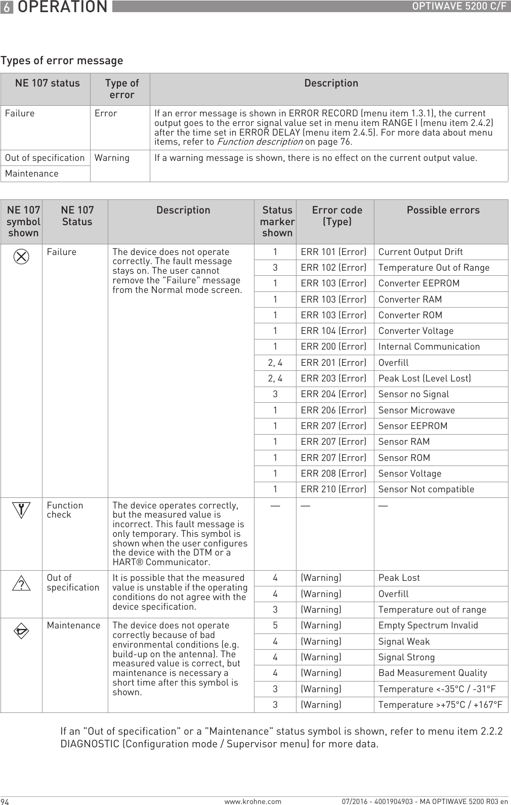
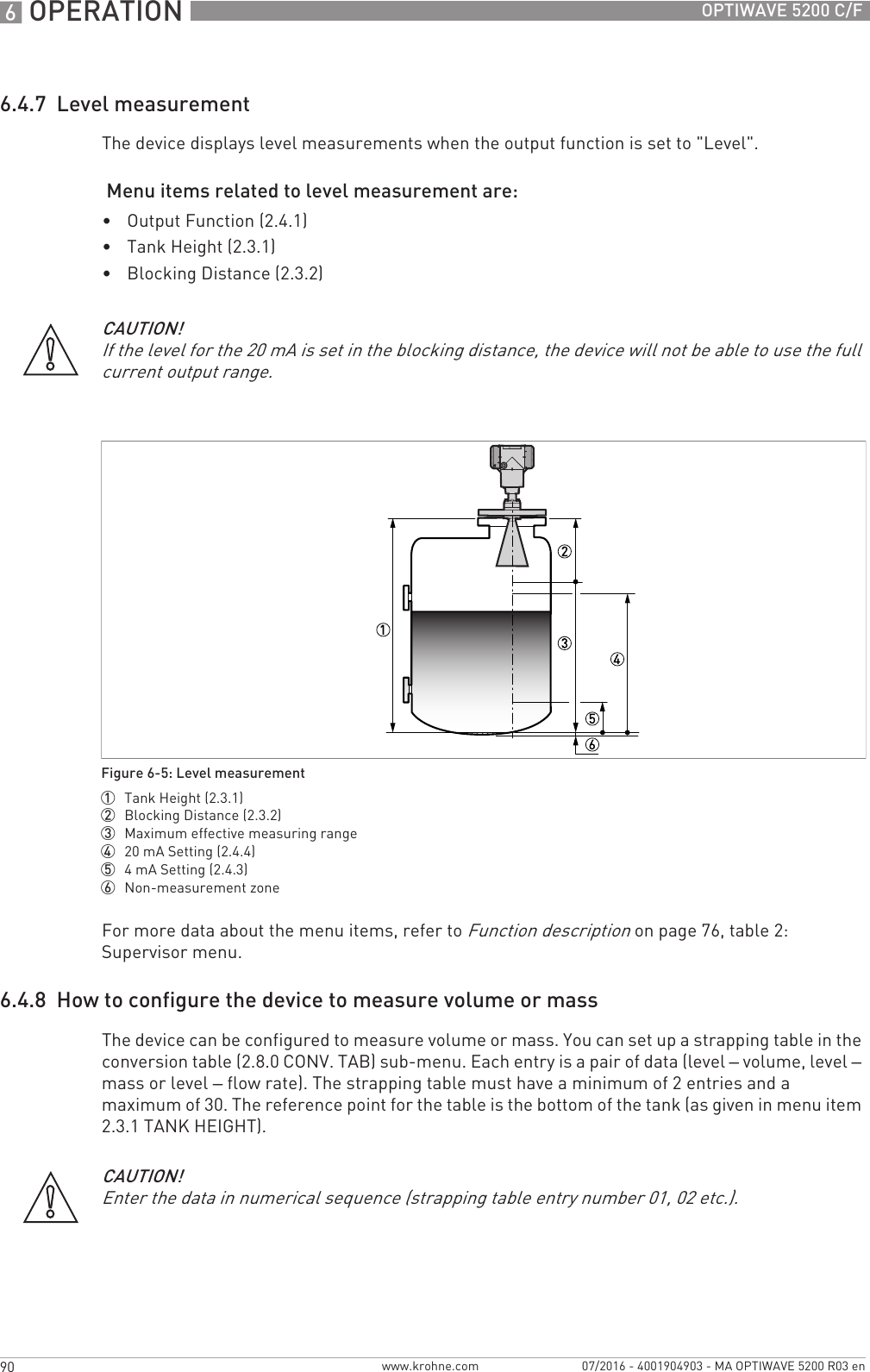
![OPERATION 695OPTIWAVE 5200 C/Fwww.krohne.com07/2016 - 4001904903 - MA OPTIWAVE 5200 R03 enFor data on errors, error records and error codes, refer to Error handling on page 95.6.5.2 Error handlingHow to find an error record• Push [>>>>] to enter configuration mode from normal mode.• Push [>>>>], 2 × [] and [>>>>] to go to menu item 1.3.1 ERROR RECORD.• Push 2 × [>>>>] to look at the error list. Push [] or [] for the selection of an error.iThe error record gives the number of times the error occurred and the time since the last error message.Description of errors and corrective actionsFigure 6-9: Error record data1 Error code for the error2 Number of times the error occurred3 Time since the last error record (2 days, 18 hours, 16 minutes and 43 seconds shown in this example)INFORMATION!The time since the error occurred is measured in Days (D), Hours (H), Minutes(') and Seconds ("). It only includes the time when the device is energized. The error is saved in the memory of the device when it is de-energized. The counter continues when the device is energized again.Error codeError Message Status marker shownCause Corrective actionFailure (NE 107 status signal)ERR 100 Device reset 1The device detected an internal error (watchdog timer issue). Record the data that is in menu item 2.2.2 DIAGNOSTIC (Configuration mode / Supervisor menu). Speak to the supplier.ERR 101 Current Output Drift 1The current output is not calibrated. Speak to the supplier to get the calibration procedure.1Hardware error. Replace the device.](https://usermanual.wiki/KROHNE/FMCW10G52.User-Manual-EN-JH5FMCW10G52-pdf/User-Guide-4017651-Page-95.png)
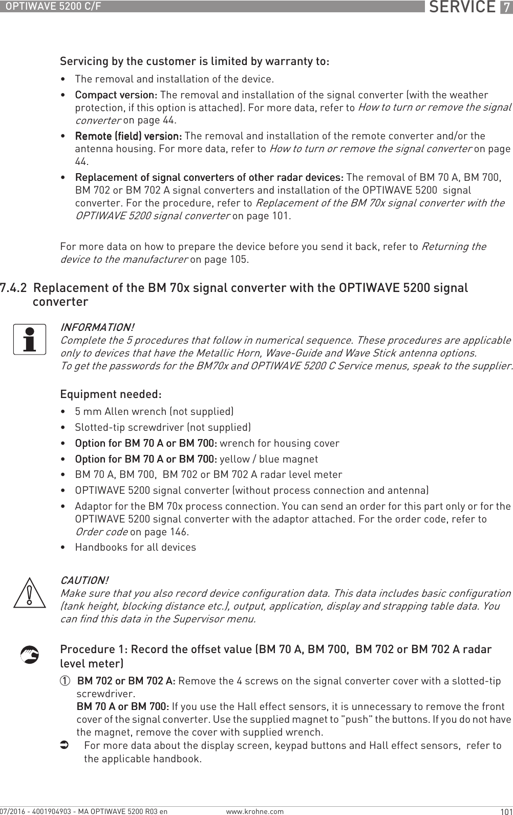
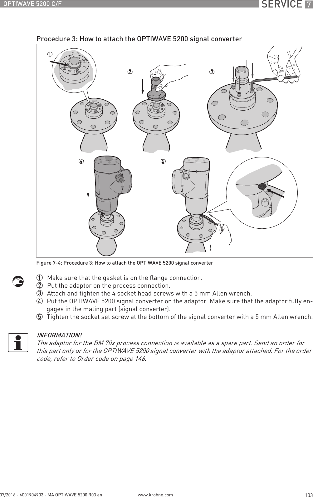
![7 SERVICE 102 OPTIWAVE 5200 C/Fwww.krohne.com 07/2016 - 4001904903 - MA OPTIWAVE 5200 R03 en2 Energize the device.iThe device is in operation and in normal mode.3 Push [^^^^] to go to the SERVICE menu.iThe display screen shows the text "Code 2".4 Give the password for the SERVICE menu. If you do not have the password, speak to the sup-plier.5 Push [>>>>], [] and [>>>>] to go to menu item 4.2.1 Offset. Record the offset value.6 Push 4 × [^^^^]. Push [] or [] for the selection of the save option (Store No, Store Yes or Re-turn). Set to "Store No" to cancel the changes to the device settings.7 Push [^^^^] to confirm.iThe device is in normal mode.8 De-energize the device.9 Remove the electrical cables.10 Attach the signal converter cover.1 Remove the 4 socket head screws at the bottom of the signal converter with a 5 mm Allen wrench. Keep the screws for the subsequent procedure.2 Remove the signal converter from the process connection. Make sure that the gasket stays on the flange connection.INFORMATION!If you cannot start the device, record the serial number on the device nameplate and contact the supplier. The supplier will give you the offset value.Procedure 2: How to remove the signal converter (BM 70 A, BM 700, BM 702 or BM 702 A radar level meters)Figure 7-3: Procedure 2: How to remove the signal converter (BM 70 A, BM 700, BM 702 or BM 702 A radar level meters)INFORMATION!The BM 702 A radar level meter is used as an example in this procedure.](https://usermanual.wiki/KROHNE/FMCW10G52.User-Manual-EN-JH5FMCW10G52-pdf/User-Guide-4017651-Page-102.png)
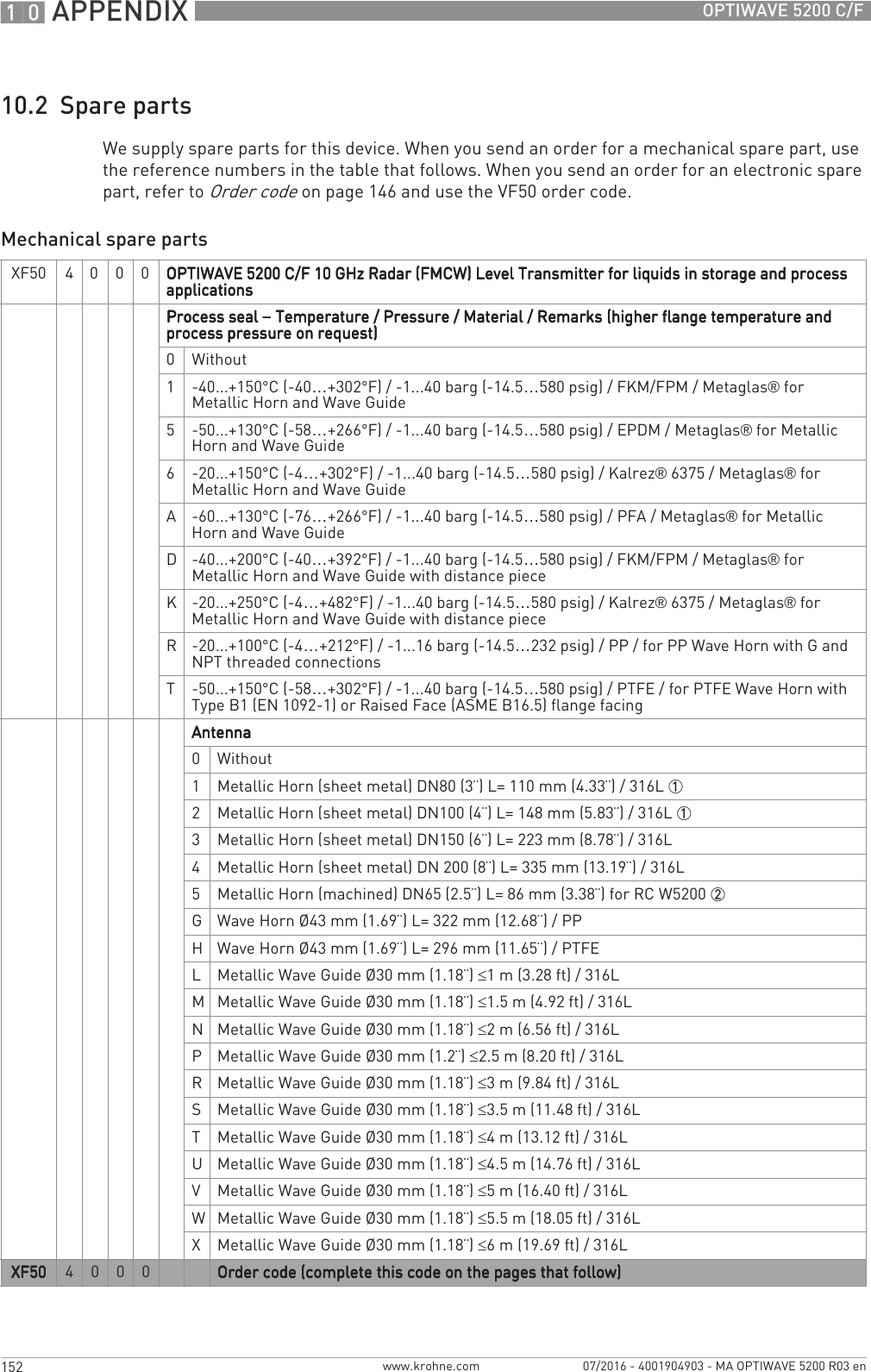
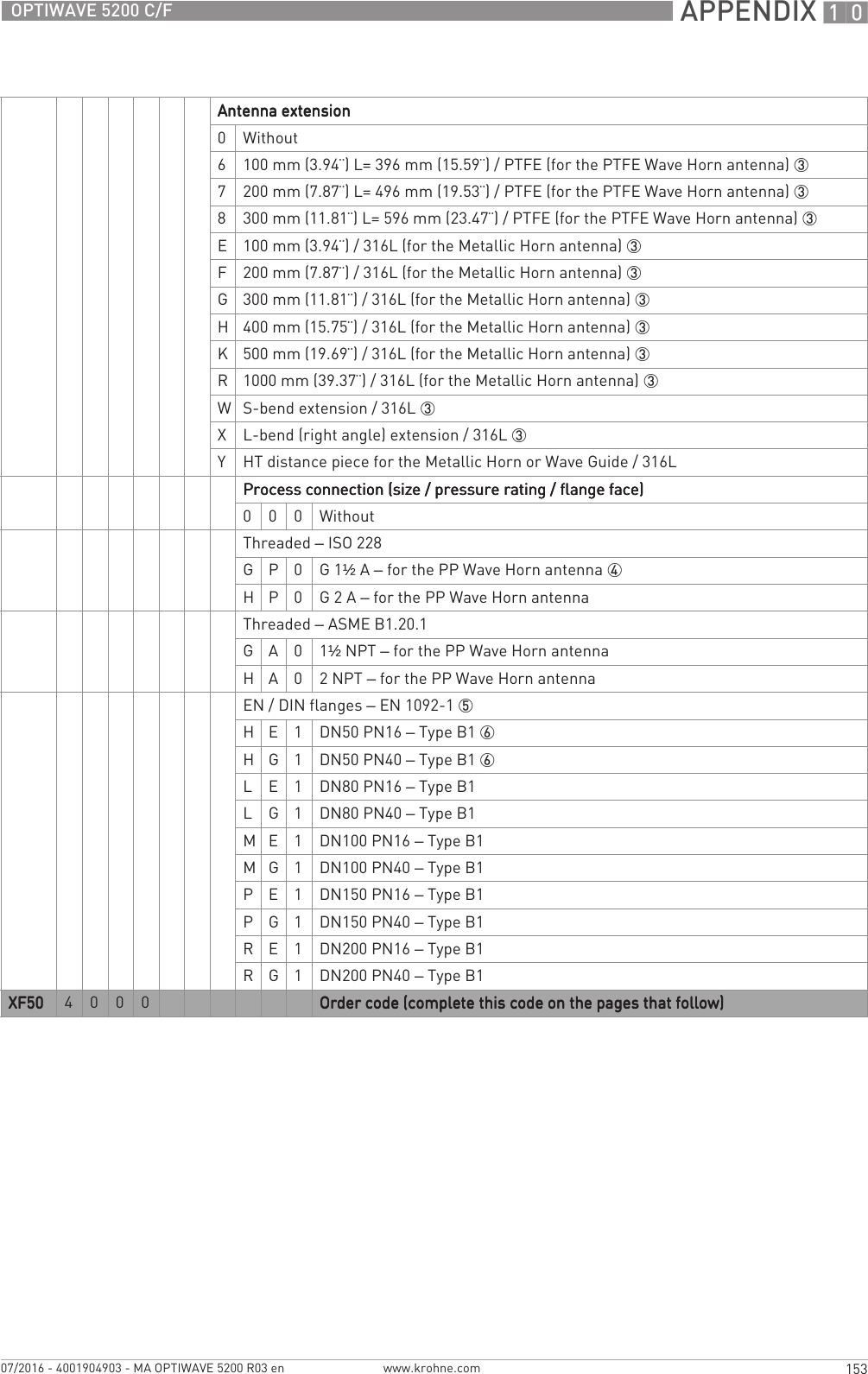
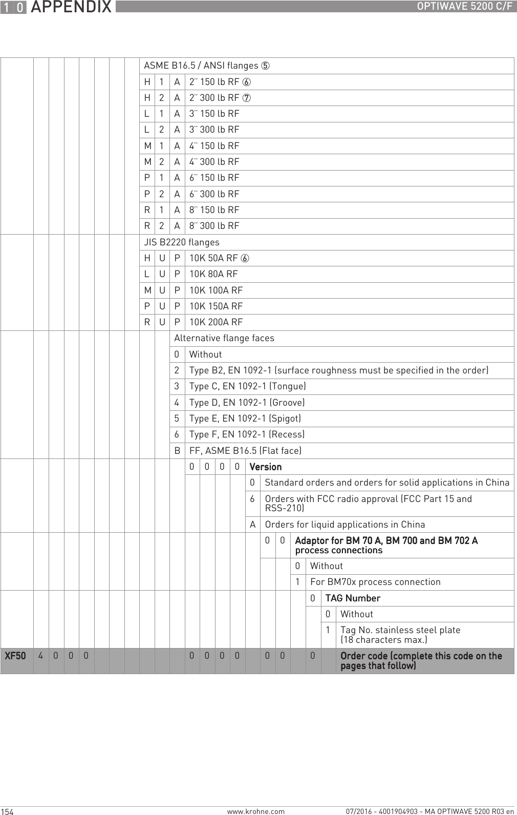
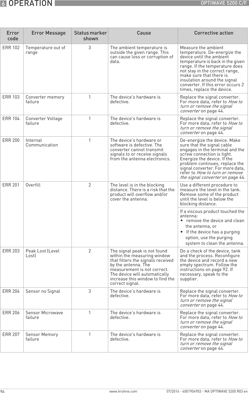
![7 SERVICE 104 OPTIWAVE 5200 C/Fwww.krohne.com 07/2016 - 4001904903 - MA OPTIWAVE 5200 R03 enProcedure 4: How to set the correct offset value (OPTIWAVE 5200)1 Energize the device.iThe device is in operation and in normal mode. It will not measure correctly until the new correction offset value is set in menu item 3.1.6 CORR.OFFSET. 2 Push [>>>>], 2 × [] and [>>>>] to go to the SERVICE menu (3.0.0).3 Give the password for the SERVICE menu. If you do not have the password, speak to the sup-plier.4 Push [>>>>] and 5 × [] to go to menu item 3.1.6 CORR.OFFSET (correction offset).5 Push [>>>>] to change the value. Enter the new correction offset value. For the applicable correc-tion offset value, refer to the table that follows.6 Push 4 × [>>>>]. Push [] or [] for the selection of the save option (STORE NO or STORE YES). Set to "STORE YES" to save and use the data.7 Push [^^^^] to confirm.iThe device is in normal mode. The device uses the new correction offset value.New correction offset values for the OPTIWAVE 5200Procedure 5: Device configuration (OPTIWAVE 5200)1 For the Quick Setup procedure, refer to Quick Setup (Parameters) on page 83. For more data about device configuration, refer to Operation on page 69.7.5 Spare parts availabilityThe manufacturer adheres to the basic principle that functionally adequate spare parts for each device or each important accessory part will be kept available for a period of 3 years after delivery of the last production run for the device.This regulation only applies to spare parts which are subject to wear and tear under normal operating conditions.7.6 Availability of servicesThe manufacturer offers a range of services to support the customer after expiration of the warranty. These include repair, maintenance, technical support and training.Device New correction offset valueBM 70 A, BM 700 BM 70x value - 148 mm 1BM 702 BM 70x value + 24 mm 1BM 702 A BM 70x value + 18 mm 11The BM 70x value is given in menu item 4.2.1 Offset. For more data, refer to Procedure 1 in this sub-section.CAUTION!You recorded device configuration data of the BM70x level meter before you attached the new signal converter. Make sure that you enter this data in the supervisor menu of the OPTIWAVE 5200.INFORMATION!For more precise information, please contact your local sales office.](https://usermanual.wiki/KROHNE/FMCW10G52.User-Manual-EN-JH5FMCW10G52-pdf/User-Guide-4017651-Page-104.png)
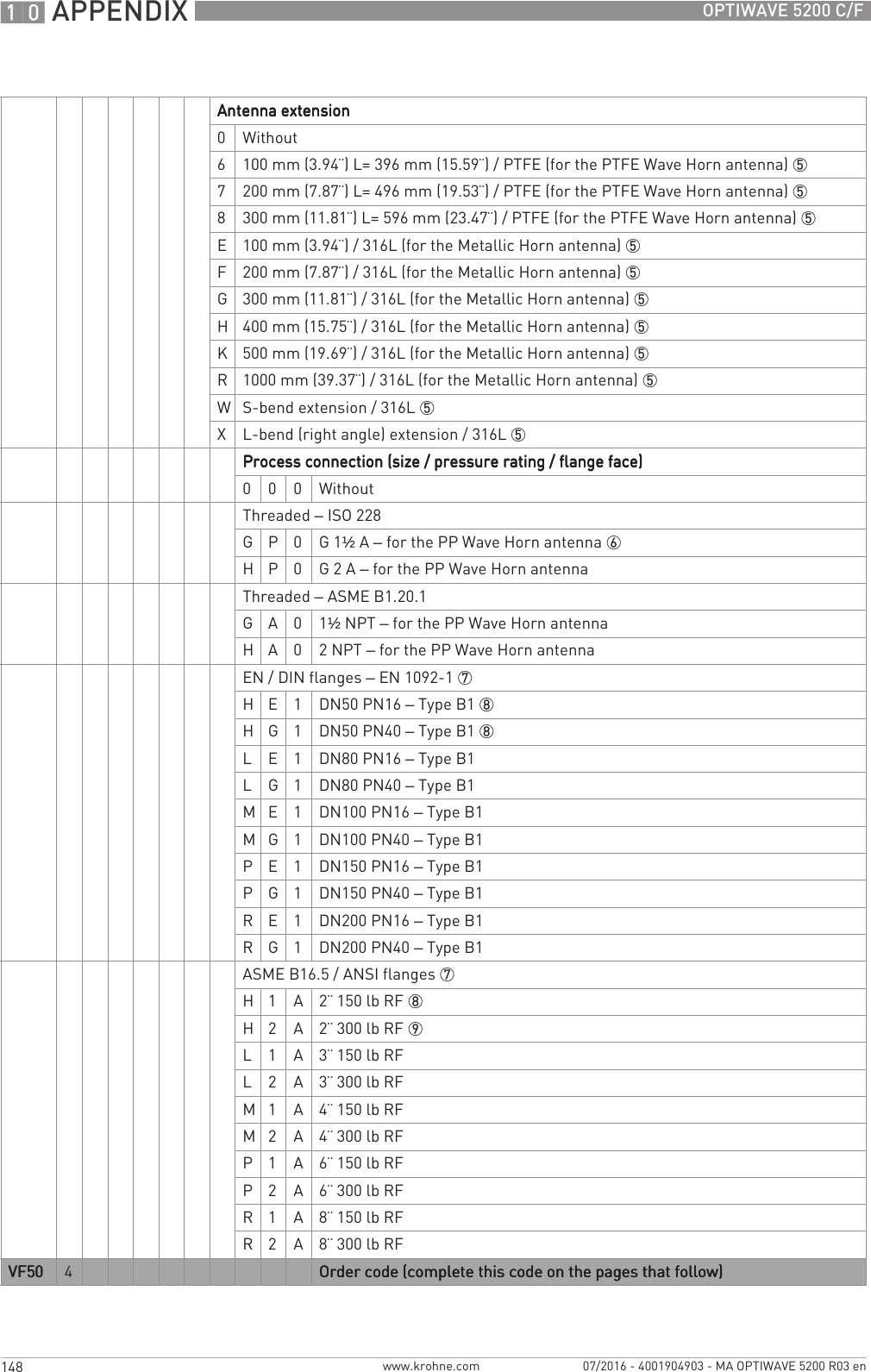
![TECHNICAL DATA 8113OPTIWAVE 5200 C/Fwww.krohne.com07/2016 - 4001904903 - MA OPTIWAVE 5200 R03 enAntenna options / Wetted materials PTFE Wave Horn antenna with a PTFE flange claddingPP Wave Horn antenna with a PP jacket/threaded process connectionStainless steel (1.4404 / 316L) Metallic Horn antenna with a PTFE process seal and an FKM/FPM, EPDM, Kalrez® 6375 or PFA O-ring gasketStainless steel (1.4404 / 316L) Wave Guide antennas with a PTFE process seal and an FKM/FPM, EPDM, Kalrez® 6375 or PFA O-ring gasketFeedthrough PP Wave Horn antenna: this is a single-piece antenna (the feedthrough is filled with PP)PTFE Wave Horn antenna: this is a single-piece antenna (the feedthrough is filled with PTFE)Metallic Horn and Wave Guide antennas: Dual process seal system – 1st seal: PTFE with O-ring gasket, 2nd seal: Metaglas® with O-ring gasket 2Cable gland Standard: noneOptions: Plastic (Non-Ex: black, Ex i-approved: blue); nickel-plated brass; stainless steelWeather protection (Option) Stainless steel (1.4404 / 316L)Process connectionsThread PP Wave Horn antenna: G 1½A...2A; 1½...2 NPTFlange versionFlange versionFlange versionFlange versionEN PTFE Wave Horn antenna: DN50…200 in PN16, PN40Metallic Horn and Wave Guide antennas: DN80…200 in PN16, PN40; others on requestASME PTFE Wave Horn antenna: 2¨…8¨ in 150 lb / 300 lbMetallic Horn and Wave Guide antennas: 3¨…8¨ in 150 lb / 300 lb; others on requestDN65 Metallic Horn antenna: 2¨ 300 lb for installation on the RC W5200 reference chamberJIS PTFE Wave Horn antenna: 50...150A in 10KMetallic Horn and Wave Guide antennas: 80…200A in 10K; others on requestOther Others on requestElectrical connectionsPower supply Terminals output Terminals output Terminals output Terminals output – Non-Ex / Ex i: Non-Ex / Ex i: Non-Ex / Ex i: Non-Ex / Ex i:11.5…30 VDC; min./max. value for an output of 22 mA at the terminalTerminals output Terminals output Terminals output Terminals output – Ex d: Ex d: Ex d: Ex d:13.5…36 VDC; min./max. value for an output of 22 mA at the terminalMaximum current 22 mACurrent output load Non-Ex / Ex i:Non-Ex / Ex i:Non-Ex / Ex i:Non-Ex / Ex i: RL [Ω] ≤ ((Uext -11.5 V)/22 mA). For more data, refer to Minimum power supply voltage on page 118.Ex d:Ex d:Ex d:Ex d: RL [Ω] ≤ ((Uext -13.5 V)/22 mA). For more data, refer to Minimum power supply voltage on page 118.Cable entry Standard: M20×1.5; Option: ½NPTCable gland Standard: noneOptions: M20×1.5 (cable diameter (non-Ex / Ex i: 6...7.5 mm / 0.24...0.30¨; Ex d: 6...10 mm / 0.24...0.39¨)); others are available on requestSignal cable – remote version None for non-Ex devices (4-wire shielded cable of max. length 100 m / 328 ft to be supplied by the customer). Supplied with all Ex-approved devices. For more data, refer to Remote device data on page 53Cable entry capacity (terminal) 0.5…2.5 mm²](https://usermanual.wiki/KROHNE/FMCW10G52.User-Manual-EN-JH5FMCW10G52-pdf/User-Guide-4017651-Page-113.png)
![TECHNICAL DATA 8115OPTIWAVE 5200 C/Fwww.krohne.com07/2016 - 4001904903 - MA OPTIWAVE 5200 R03 enExplosion protectionExplosion protectionExplosion protectionExplosion protectionATEX (Ex ia or Ex d or Ex tb)DEKRA 11ATEX0166 X Compact versionCompact versionCompact versionCompact versionII 1/2 G, 2 G Ex ia IIC T6...T2 Ga/Gb or Ex ia IIC T6...T2 Gb;II 1/2 D, 2 D Ex ia IIIC T90°C Da/Db or Ex ia IIIC T90°C Db;II 1/2 G, 2 G Ex d ia IIC T6...T2 Ga/Gb or Ex d ia IIC T6...T2 Gb;II 1/2 D, 2 D Ex ia tb IIIC T90°C Da/Db or Ex ia tb IIIC T90°C DbRemote version, transmitterRemote version, transmitterRemote version, transmitterRemote version, transmitterII 2 G Ex ia [ia Ga] IIC T6...T4 Gb;II 2 D Ex ia [ia Da] IIIC T90°C Db;II 2 G Ex d ia [ia Ga] IIC T6...T4 Gb;II 2 D Ex ia tb [ia Da] IIIC T90°C DbRemote version, sensorRemote version, sensorRemote version, sensorRemote version, sensorII 1/2 G Ex ia IIC T6...T2 Ga/Gb or II 2 G Ex ia IIC T6...T2 Gb;II 1/2 D Ex ia IIIC T90°C Da/Db or II 2 D Ex ia IIIC T90°C Db;II 1/2 G Ex ia IIC T6...T2 Gb or II 2 G Ex ia IIC T6...T2 Gb;II 1/2 D Ex ia IIIC T90°C Db or II 2 D Ex ia IIIC T90°C DbATEX (Ex ic)DEKRA 13ATEX0051 X Compact versionCompact versionCompact versionCompact versionII 3 G Ex ic IIC T6...T2 Gc;II 3 D Ex ic IIIC T90°C DcRemote version, transmitterRemote version, transmitterRemote version, transmitterRemote version, transmitterII 3 G Ex ic [ic] IIC T6...T4 Gc;II 3 D Ex ic [ic] IIIC T90°C DcRemote version, sensorRemote version, sensorRemote version, sensorRemote version, sensorII 3 G Ex ic IIC T6...T2 Gc;II 3 D Ex ic IIIC T90°C DcIECExIECEx DEK 11.0060 X Compact versionCompact versionCompact versionCompact versionEx ia IIC T6…T2 Ga/Gb or Ex ia IIC T6…T2 Gb or Ex ic IIC T6…T2 Gc;Ex ia IIIC T90°C Da/Db or Ex ia IIIC T90°C Db or Ex ic IIIC T90°C Dc;Ex d ia IIC T6...T2 or Ex d ia IIIC T6...T2 Gb;Ex ia tb IIIC T90°C Da/Db or Ex ia tb IIIC T90°C DbRemote version, transmitterRemote version, transmitterRemote version, transmitterRemote version, transmitterEx ia [ia Ga] IIC T6…T4 Gb or Ex ic IIC T6…T4 Gc;Ex ia [ia Da] IIIC T90°C Db or Ex ic [ic] IIIC T90°C Dc;Ex d ia [ia Ga] IIC T6...T4 Gb;Ex ia tb [ia Da] IIIC T90°C DbRemote version, sensorRemote version, sensorRemote version, sensorRemote version, sensorEx ia IIC T6…T2 Ga/Gb or Ex ia IIC T6…T2 Gb or Ex ic IIC T6…T2 Gc;Ex ia IIIC T90°C Da/Db or Ex ia IIIC T90°C Db or Ex ic IIIC T90°C Dc](https://usermanual.wiki/KROHNE/FMCW10G52.User-Manual-EN-JH5FMCW10G52-pdf/User-Guide-4017651-Page-115.png)
![8 TECHNICAL DATA 116 OPTIWAVE 5200 C/Fwww.krohne.com 07/2016 - 4001904903 - MA OPTIWAVE 5200 R03 encFMus – Dual Seal-approved NEC 500 (Division ratings)NEC 500 (Division ratings)NEC 500 (Division ratings)NEC 500 (Division ratings)XP-AIS / Cl. I / Div. 1 / Gr. ABCD / T6–T1;DIP / Cl. II, III / Div. 1 / Gr. EFG / T6–T1;IS / Cl. I, II, III / Div. 1 / Gr. ABCDEFG / T6–T1;NI / Cl. I / Div. 2 / Gr. ABCD / T6–T1NEC 505 (Zone ratings)NEC 505 (Zone ratings)NEC 505 (Zone ratings)NEC 505 (Zone ratings)Cl. I / Zone 0 / AEx d [ia] / IIC / T6–T1;Cl. I / Zone 0 / AEx ia / IIC / T6–T1;Cl. I / Zone 2 / AEx nA / IIC / T6–T1;Cl. I / Zone 2 / AEx ic / IIC / T6–T1 FISCO;Zone 20 / AEx ia / IIIC / T90°C;Zone 20 / AEx tb [ia] / IIIC / T90°CHazardous (Classified) Locations, indoor/outdoor Type 4X and 6P, IP66, Dual SealCEC Section 18 (Zone ratings)CEC Section 18 (Zone ratings)CEC Section 18 (Zone ratings)CEC Section 18 (Zone ratings)Cl. I, Zone 0, Ex d [ia], IIC, T6–T1;Cl. I, Zone 0, Ex ia, IIC, T6–T1;Cl. I, Zone 2, Ex nA, IIC, T6–T1;Cl. I, Zone 2, Ex ic, IIC, T6–T1 FISCOCEC Section 18 and Annex J (Division ratings)CEC Section 18 and Annex J (Division ratings)CEC Section 18 and Annex J (Division ratings)CEC Section 18 and Annex J (Division ratings)XP-AIS / Cl. I / Div. 1 / Gr. BCD / T6–T1;DIP / Cl. II, III / Div. 1 / Gr. EFG / T6–T1;IS/ Cl.I/ Div.1/ Gr.BCD/ T6–T1;NI / Cl. I / Div. 2 / Gr. ABCD / T6–T1NEPSI Ex ia IIC T2~T6 Gb or Ex ia IIC T2~T6 Ga/Gb DIP A20/A21 TA T90°C IP6XEx d ia IIC T2~T6 Gb or Ex d ia IIC T2~T6 Ga/Gb DIP A20/A21 TA T90°C IP6XDNV / INMETRODNV 13.0142 Compact versionCompact versionCompact versionCompact versionEx ia IIC T6…T2 Ga/Gb or Ex ia IIC T6…T2 Gb or Ex ic IIC T6…T2 Gc;Ex ia IIIC T90°C Da/Db or Ex ia IIIC T90°C Db or Ex ic IIIC T90°C Dc;Ex d ia IIC T6...T2 or Ex d ia IIIC T6...T2 Gb;Ex ia tb IIIC T90°C Da/Db or Ex ia tb IIIC T90°C DbRemote version, transmitterRemote version, transmitterRemote version, transmitterRemote version, transmitterEx ia [ia Ga] IIC T6…T4 Gb or Ex ic IIC T6…T4 Gc;Ex ia [ia Da] IIIC T90°C Db or Ex ic [ic] IIIC T90°C Dc;Ex d ia [ia Ga] IIC T6...T4 Gb;Ex ia tb [ia Da] IIIC T90°C DbRemote version, sensorRemote version, sensorRemote version, sensorRemote version, sensorEx ia IIC T6…T2 Ga/Gb or Ex ia IIC T6…T2 Gb or Ex ic IIC T6…T2 Gc;Ex ia IIIC T90°C Da/Db or Ex ia IIIC T90°C Db or Ex ic IIIC T90°C DcOther standards and approvalsOther standards and approvalsOther standards and approvalsOther standards and approvalsSIL– only for 4...20 mA output Compact version: SIL 2 – certified according to all the requirements in EN 61508 (Full Assessment) and for high/low demand mode operation. HFT=0, SFF=94.1% (for non-Ex / Ex i devices) or 91% (for Ex d devices), type B deviceEMC Essential requirements of Electromagnetic Compatibility Directive 2014/30/EU in conjunction with EN 61326-1 (2013)SIL 2-approved devices agree with EN 61326-3-1 (2008) and EN 61326-3-2 (2008)](https://usermanual.wiki/KROHNE/FMCW10G52.User-Manual-EN-JH5FMCW10G52-pdf/User-Guide-4017651-Page-116.png)
![8 TECHNICAL DATA 118 OPTIWAVE 5200 C/Fwww.krohne.com 07/2016 - 4001904903 - MA OPTIWAVE 5200 R03 en8.3 Minimum power supply voltageUse these graphs to find the minimum power supply voltage for a given current output load.Non-Ex and Hazardous Location approved (Ex i / IS) devicesFigure 8-2: Minimum power supply voltage for an output of 22 mA at the terminal (Non-Ex and Hazardous Location approval (Ex i / IS))X: Power supply U [VDC]Y: Current output load RL [Ω]Hazardous Location (Ex d / XP/NI) approved devicesFigure 8-3: Minimum power supply voltage for an output of 22 mA at the terminal (Hazardous Location approval (Ex d / XP/NI))X: Power supply U [VDC]Y: Current output load RL [Ω]](https://usermanual.wiki/KROHNE/FMCW10G52.User-Manual-EN-JH5FMCW10G52-pdf/User-Guide-4017651-Page-118.png)
![TECHNICAL DATA 8119OPTIWAVE 5200 C/Fwww.krohne.com07/2016 - 4001904903 - MA OPTIWAVE 5200 R03 en8.4 Pressure ratingsWARNING!Make sure that the devices are used within their operating limits.EN flanges: Metallic Horn, Wave Guide and PTFE Wave Horn antennasFigure 8-4: Pressure / temperature rating (EN 1092-1), flange connections, in °C and bargFigure 8-5: Pressure / temperature rating (EN 1092-1), flange connections, in °F and psig1 p [barg]2 T [°C]3 p [psig]4 T [°F]5 Flange connection, PN16: Metallic Horn and Wave Guide antennas6 Flange connection, PN40: Metallic Horn and Wave Guide antennas7 Flange connection, PN40: Metallic Horn, Wave Guide and PTFE Wave Horn antennas8 Flange connection, PN16: Metallic Horn, Wave Guide and PTFE Wave Horn antennas-80 -60 -40-20 050100 122 150 167 200 212 257 300 400 480 500](https://usermanual.wiki/KROHNE/FMCW10G52.User-Manual-EN-JH5FMCW10G52-pdf/User-Guide-4017651-Page-119.png)
![8 TECHNICAL DATA 120 OPTIWAVE 5200 C/Fwww.krohne.com 07/2016 - 4001904903 - MA OPTIWAVE 5200 R03 enISO threaded connections: PP Wave Horn antennaFigure 8-6: Pressure / temperature rating (ISO 228), threaded connection, in °C and bargFigure 8-7: Pressure / temperature rating (ISO 228-1), threaded connection, in °F and psig1 p [barg]2 T [°C]3 p [psig]4 T [°F]5 Threaded connection, G (ISO 228-1): PP Wave Horn antenna](https://usermanual.wiki/KROHNE/FMCW10G52.User-Manual-EN-JH5FMCW10G52-pdf/User-Guide-4017651-Page-120.png)
![TECHNICAL DATA 8121OPTIWAVE 5200 C/Fwww.krohne.com07/2016 - 4001904903 - MA OPTIWAVE 5200 R03 enASME flanges: Metallic Horn, Wave Guide and PTFE Wave Horn antennasFigure 8-8: Pressure / temperature rating (ASME B16.5), flange and threaded connections, in °C and bargFigure 8-9: Pressure / temperature rating (ASME B16.5), flange and threaded connections, in °F and psig1 p [barg]2 T [°C]3 p [psig]4 T [°F]5 Flange connection, Class 150: Metallic Horn and Wave Guide antennas6 Flange connection, Class 300: Metallic Horn and Wave Guide antennas7 Flange connection, Class 300: Metallic Horn and Wave Guide and PTFE Wave Horn antennas8 Flange connection, Class 150: Metallic Horn and Wave Guide and PTFE Wave Horn antennas](https://usermanual.wiki/KROHNE/FMCW10G52.User-Manual-EN-JH5FMCW10G52-pdf/User-Guide-4017651-Page-121.png)
![8 TECHNICAL DATA 122 OPTIWAVE 5200 C/Fwww.krohne.com 07/2016 - 4001904903 - MA OPTIWAVE 5200 R03 enINFORMATION!CRN CERTIFICATIONThere is a CRN certification option for devices with process connections that agree with ASME standards. This certification is necessary for all devices that are installed on a pressure vessel and used in Canada.ASME flanges for CRN-approved devices: Metallic Horn, Wave Guide and PTFE Wave Horn antennasFigure 8-10: Pressure / temperature rating (ASME B16.5), flange and threaded connections, in °C and bargFigure 8-11: Pressure / temperature rating (ASME B16.5), flange and threaded connections, in °F and psig1 p [barg]2 T [°C]3 p [psig]4 T [°F]5 Flange connection, Class 150: Metallic Horn and Wave Guide antennas6 Flange connection, Class 300: Metallic Horn and Wave Guide antennas7 Flange connection, Class 300: Metallic Horn and Wave Guide and PTFE Wave Horn antennas8 Flange connection, Class 150: Metallic Horn and Wave Guide and PTFE Wave Horn antennas](https://usermanual.wiki/KROHNE/FMCW10G52.User-Manual-EN-JH5FMCW10G52-pdf/User-Guide-4017651-Page-122.png)
![TECHNICAL DATA 8123OPTIWAVE 5200 C/Fwww.krohne.com07/2016 - 4001904903 - MA OPTIWAVE 5200 R03 enASME threaded connections: PP Wave Horn antennaFigure 8-12: Pressure / temperature rating (ASME B1.20.1), threaded connection, in °C and bargFigure 8-13: Pressure / temperature rating (ASME B1.20.1), threaded connection, in °F and psig1 p [barg]2 T [°C]3 p [psig]4 T [°F]5 Threaded connection, NPT (ASME B1.20.1): PP Wave Horn antenna](https://usermanual.wiki/KROHNE/FMCW10G52.User-Manual-EN-JH5FMCW10G52-pdf/User-Guide-4017651-Page-123.png)
![8 TECHNICAL DATA 124 OPTIWAVE 5200 C/Fwww.krohne.com 07/2016 - 4001904903 - MA OPTIWAVE 5200 R03 enINFORMATION!CRN CERTIFICATIONThere is a CRN certification option for devices with process connections that agree with ASME standards. This certification is necessary for all devices that are installed on a pressure vessel and used in Canada.ASME threaded connections for CRN-approved devices: PP Wave Horn antennaFigure 8-14: Pressure / temperature rating (ASME B1.20.1), threaded connection, in °C and bargFigure 8-15: Pressure / temperature rating (ASME B1.20.1), threaded connection, in °F and psig1 p [barg]2 T [°C]3 p [psig]4 T [°F]5 Threaded connection, NPT (ASME B1.20.1): PP Wave Horn antenna](https://usermanual.wiki/KROHNE/FMCW10G52.User-Manual-EN-JH5FMCW10G52-pdf/User-Guide-4017651-Page-124.png)
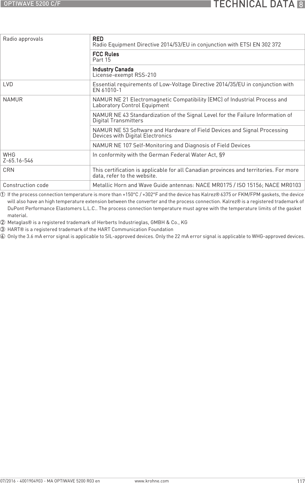
![TECHNICAL DATA 8125OPTIWAVE 5200 C/Fwww.krohne.com07/2016 - 4001904903 - MA OPTIWAVE 5200 R03 en8.5 Antenna selectionThe graphs below show which antenna to select for the application based on:•D, the measuring range,•εr, is the dielectric constant of the product being measuredFigure 8-16: Selection of antenna (graph of distance in m against εr)Figure 8-17: Selection of antenna (graph of distance in ft against εr)1 Tank height / Measuring range [m]2 Tank height / Measuring range [ft]3 εr for storage tanks with smooth product surface4 εr for process tanks without agitator or foam5 All antennas:– DN150 and DN200 Metallic Horn antenna with or without a stilling well* and PTFE and PP Wave Horn antennas– DN65/2.5¨, DN80/3¨ and DN100/4¨ Metallic Horn antenna: only for use in a stilling well*. Maximum measuring range is 10 m / 32.81 ft.– Wave Guide antenna: maximum measuring range is 6 m / 19.68 ft– DN80 and DN : maximum measuring range is 6 m / 19.68 ft6 DN150 and DN200 Metallic Horn antennas with or without a stilling well* and PTFE and PP Wave Horn antennas7 DN150/6¨ and DN200/8¨ Metallic Horn antenna with or without a stilling well*8 DN200/8¨ Metallic Horn antenna with or without a stilling well** A stilling well is equivalent to the Wave Guide antenna option or a bypass chamber](https://usermanual.wiki/KROHNE/FMCW10G52.User-Manual-EN-JH5FMCW10G52-pdf/User-Guide-4017651-Page-125.png)
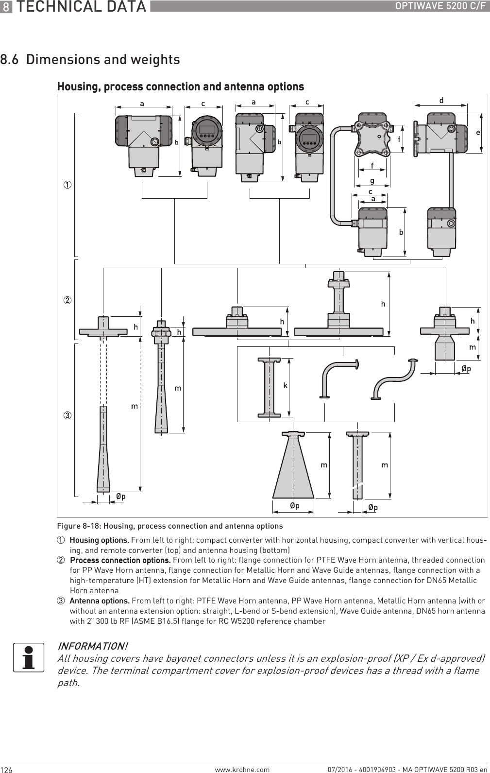
![TECHNICAL DATA 8127OPTIWAVE 5200 C/Fwww.krohne.com07/2016 - 4001904903 - MA OPTIWAVE 5200 R03 enHousing options: Dimensions in mm and inchesProcess connection and antenna options: Dimensions in mmProcess connection and antenna options: Dimensions in inchesDimensionsCompact – horizontal Compact – vertical RemoteNon-Ex or Ex i (Ex d) Non-Ex or Ex i (Ex d) Non-Ex or Ex i (Ex d)[mm] [inches] [mm] [inches] [mm] [inches]aaaa191 (258) 7.5 (10.2) 147 (210) 5.79 (8.27) 104 (104) 4.09 (4.09)bbbb214 (214) 8.43 (8.43) 258 (258) 10.16 (10.16) 181 (181) 7.13 (7.13)cccc127 (127) 5.00 (5.00) 127 (127) 5.00 (5.00) 129 (129) 5.08 (5.08)dddd————195 (195) 7.68 (7.68)eeee————146 (209) 5.75 (8.23)ffff————100 (100) 3.94 (3.94)gggg————130 (130) 5.12 (5.12)Dimensions[mm]PTFE Wave HornPP Wave HornMetallic Horn Wave GuideDN65 DN80 DN100 DN150 DN200hhhh68 33 100 (220 for the HT extension) 1kkkk— — — 100, 200, 300, 400, 500, 1000 2mmmm296 3 322 86 112 148.5 223 335 1000...6000ØpØpØpØp 43 43 65 80 100 140 200 301The HT extension is only for Metallic Horn and Wave Guide antennas. It is attached between the signal converter and the flange if the process connection temperature is +150...+250°C.2These are the length options for the straight antenna extension. For data about the dimensions of S-bend and L-bend extensions, refer to the illustrations that follow.3Other antenna lengths are available: 396, 496 or 596 mm. These options are for tanks with long nozzles.Dimensions[inches]PTFE Wave HornPP Wave HornMetallic Horn Wave Guide2.5¨3¨4¨6¨8¨hhhh2.68 1.30 3.94 (8.66 for the HT extension) 1kkkk— — — 3.94, 7.87, 11.81, 15.75, 19.68 or 39.37 2mmmm11.65 3 12.68 3.39 4.41 5.85 8.78 13.19 39.4...236.2ØpØpØpØp 1.69 1.69 2.56 3.15 3.94 5.51 7.87 1.181The HT extension is only for Metallic Horn and Wave Guide antennas. It is attached between the signal converter and the flange if the process connection temperature is +302...+482°F.2These are the length options for the straight antenna extension. For data about the dimensions of S-bend and L-bend extensions, refer to the illustrations that follow.3Other antenna lengths are available: 15.59¨, 19.53¨ or 23.46¨. These options are for tanks with long nozzles.](https://usermanual.wiki/KROHNE/FMCW10G52.User-Manual-EN-JH5FMCW10G52-pdf/User-Guide-4017651-Page-127.png)
![8 TECHNICAL DATA 128 OPTIWAVE 5200 C/Fwww.krohne.com 07/2016 - 4001904903 - MA OPTIWAVE 5200 R03 enSpecial antenna extensions: Dimensions in mmSpecial antenna extensions: Dimensions in inchesSpecial antenna extensions for tanks with obstructions (DN150 / 6¨ and DN200 / 8¨ Metallic Horn antenna options only)Figure 8-19: Special antenna extensions for tanks with obstructions (DN150 / 6¨ and DN200 / 8¨ Metallic Horn antenna options only)1 L-bend (right angle) antenna extension2 S-bend antenna extensionDimensions[mm]Metallic Horn antennaWith L-bend (right angle) extension With S-bend extensionDN150 / 6¨DN200 / 8¨DN150 / 6¨DN200 / 8¨k1k1k1k1 271 300k2k2k2k2 271 322mmmm494 606 545 657ØpØpØpØp 140 200 140 200Dimensions[inches]Metallic Horn antennaWith L-bend (right angle) extension With S-bend extensionDN150 / 6¨DN200 / 8¨DN150 / 6¨DN200 / 8¨k1k1k1k1 10.67 11.81k2k2k2k2 10.67 12.68mmmm19.45 23.86 21.46 25.87ØpØpØpØp 5.51 7.87 5.51 7.87](https://usermanual.wiki/KROHNE/FMCW10G52.User-Manual-EN-JH5FMCW10G52-pdf/User-Guide-4017651-Page-128.png)
![TECHNICAL DATA 8129OPTIWAVE 5200 C/Fwww.krohne.com07/2016 - 4001904903 - MA OPTIWAVE 5200 R03 enPurging system and heating/cooling system: Dimensions in mmPurging system and heating/cooling system: Dimensions in inchesPurging and heating/cooling system optionsFigure 8-20: Purging and heating/cooling system options1 Flange connection with purging option2 Flange connection with heating/cooling system option3 G¼ threaded connection for purging system (the plug is supplied by the manufacturer)4 G¼ threaded connection for the heating/cooling system outlet (the plug is supplied by the manufacturer)5 G¼ threaded connection for the heating/cooling system inlet (the plug is supplied by the manufacturer)Dimensions[mm]Metallic Horn antennaPurging system Heating/cooling systemDN150 / 6¨DN200 / 8¨DN150 / 6¨DN200 / 8¨mmmm223 351 202 360 1ØpØpØpØp 140 200 139.7 195qqqq34 34 53 701This is the standard length. Longer on request.Dimensions[inches]Metallic Horn antennaPurging system Heating/cooling systemDN150 / 6¨DN200 / 8¨DN150 / 6¨DN200 / 8¨mmmm8.78 13.82 8.0 14.17 1ØpØpØpØp 5.51 7.87 5.5 7.68qqqq1.34 1.34 2.1 2.761This is the standard length. Longer on request.INFORMATION!All wetted parts (flange, antenna and heating/cooling jacket) of the heating/cooling system option are made of 316L / 1.4404.](https://usermanual.wiki/KROHNE/FMCW10G52.User-Manual-EN-JH5FMCW10G52-pdf/User-Guide-4017651-Page-129.png)
![8 TECHNICAL DATA 130 OPTIWAVE 5200 C/Fwww.krohne.com 07/2016 - 4001904903 - MA OPTIWAVE 5200 R03 enDimensions and weights in mm and kgDimensions and weights in inches and lbWeather protection option (vertical signal converters – for the compact version only)Figure 8-21: Weather protection option for vertical signal converter versions (compact version only)1 Non-Ex / Ex i / IS: Rear view (with weather protection closed)2 Non-Ex / Ex i / IS: Right side (with weather protection closed)3 Non-Ex / Ex i / IS: Front view (with weather protection closed)4 Ex d / XP: Rear view (with weather protection closed)5 Ex d / XP: Right side (with weather protection closed)6 Ex d / XP: Front view (with weather protection closed)Weather protection Version Dimensions [mm] Weights [kg]a b c dVertical signal converter Non-Ex / Ex i / IS 277 120 96 77 1.3Ex d / XP 277 120 166 77 1.5Weather protection Version Dimensions [mm] Weights [kg]a b c dVertical signal converter Non-Ex / Ex i / IS 10.9 4.7 3.8 3.0 2.9Ex d / XP 10.9 4.7 6.5 3.0 3.3](https://usermanual.wiki/KROHNE/FMCW10G52.User-Manual-EN-JH5FMCW10G52-pdf/User-Guide-4017651-Page-130.png)
![TECHNICAL DATA 8131OPTIWAVE 5200 C/Fwww.krohne.com07/2016 - 4001904903 - MA OPTIWAVE 5200 R03 enDimensions and weights in mm and kgDimensions and weights in inches and lbWeather protection option (horizontal signal converters – for the compact version only)Figure 8-22: Weather protection option for horizontal signal converter versions (compact version only)1 Non-Ex / Ex i / IS: Front view (with weather protection closed)2 Non-Ex / Ex i / IS: Left side (with weather protection closed)3 Non-Ex / Ex i / IS: Rear view (with weather protection closed)4 Ex d / XP: Front view (with weather protection closed)5 Ex d / XP: Left side (with weather protection closed)6 Ex d / XP: Rear view (with weather protection closed)Weather protection Version Dimensions [mm] Weights [kg]a b c dHorizontal signal converter Non-Ex / Ex i / IS 279 120 96 77 1.3Ex d / XP 279 120 166 77 1.5Weather protection Version Dimensions [inches] Weights [lb]a b c dHorizontal signal converter Non-Ex / Ex i / IS 11.0 4.7 3.8 3.0 2.9Ex d / XP 11.0 4.7 6.5 3.0 3.3](https://usermanual.wiki/KROHNE/FMCW10G52.User-Manual-EN-JH5FMCW10G52-pdf/User-Guide-4017651-Page-131.png)
![8 TECHNICAL DATA 132 OPTIWAVE 5200 C/Fwww.krohne.com 07/2016 - 4001904903 - MA OPTIWAVE 5200 R03 enDimensions and weights in mm and kgDimensions and weights in inches and lbWeather protection option (antenna housing – for the remote version only)Figure 8-23: Weather protection option for the antenna housing (remote converter version only)1 Front view (with weather protection closed)2 Left side (with weather protection closed)3 Rear view (with weather protection closed)Weather protection Dimensions [mm] Weights [kg]a b c dAntenna housing 204 120 96 77 1.3Weather protection Dimensions [inches] Weights [lb]a b c dAntenna housing 8.0 4.7 3.8 3.0 2.9](https://usermanual.wiki/KROHNE/FMCW10G52.User-Manual-EN-JH5FMCW10G52-pdf/User-Guide-4017651-Page-132.png)
![TECHNICAL DATA 8133OPTIWAVE 5200 C/Fwww.krohne.com07/2016 - 4001904903 - MA OPTIWAVE 5200 R03 enConverter and antenna housing weightsAntenna option weightsType of housing WeightsAluminium housing Stainless steel housing[kg] [lb] [kg] [lb]Non-Ex / intrinsically-safe (Ex i / IS)Non-Ex / intrinsically-safe (Ex i / IS)Non-Ex / intrinsically-safe (Ex i / IS)Non-Ex / intrinsically-safe (Ex i / IS)Compact converter 3.0 6.6 6.6 14.6Remote converter 1 2.5 5.5 5.9 13.0Antenna housing 1 2.0 4.4 4.1 9.0Explosion proof (Ex d / XP)Explosion proof (Ex d / XP)Explosion proof (Ex d / XP)Explosion proof (Ex d / XP)Compact converter 3.2 7.1 7.5 16.5Remote converter 1 2.9 6.40 7.1 15.65Antenna housing 1 2.0 4.4 4.1 9.01The remote version of the device has a "remote converter" and an "antenna housing". For more data, refer to "Housing dimensions" at the start of this section.Antenna options Min./Max. weights[kg] [lb]Standard options, without converterStandard options, without converterStandard options, without converterStandard options, without converterPTFE Wave Horn antenna with flange connection 3.7 8.2PTFE Wave Horn antenna with flange connection, with 100 mm / 3.94¨ antenna extension 3.78 8.3PTFE Wave Horn antenna with flange connection, with 200 mm / 7.87¨ antenna extension 3.86 8.5PTFE Wave Horn antenna with flange connection, with 300 mm / 11.81¨ antenna extension 3.94 8.7PP Wave Horn antenna with threaded connection 0.7 1.5DN65 / 2.5¨ Metallic Horn antenna with flange connection – only for the RC W5200 reference chamber5.35 11.8DN80 / 3¨ Metallic Horn antenna with flange connection, standard length 5.6...37.1 12.3...81.8DN100 / 4¨ Metallic Horn antenna with flange connection, standard length 9.1...37.2 20.1...82DN150 / 6¨ Metallic Horn antenna with flange connection, standard length 13.6...37.5 30...82.7DN200 / 8¨ Metallic Horn antenna with flange connection, standard length 14.0..37.8 30.9...83.3Wave Guide antenna with flange connection, 1...6 m / 3.28...19.68 ft 1.6...9.9 3.5...21.8Antenna extension optionsAntenna extension optionsAntenna extension optionsAntenna extension optionsStraight extension, length 100 mm / 3.94¨ 1 +0.76 +1.68Straight extension, length 200 mm / 7.87¨ 1 +0.94 +2.07Straight extension, length 300 mm / 11.81¨ 1 +1.12 +2.47Straight extension, length 400 mm / 15.75¨ 1 +1.30 +2.87Straight extension, length 500 mm / 19.69¨ 1 +1.48 +3.26Straight extension, length 1000 mm / 39.37¨ 1 +2.38 +5.25S-bend extension 1 +1.56 +3.44L-bend (right-angle) extension 1 +1.48 +3.26](https://usermanual.wiki/KROHNE/FMCW10G52.User-Manual-EN-JH5FMCW10G52-pdf/User-Guide-4017651-Page-133.png)
![8 TECHNICAL DATA 134 OPTIWAVE 5200 C/Fwww.krohne.com 07/2016 - 4001904903 - MA OPTIWAVE 5200 R03 enOther optionsOther optionsOther optionsOther optionsHT extension 2 +0.98 +2.161This option is for Metallic Horn and Wave Guide antenna options2This component is only for the Metallic Horn and Wave Guide antennas. It is attached between the signal converter and the flange if the process connection temperature is +150...+250°C / +302...+482°F.Antenna options Min./Max. weights[kg] [lb]](https://usermanual.wiki/KROHNE/FMCW10G52.User-Manual-EN-JH5FMCW10G52-pdf/User-Guide-4017651-Page-134.png)
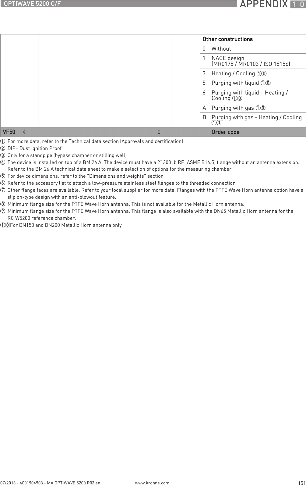
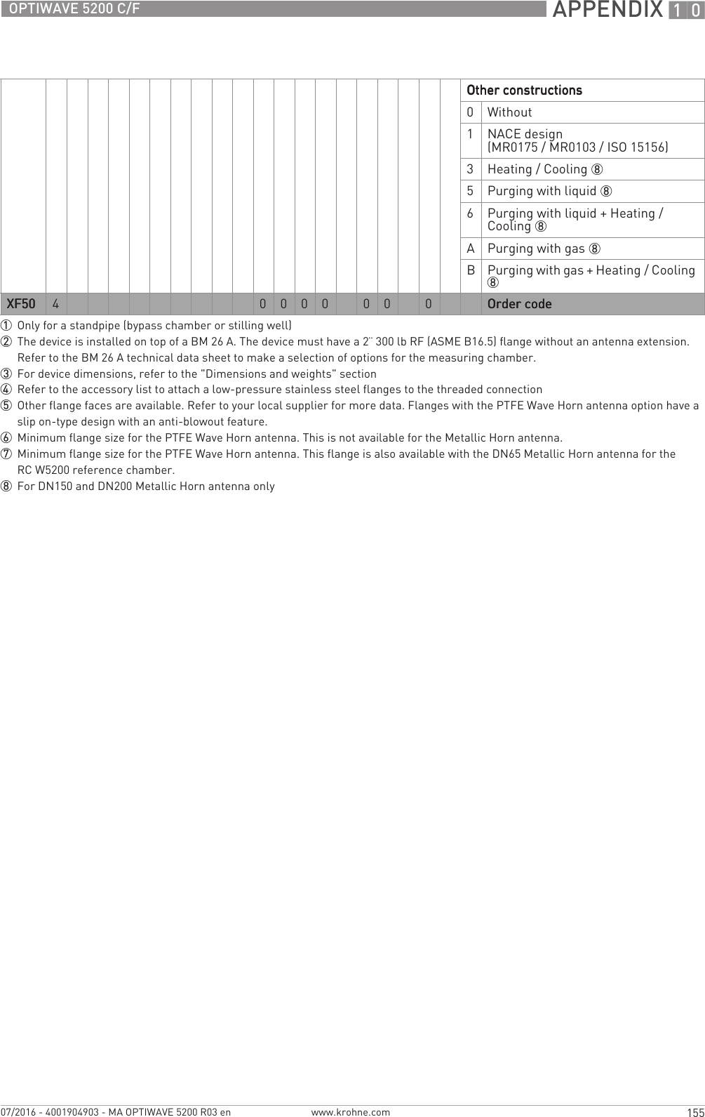
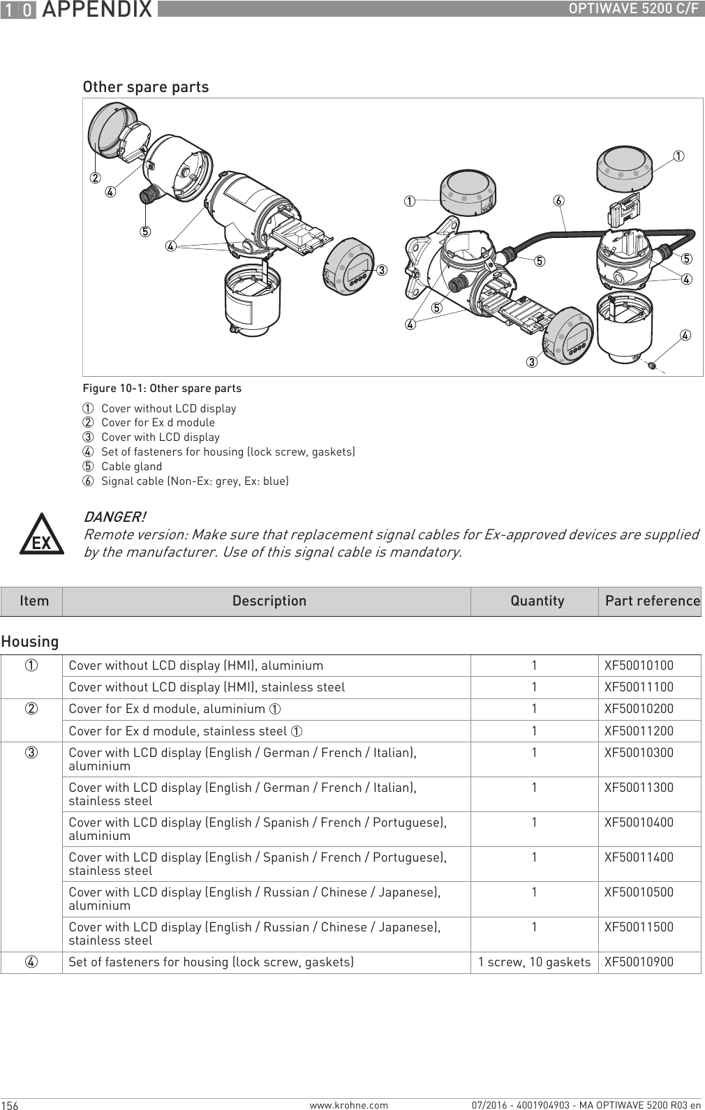
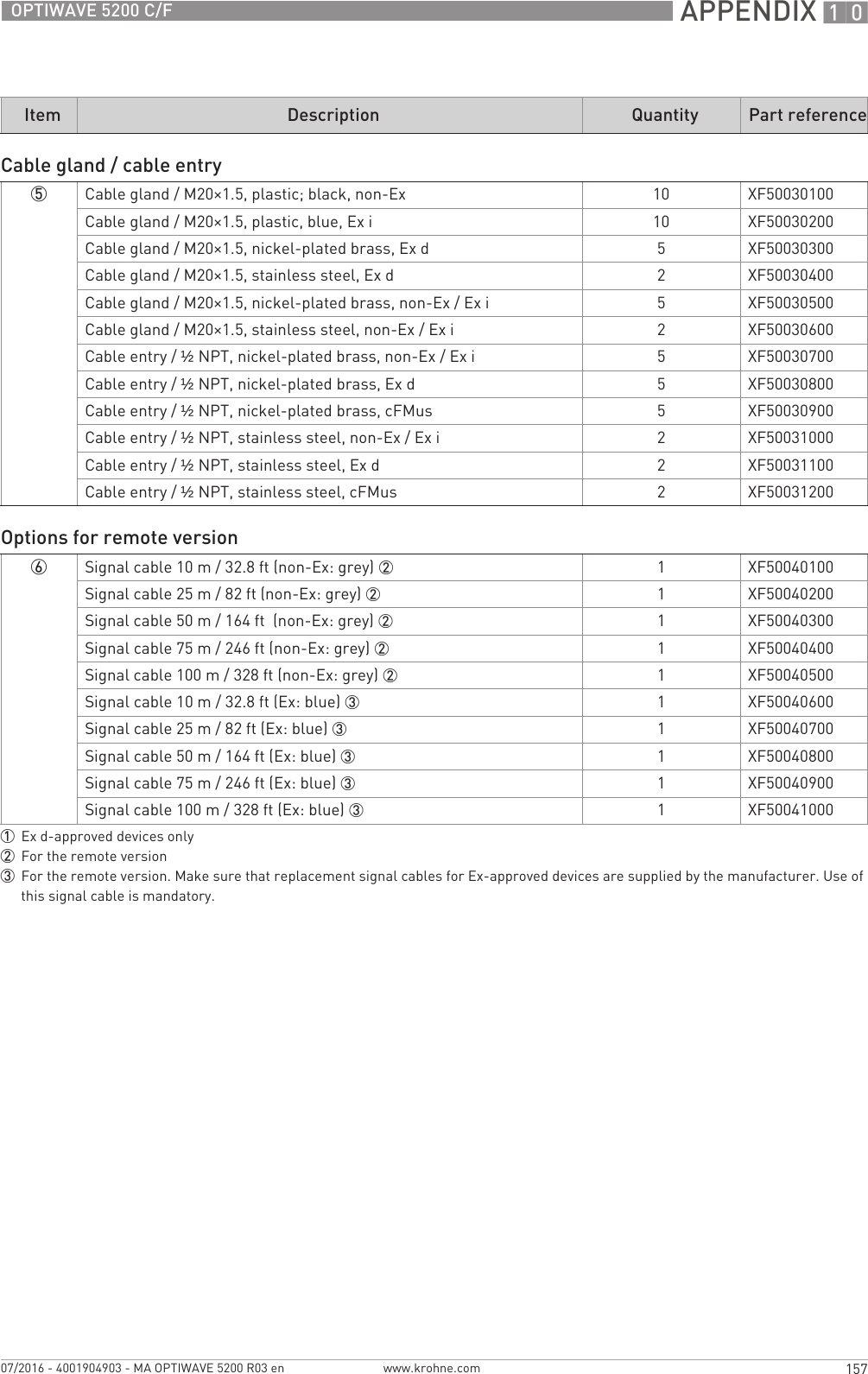
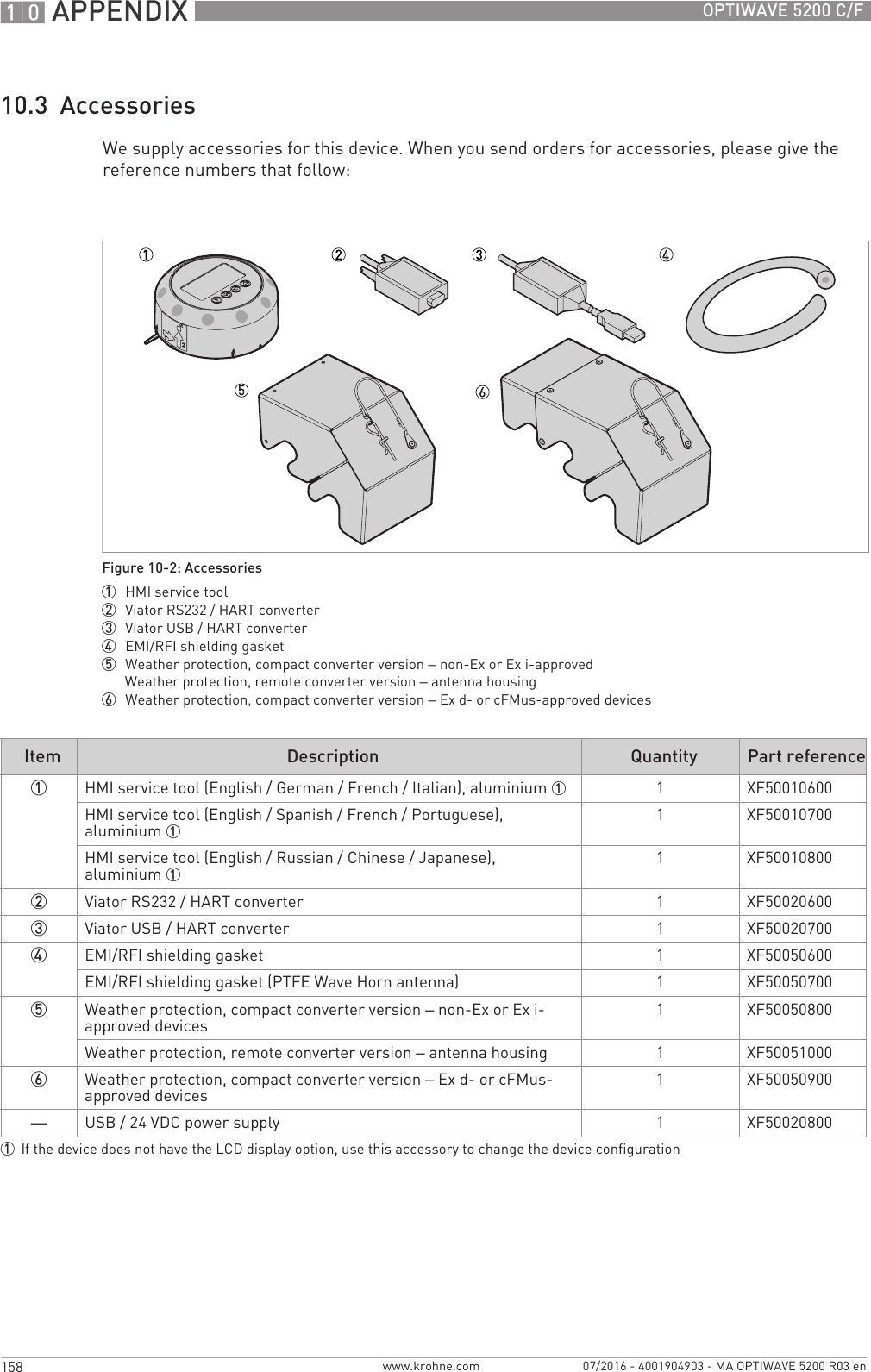
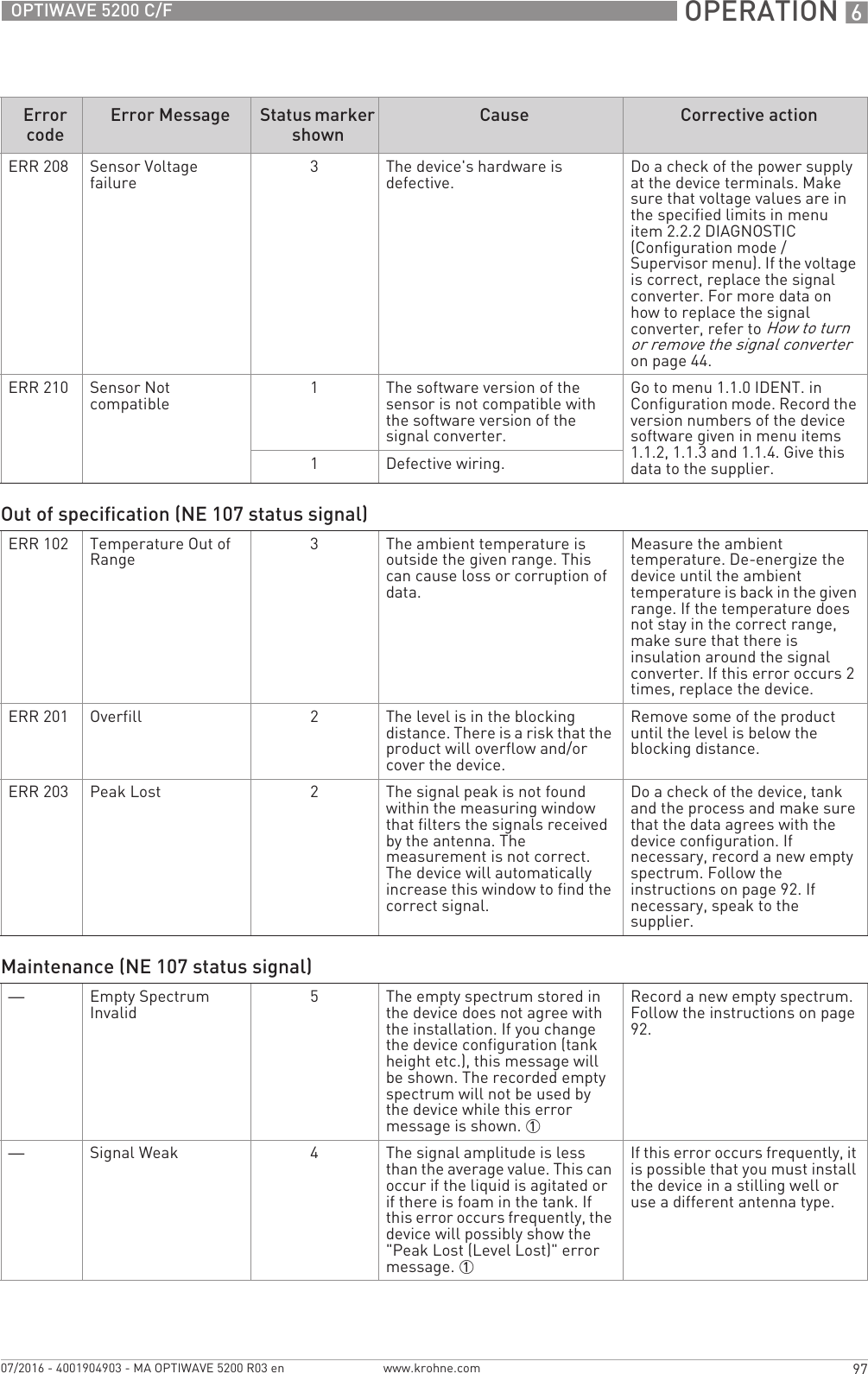
![10 APPENDIX 146 OPTIWAVE 5200 C/Fwww.krohne.com 07/2016 - 4001904903 - MA OPTIWAVE 5200 R03 en10.1 Order codeMake a selection from each column to get the full order code. The characters of the order code highlighted in light grey describe the standard.VF50 4OPTIWAVE 5200 C/F 10 GHz Radar (FMCW) Level Transmitter for liquids in storage and process applicationsOPTIWAVE 5200 C/F 10 GHz Radar (FMCW) Level Transmitter for liquids in storage and process applicationsOPTIWAVE 5200 C/F 10 GHz Radar (FMCW) Level Transmitter for liquids in storage and process applicationsOPTIWAVE 5200 C/F 10 GHz Radar (FMCW) Level Transmitter for liquids in storage and process applicationsConverter version (Housing material Converter version (Housing material Converter version (Housing material Converter version (Housing material – protection category) protection category) protection category) protection category)1OPTIWAVE 5200 C: Compact version (Aluminium – IP66/67)2OPTIWAVE 5200 C: Compact version (Stainless steel – IP66/67)3OPTIWAVE 5200 F: Remote version (converter & antenna housing: Aluminium – IP66/67)4OPTIWAVE 5200 F: Remote version (converter & antenna housing: Stainless steel – IP66/67)ApprovalApprovalApprovalApproval 10Without1ATEX II 1/2 G Ex ia IIC T6 Ga/Gb + II 1/2 D Ex ia IIIC Da/Db2ATEX II 1/2 G Ex d ia IIC T6 Ga/Gb + II 1/2 D Ex ia tb IIIC Da/Db4ATEX II 3 G Ex ic IIC T6 Gc + II 3 D Ex ic IIIC Dc (Zone 2 & 22)6IECEx Ex ia IIC T6 Ga/Gb + Ex ia IIIC Da/Db7IECEx Ex d ia IIC T6 Ga/Gb + Ex ia tb IIIC Da/Db8IECEx Ex ic IIC T6 Gc + Ex ic IIIC Dc (Zone 2 & 22)AcFMus IS CL I/II/III DIV 1 GPS A-G + CL I zone 0/20 Ex ia IIC/IIIC T6BcFMus XP-AIS/DIP CL I/II/III DIV 1 GPS A-G (A not for Canada) + CL I zone 0/20 Ex d[ia]/tb[ia] IIC/IIIC T6 2CcFMus NI CL I/II/III DIV 2 GPS A-G + CL I zone 2 Ex nA IIC T6LNEPSI Ex ia IIC T6 Ga/Gb + DIP A20/A21 2MNEPSI Ex d ia IIC T6 Ga/Gb + DIP A20/A21 2RINMETRO Ex ia IIC T6 Ga/Gb + Ex ia IIIC Da/DbSINMETRO Ex d ia IIC T6 Ga/Gb + Ex ia tb IIIC Da/DbTINMETRO Ex ic IIC T6 Gc + Ex ic IIIC Dc (Zone 2 & 22)Other approvalOther approvalOther approvalOther approval0Without1SIL 2 – only available for the OPTIWAVE 5200 C (compact version) with a 4…20 mA output4CRN (Canadian Registration Number)5CRN + SIL 2 – only available for the OPTIWAVE 5200 C (compact version) with a 4…20 mA outputAWHG – must be supplied with a calibration certificateBEAC RussiaCEAC BelarusDEAC Russia + SIL 2 – only available for the OPTIWAVE 5200 C (compact version) with a 4…20 mA outputEEAC Belarus + SIL 2 – only available for the OPTIWAVE 5200 C (compact version) with a 4…20 mA outputKEAC KazakhstanLEAC Kazakhstan + SIL 2 – only available for the OPTIWAVE 5200 C (compact version) with a 4…20 mA outputVF50VF50VF50VF50 4Order code (complete this code on the pages that follow)Order code (complete this code on the pages that follow)Order code (complete this code on the pages that follow)Order code (complete this code on the pages that follow)](https://usermanual.wiki/KROHNE/FMCW10G52.User-Manual-EN-JH5FMCW10G52-pdf/User-Guide-4017651-Page-146.png)