KROHNE FMCW10G52 Tank Level Probing Radar User Manual HB OPTIWAVE5200 en 120321 4001904901 R01
KROHNE Tank Level Probing Radar HB OPTIWAVE5200 en 120321 4001904901 R01
KROHNE >
Contents
- 1. User Manual
- 2. User Manual EN - JH5FMCW10G52.pdf
User Manual

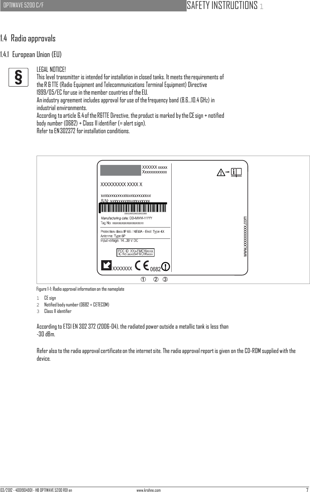
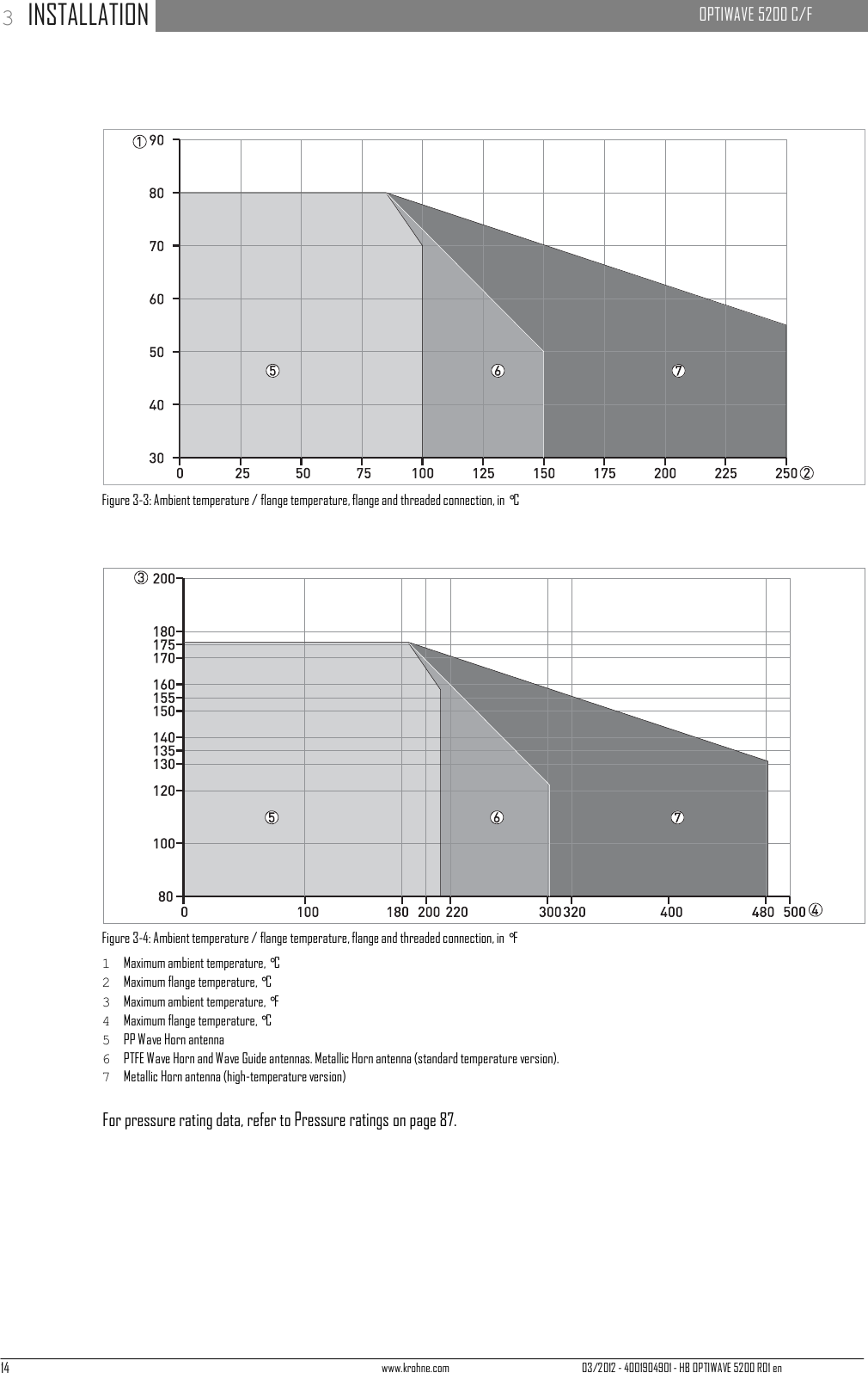
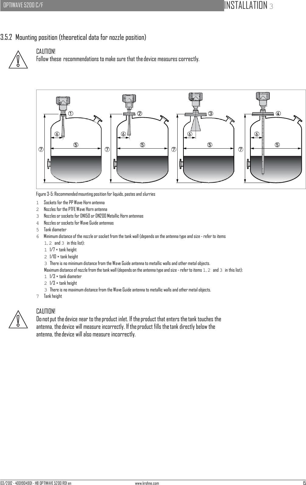
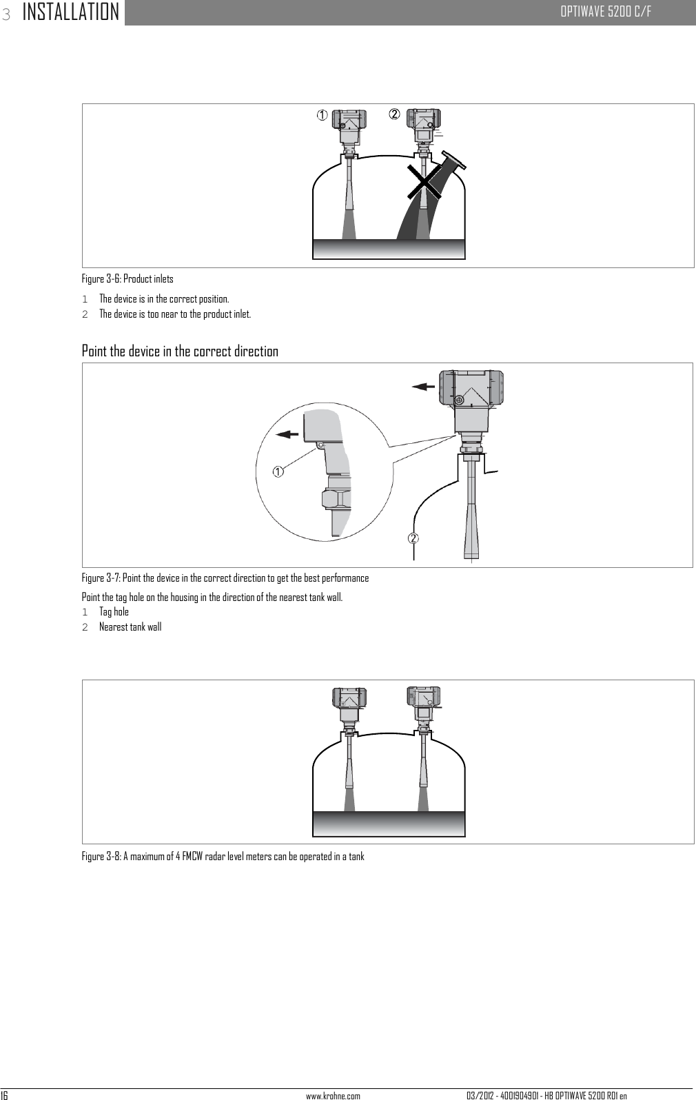
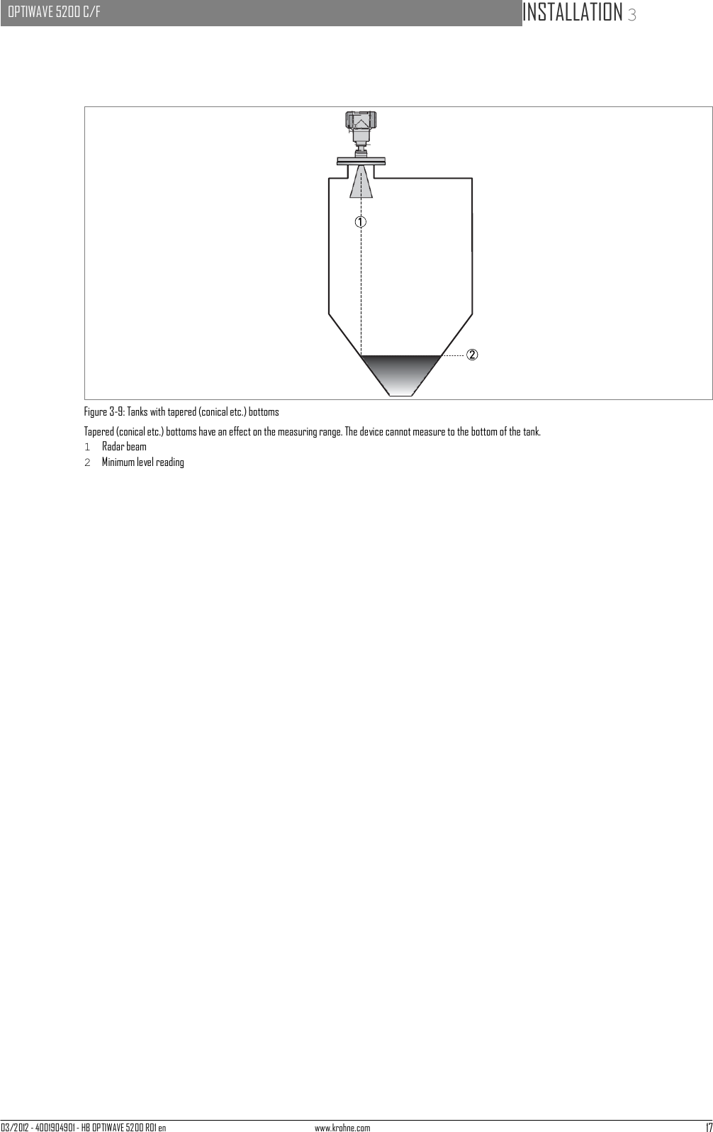
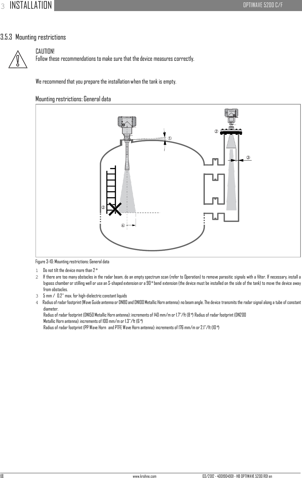
![03/2012 - 4001904901 - HB OPTIWAVE 5200 R01 en www.krohne.com 13 OPTIWAVE 5200 C/F INSTALLATION 3 3.5 Installation 3.5.1 Pressure and temperature ranges Figure 3-2: Pressure and temperature ranges 1 Flange temperature Non-Ex devices: Depends on the type of antenna, process connection and the seal material. Refer to the table that fol- lows. Ex devices: see supplementary operating instructions 2 Ambient temperature for operation of the display -20...+60°C / -4...+140°F If the ambient temperature is not between these limits, the display screen switches off automatically. The device con- tinues to operate. 3 Ambient temperature Non-Ex devices: -40...+80°C / -40...+176°F Ex devices: see supplementary operating instructions 4 Process pressure Depends on the type of antenna and process connection. Refer to the table that follows. Antenna type Process connection Seal Process connection temperature Process pressure [°C] [°F] [barg] [psig] PP Wave Horn G 1½; 1½ NPT - -20...+100 -4...+212 -1...16 1 -14.5...232 1 PTFE Wave Horn Flange with PTFE plate - -50...+150 -58...+302 -1...34 1 -14.5...493 1 Metallic Horn Wave Guide Flange Metaglas® with FKM/FPM -40...+200 -40...+392 -1...40 1 -14.5...580 1 Metaglas® with Kalrez® 6375 -20...+250 -4...+482 -1...40 1 -14.5...580 1 Metaglas® with PFA -60...+150 -76...+302 -1...40 1 -14.5...580 1 Metaglas® with EPDM -50...+130 -58...+266 -1...40 1 -14.5...580 1 1 Higher pressures on request](https://usermanual.wiki/KROHNE/FMCW10G52.User-Manual/User-Guide-1893999-Page-13.png)

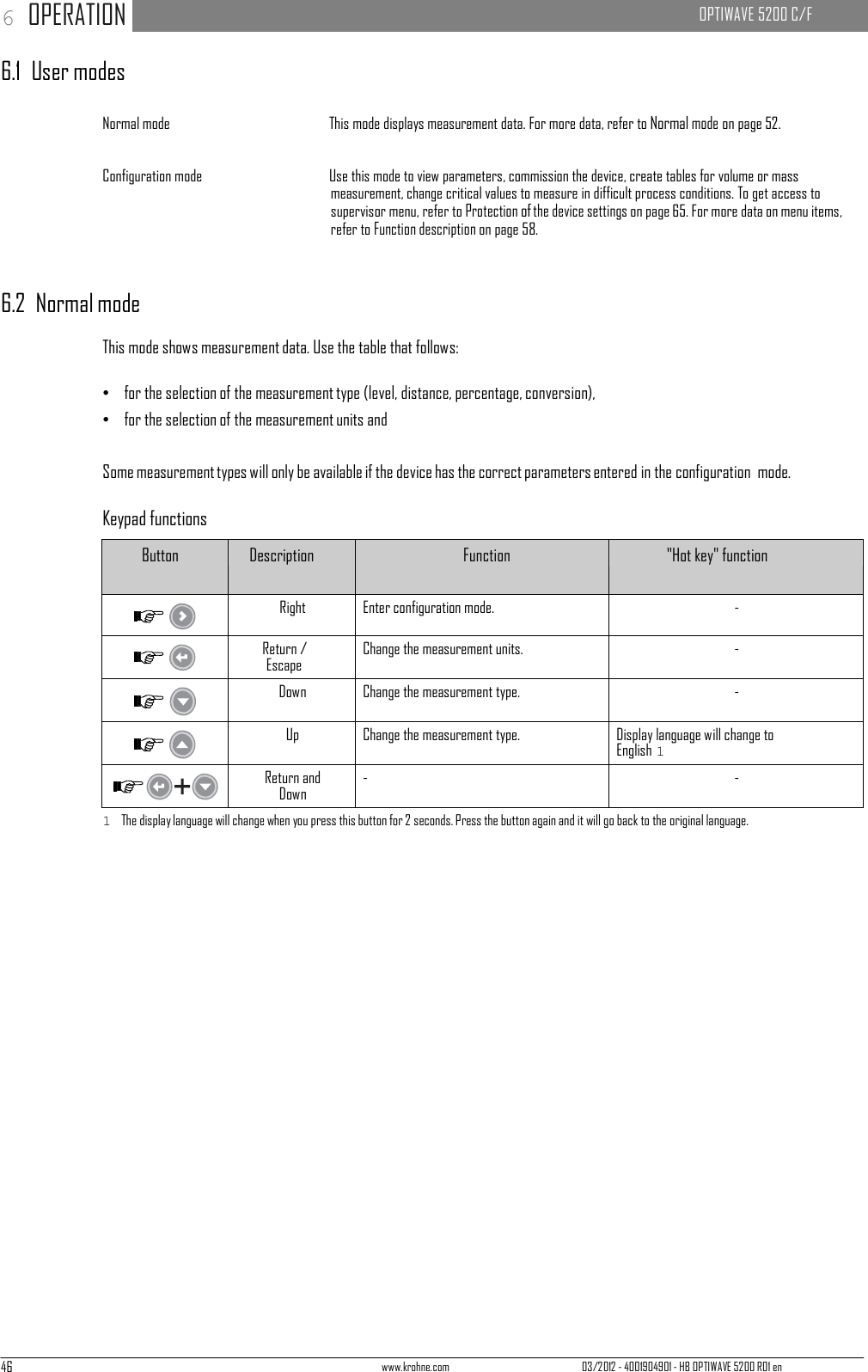
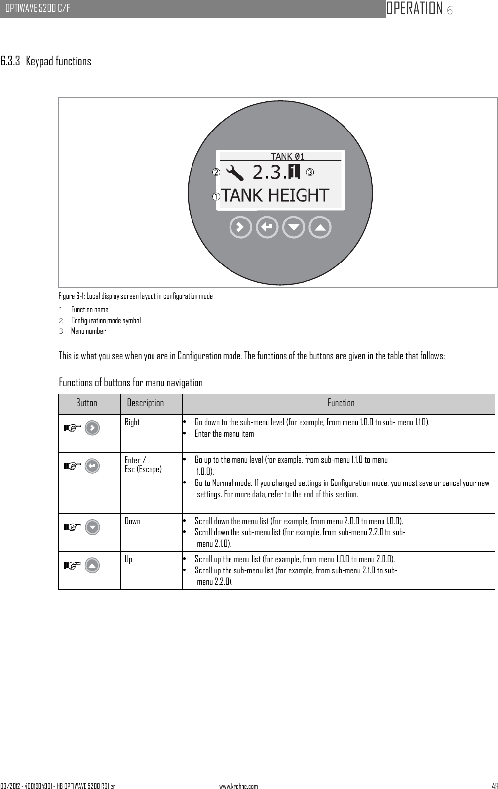
![03/2012 - 4001904901 - HB OPTIWAVE 5200 R01 en www.krohne.com 45 OPTIWAVE 5200 C/F OPERATION 6 Figure 5-2: Local display screen layout in configuration mode 1 Function name 2 Configuration mode symbol 3 Menu number 5.3.2 Keypad buttons Keypad button Function [Right] Readings: Enter Commissioning menu (Enter Configuration mode) [Return / Escape] Readings: Change units (m, cm, mm, in, ft) Configuration mode: Exit [Down] Readings: Change measurement type (distance, level , output (%), output (mA)) Configuration mode: Decrease value or change parameter [Up] Readings: Change measurement type (distance, level , output (%), output (mA)) Configuration mode: Increase value or change parameter For data on keypad functions, refer to Normal mode on page 52.](https://usermanual.wiki/KROHNE/FMCW10G52.User-Manual/User-Guide-1893999-Page-45.png)
![48 www.krohne.com 03/2012 - 4001904901 - HB OPTIWAVE 5200 R01 en 6 OPERATION OPTIWAVE 5200 C/F 6.3.2 How to get access to the commissioning menu Do the steps that follow: • Press the [>] button. i This shows the Information menu. The Information menu is read only and does not have password security. • Press the [ ] button one time to scroll up to the Supervisor menu. i The screen shows the text "2.0.0 SUPERVISOR". • Press the [>] button one time. i The screen shows a line. You must enter the password. Press the buttons under the display screen 6 times (in total and in a given order) to to get access to Configuration mode. • Type in the password. The factory-set password is [>], [^], [ ], [ ], [>] and [^]. i The device shows the text "2.1.0 COMMISSION.". Make a selection from the items in the supervisor menu. CAUTION! SIL-approved devices: For data about critical device parameters for SIL approval, refer to the Safety Manual (SIL approval). INFORMATION! How to set the supervisor password to "on" or "off" The supervisor password is set to "on" by default. If it is necessary to set this function to "off", refer to Function description on page 58, Table 2: Supervisor menu, menu item PSWD YES/NO (2.7.4). INFORMATION! How to change the supervisor password You can change the password for the supervisor menu. For more data, refer to Function description on page 58, Table 2: Supervisor menu, menu item PASSWORD (2.7.5).](https://usermanual.wiki/KROHNE/FMCW10G52.User-Manual/User-Guide-1893999-Page-48.png)
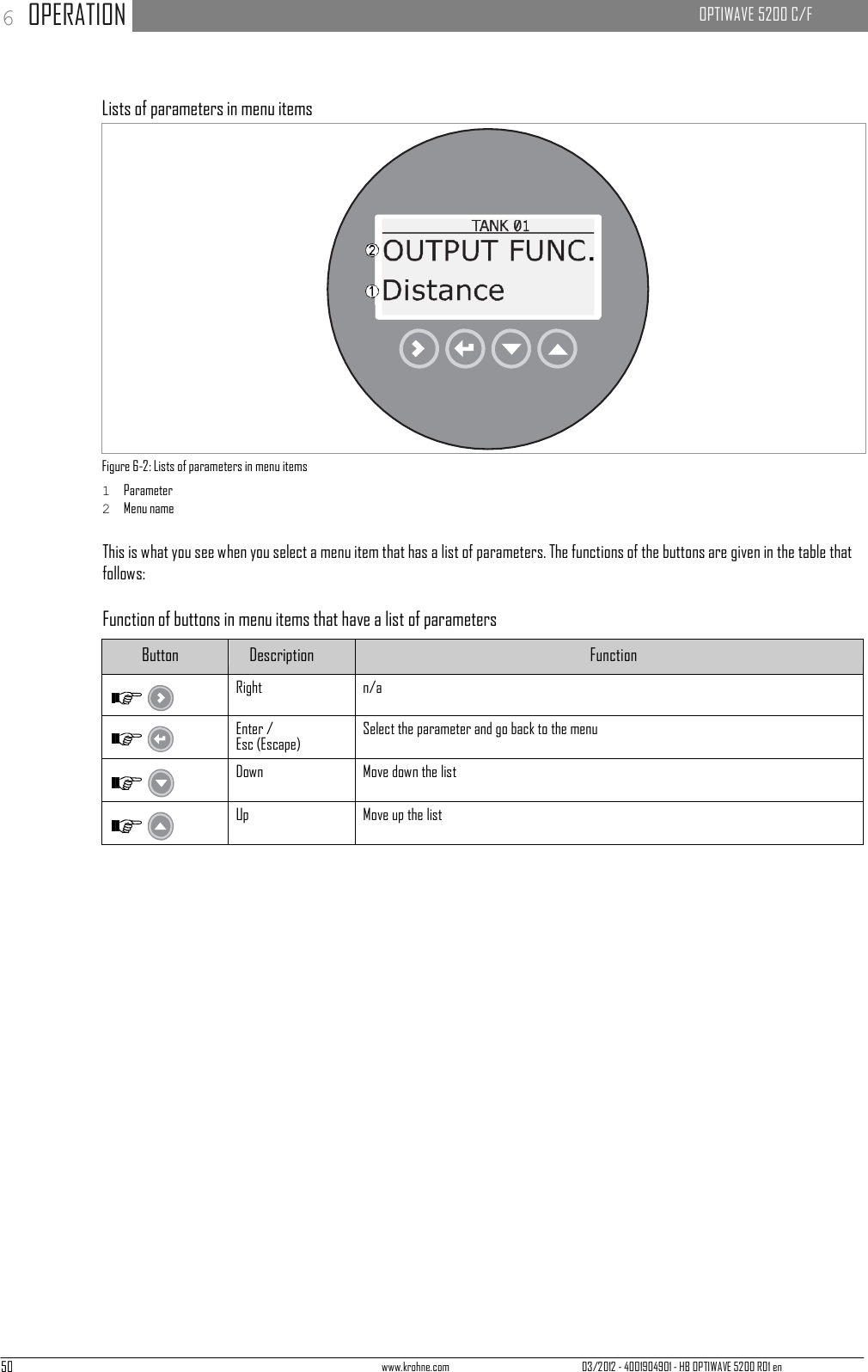
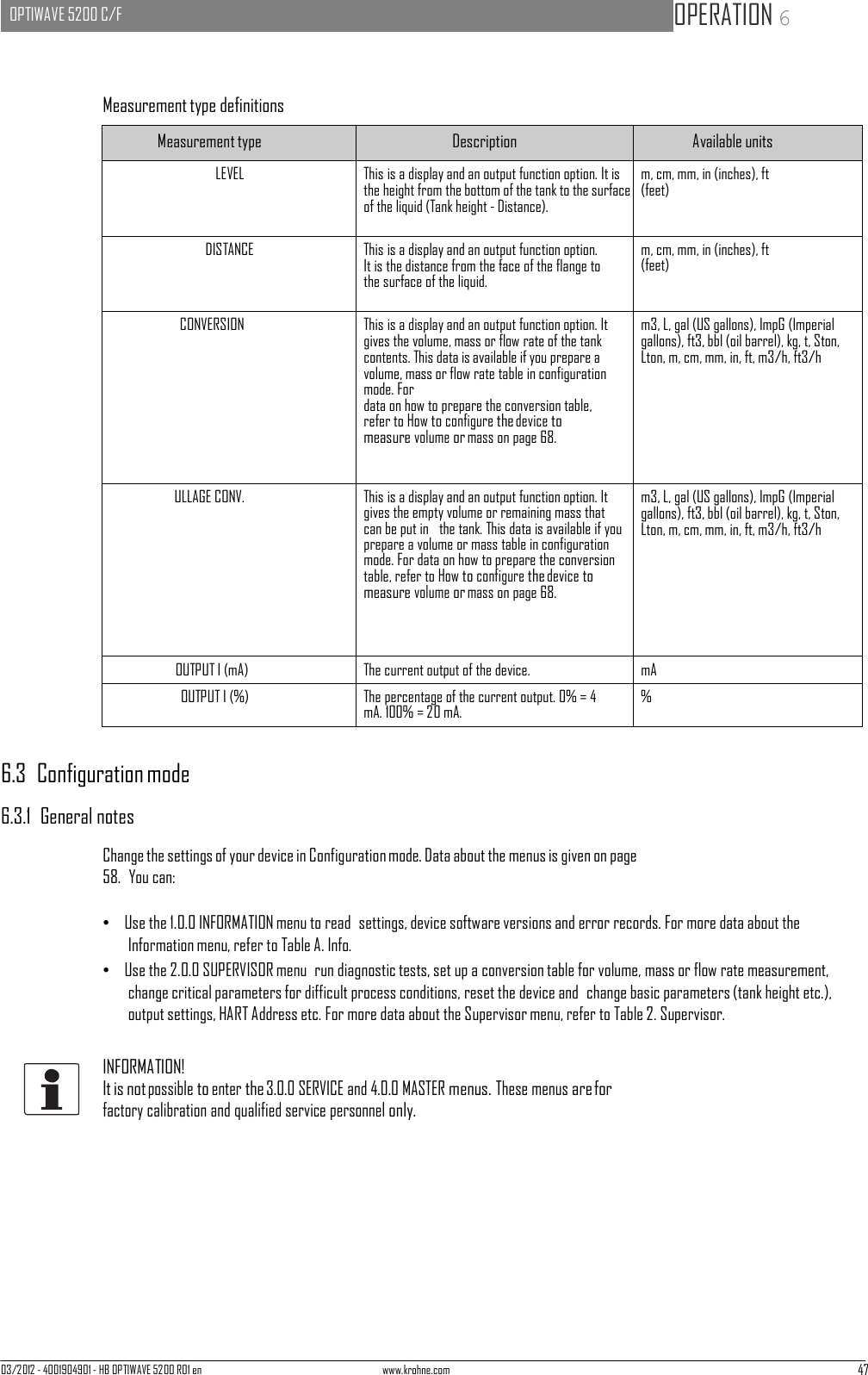
![03/2012 - 4001904901 - HB OPTIWAVE 5200 R01 en www.krohne.com 51 OPTIWAVE 5200 C/F OPERATION 6 Values in menu items Figure 6-3: Values in menu items 1 Menu item with values stored at this time (first screen) 2 Press [>] again to change the values. A cursor shows on the first digit. 3 Menu item name 4 Cursor on the selected digit This is what you see when you select a menu item that has a value. The functions of the buttons are given in the table that follows: Function of buttons in menu items that have values Button Description Function Right • Enter the menu item and see the value stored at this time. • Enter the menu item configuration level to change the value. • Move the cursor to the next digit on the right. If the cursor is on the last digit, press [>] again to go back to the first digit. Enter / Esc (Escape) Accept the value and go back to the sub-menu. Down Decrease the digit value. Up Increase the digit value. How to save settings changed in the supervisor menu (menu 2.0.0) • When you have changed parameters in all the necessary menu items, press [^] to accept the new parameter. • Press [^] to go back to the "STORE" screen. • The device will ask you to save or cancel your settings. Press [ ] or [ ] to select STORE YES or STORE NO. Press [^] to accept or reject the new settings. i The display goes back to Normal mode.](https://usermanual.wiki/KROHNE/FMCW10G52.User-Manual/User-Guide-1893999-Page-51.png)
![03/2012 - 4001904901 - HB OPTIWAVE 5200 R01 en www.krohne.com 53 OPTIWAVE 5200 C/F OPERATION 6 Menu No. Function Function description Selection list Default 1.3.0 HISTORY 1.3.1 ERROR RECORD A log of device errors. Press [>] to read the errors. Press [ ] or [ ] to scroll up or down the list. Each error is identified by a code. Press > again to show the number of incidents and the time since the last incident in days, hours, minutes and seconds. For more data on errors,. Read only. 2. Supervisor menu Menu No. Function Function description Selection list Default 2.0.0 SUPERVISOR The supervisor can use this menu to change parameters. 2.1.0 COMMISSION. 2.1.1 PARAMETERS This starts a quick set-up procedure applicable to most applications. The supervisor can give the tank height (TANK HEIGHT), type of tank (TANK TYPE), output function (OUTPU FUNC.), current output range (RANGE I), 4 mA setting (SCALE 4mA), 20 mA setting (SCALE 20mA), error delay (ERROR DELAY) and tag name (TAG NAME). 2.1.2 EMP.SPEC.REC. Fixed and moving objects in the tank cause interference signals. Put them through this filter to correctly measure the tank contents. A quick set-up procedure will go through the steps that follow: 1 Do you have a completely filled tank? If the tank is full, it is not possible to complete this procedure. The tank must be partially filled or empty. Yes [>], No [ ] 2 Please, activate moving parts! We recommend that you switch on moving equipment to filter all interference signals. OK [>] 3 IIs your tank partially filled or empty? If the tank is partially filled, the device must include the tank contents when it filters the signal. Partially [>], Empty [ ] 4 MEAS.DISTANCE If the tank is partially filled, type in a distance shorter than that between the flange and the tank contents. min-max: 0…tank height (2.3.1) ?](https://usermanual.wiki/KROHNE/FMCW10G52.User-Manual/User-Guide-1893999-Page-53.png)
![54 www.krohne.com 03/2012 - 4001904901 - HB OPTIWAVE 5200 R01 en 6 OPERATION OPTIWAVE 5200 C/F Menu No. Function Function description Selection list Default 5 Emp.Spec.Type Use the average value for tanks which contain fixed objects only. Use the maximum value for tanks which contain many objects or moving objects. Maximum, Average ? 6 Recording in progress Reading in progress 7 Empty spectrum graph Push [>] to make a selection from the available spectra to get the correct level signal, if the tank is partially filled. 8 Do you want to save the spectrum? Yes [>], No [ ] 2.2.0 TESTS The device serial number. 2.2.1 SET OUTPUT This sets the current output to a test value [mA]. The output will change to the given value, independent of the measured value. The current output will go back to the measured value when the display goes back to the menu level. 3.5, 4, 6, 8, 10, 12, 14, 16, 18, 20 or 22 mA 3.5 mA 2.2.2 DIAGNOSTIC This starts the hardware test. Press [>] many times to show: the time of operation (D1), temperature of the electronic converter board (T1), loop current (I1), load current (I2), voltage 5.6 V (V1), voltage on capacitors (V2), voltage 3.3 V (V3), reset counter (C1). If you press [>] again, the display goes back to the menu level. 2.3.0 BASIC PARAM. The basic parameters for configuration of the device. 2.3.1 TANK HEIGHT The distance from the flange face / thread stop of the tank connection down to the tank bottom. min-max: 0…30 m / 0…98.4 ft 10.0 m / 32.8 ft 2.3.2 BLOCK. DIST. Blocking distance. The distance from the flange to the top limit of the measuring range (a zone given by the user where it is not possible to measure). We recommend a blocking distance of 500 mm / 19.7¨ below the antenna. If the distance is less than the blocking distance, the device continues to display the blocking distance. min: 100 mm / 13.9¨ or 2.3.6 ANTENNA.EXT max: 2.3.1 TANK HEIGHT 500 mm / 19.7¨ 2.3.3 TIME CONST. Using this function, the device processes several measurement readings to filter out disturbances. Increasing the time constant will smoothen the integrated readings, decreasing will roughen the readings. s=seconds. min-max: 1.00...100.00 s 10.00 s](https://usermanual.wiki/KROHNE/FMCW10G52.User-Manual/User-Guide-1893999-Page-54.png)
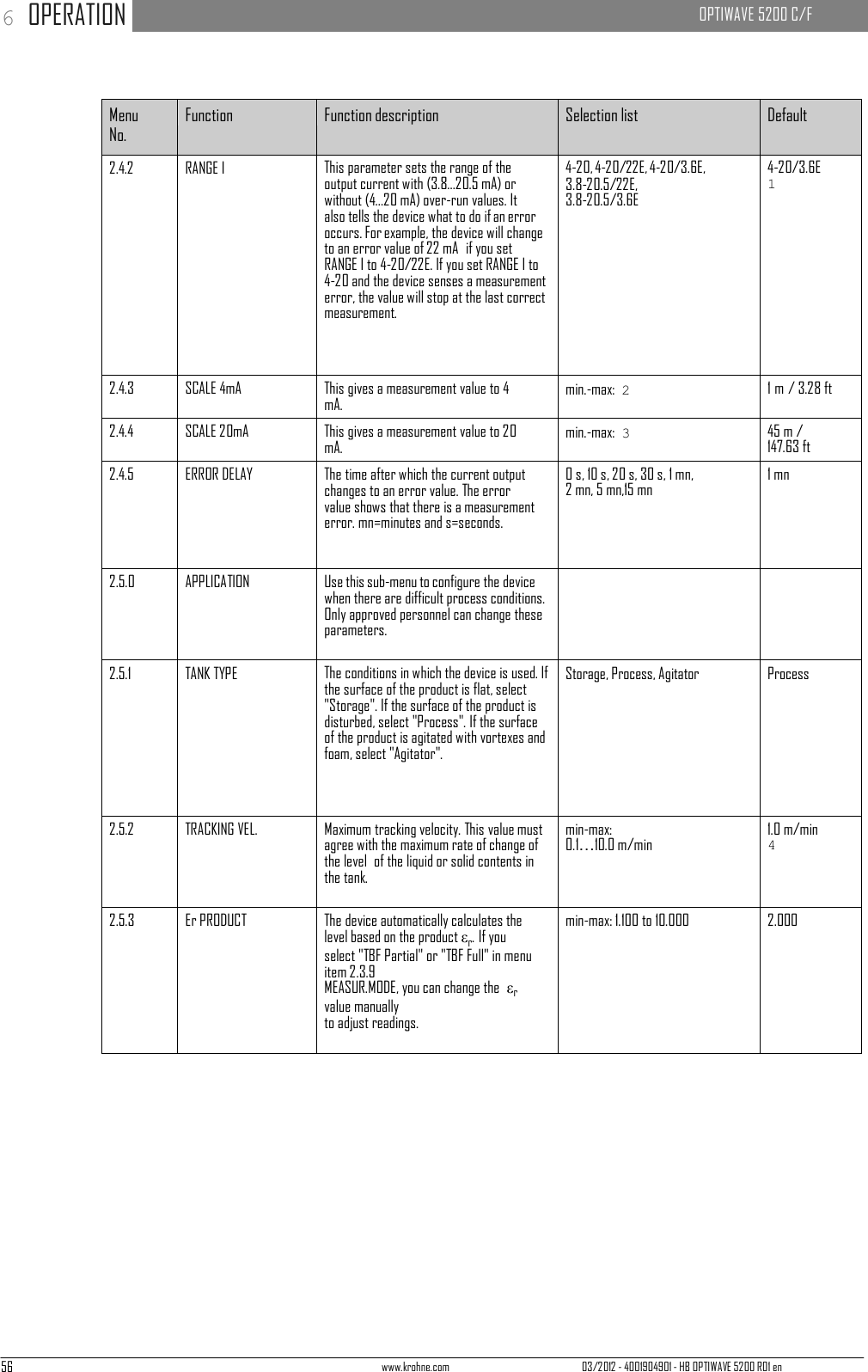
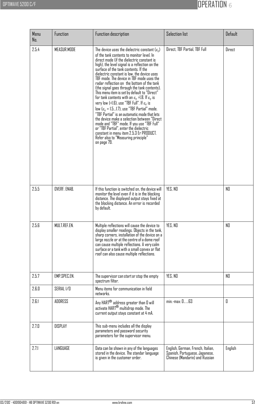
![58 www.krohne.com 03/2012 - 4001904901 - HB OPTIWAVE 5200 R01 en 6 OPERATION OPTIWAVE 5200 C/F Menu No. Function Function description Selection list Default 2.7.2 LENGTH UNIT The length unit shown in normal mode. m, cm, mm, in (inches), ft (feet) m 2.7.3 CONV UNIT Conversion unit. The length, volume, mass or flow rate conversion unit for the conversion table and shown in normal mode. m3, L, gal (US gallons), ImpG (Imperial gallons), ft3, bbl (oil barrel), kg, t, Ston, Lton, m, cm, mm, in, ft, m3/h, ft3/h L 2.7.4 PSWD YES/NO If it is necessary to protect your settings in the supervisor menu with a password, set this menu item to "YES". YES, NO YES 2.7.5 PASSWORD This changes the password for the supervisor menu. Press the buttons up to 6 times in any order. This will be the new password. To confirm the change, enter the new password a second time. [>], [^], [ ], [ ], [>] and [^] 2.7.6 CONTRAST The contrast control for the display screen. You can select a shade of grey between light grey (level 20) and black (level 54). min.-max: 20…54 36 2.8.0 CONV. TABLE Conversion table. Use these menu items to set up or erase conversion tables to show length, volume or mass measurement values in normal mode. 2.8.1 INPUT TABLE The device uses the conversion table to convert measurements to volume, mass and flow rate readings. The readings are shown in normal mode. Give the number of entries on the table. Enter the height and the related volume / mass / flow rate values. max. 30 entries (distance / volume, mass or flow rate) 0 entries 5 2.8.2 DELETE TABLE This menu item erases the data in the conversion table. YES, NO NO 2.9.0 CONFIG/RESET Use this sub-menu to start the device again. 2.9.1 SAVE This menu item is not available. YES, NO NO 2.9.2 RECALL This menu item is not available. YES, NO NO 2.9.3 RESTART This menu item starts the device again. YES, NO NO 1 "4-20/3.6E" is necessary for SIL 2 approval. If you make a different selection, the device does not have SIL 2 approval. 2 Units and range depend on the output function, length unit and volume unit selected. See also the table of data depen- dencies for the 4 mA settings in this section. 3 Units and range depend on the output function, length unit and volume unit selected. See also the table of data depen- dencies for the 20 mA settings in this section. 4 1.0 m/min is necessary for SIL 2 approval. If you make a different selection, the device does not have SIL 2 approval. 5 0 entries is necessary for SIL 2 approval. If you make a different selection, the device does not have SIL 2 approval.](https://usermanual.wiki/KROHNE/FMCW10G52.User-Manual/User-Guide-1893999-Page-58.png)

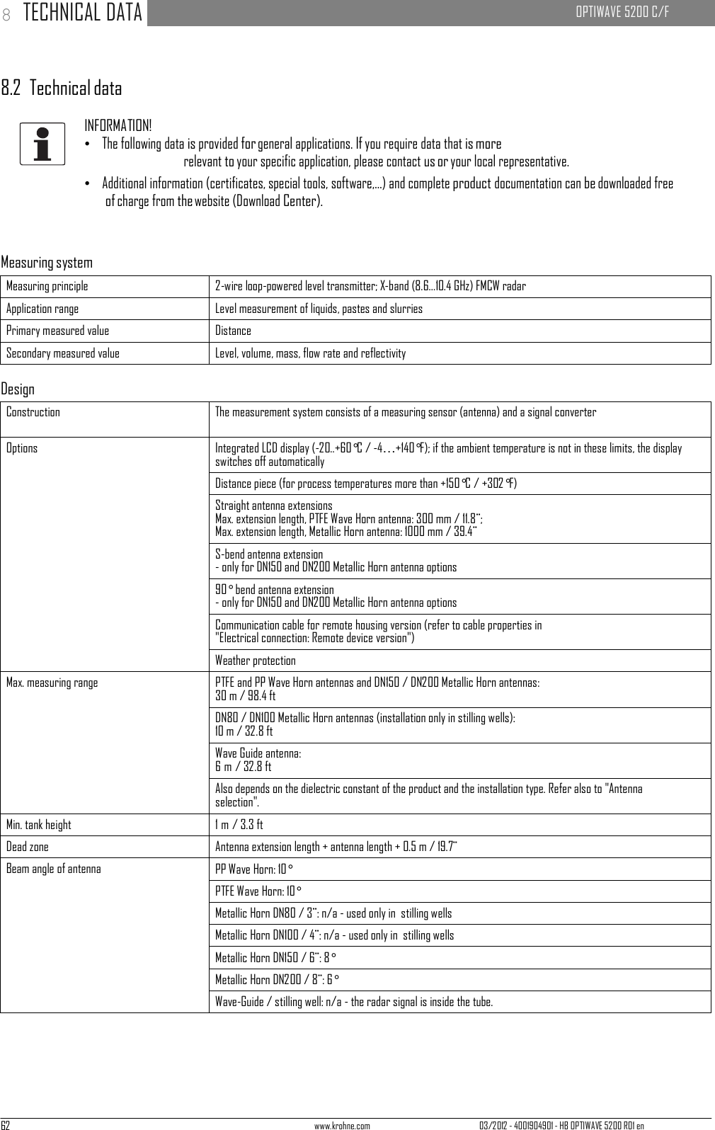
![64 www.krohne.com 03/2012 - 4001904901 - HB OPTIWAVE 5200 R01 en 8 TECHNICAL DATA OPTIWAVE 5200 C/F Installation conditions Process connection size The nominal diameter (DN) should be equal to or larger than the antenna diameter. Process connection position Make sure that there are not any obstructions directly below the process connection for the device. For more data, refer to Installation on page 16. Dimensions and weights Refer to "Technical data: Dimensions and weights". Materials Housing Standard: Aluminium with a polyester topcoat Option: Stainless steel (1.4404 / 316L) Wetted parts, including antenna Plastic Wave Horn antenna: PTFE or PP only Mettalic Wave Horn and Wave Guide antennas: Stainless steel (1.4404 / 316L) - refer also to "Gaskets" Process connection PP Wave Horn antenna: PP PTFE Wave Horn antenna: Stainless steel (1.4404 / 316L) with a PTFE plate / lining Metallic Horn and Wave Guide antennas: Stainless steel (1.4404 / 316L) Gaskets PP and PTFE Wave Horn antennas: n/a (gaskets are not supplied) Metallic Horn and Wave Guide antennas: FKM/FPM (-40…+200°C/ -40…+392°F); Kalrez® 6375 (-20…+250°C/ -4…+482°F); PFA (-60°C…+150°C/ -58…+302°F); EPDM (-50...+130°C / -58...+266°F) 1 Feedthrough PP and PTFE Wave Horn antennas: n/a Metallic Horn and Wave Guide antennas: Metaglas® 2 Cable gland Plastic (Non-Ex: black, Ex i-approved: blue); nickel-plated brass (Ex d devices only); stainless steel (Ex d devices only) Weather protection (Option) Stainless steel (1.4404 / 316L) - for the compact version only Process connections Thread PP Wave Horn antenna: G 1½; 1½ NPT Flange version EN PTFE Wave Horn antenna: DN50…150 in PN16, PN40 Metallic Horn and Wave Guide antennas: DN50…150 in PN16, PN40; DN200 in PN16; others on request ASME PTFE Wave Horn antenna: 2¨…6¨ in 150 lb / 300 lb Metallic Horn and Wave Guide antennas: 3¨…6¨ in 150 lb / 300 lb; 8¨ in 300 lb; others on request JIS PTFE Wave Horn antenna: 50A in 10K Metallic Horn and Wave Guide antennas: 80…200A in 10K; others on request Other Others on request Electrical connections Power supply Terminals output - Non-Ex / Ex i: 12…30 VDC; min./max. value for an output of 22 mA at the terminal Terminals output - Ex d: 16…36 VDC; min./max. value for an output of 22 mA at the terminal Current output load Non-Ex / Ex i: RL [Ω] ≤ ((Uext -13 V)/22 mA). For more data, refer to Minimum power supply voltage on page 86. Ex d: RL [Ω] ≤ ((Uext -16 V)/22 mA). For more data, refer to Minimum power supply voltage on page 86. Cable entry Standard: M20×1.5; Option: ½ NPT](https://usermanual.wiki/KROHNE/FMCW10G52.User-Manual/User-Guide-1893999-Page-64.png)
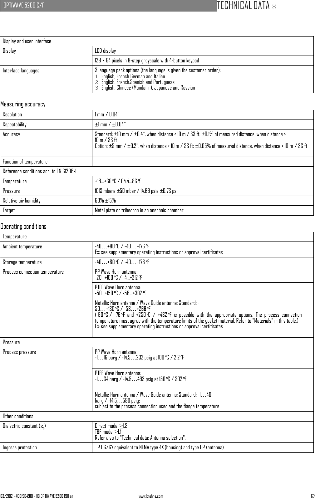
![03/2012 - 4001904901 - HB OPTIWAVE 5200 R01 en www.krohne.com 65 OPTIWAVE 5200 C/F TECHNICAL DATA 8 Cable gland Standard: none Options: M20×1.5 (cable diameter: 6...10 mm / 0.23...0.39¨); others are available on request Cable entry capacity (terminal) 0.5…1.5 mm² Input and output Output signal 4…20 mA HART® or 3.8…20.5 mA acc. to NAMUR NE 43 3 Resolution ±3 µA Temperature drift Typically 50 ppm/K Error signal High: 22 mA; Low: 3.6 mA acc. to NAMUR NE 43 Approvals and certification CE This device fulfils the statutory requirements of the EC directives. The manufacturer certifies successful testing of the product by applying the CE mark. Vibration resistance EN 60068-2-64 Metallic Horn: (DN200): 5 Hz to 100 Hz: 4g PTFE or PP Wave Horn: 3.5 mm up to 8 Hz and 10 m/s²: 1g, 8.5 to 2000 Hz Explosion protection ATEX (pending) KEMA 10ATEX0036 X II 1/2 G, 2 G Ex ia IIC T6...T2 Ga/Gb or Ex ia IIC T6...T2) Gb; II 1/2 D, 2 D Ex ia IIIC T90°C Da/Db or Ex ia IIIC T90°C Db IP6X; II 1/2 G, 2 G Ex d ia IIC T6...T3 (or T2) Ga/Gb or Ex d ia IIC T6...T3 (or T2) Gb; II 1/2 D, 2 D Ex ia tb IIIC T90°C Da/Db or Ex ia tb IIC T90°C Db IP6X IECEx (pending) IECEx KEM 10.0006 X Ex ia IIC T6…T3 (or T2) Ga/Gb or Ex ia IIC T6…T3 (or T2) Gb; Ex ia IIIC T90°C Da/Db or Ex ia IIIC T90°C Db IP6X; Ex d ia IIC T6...T3 (or T2) or Ex d ia IIC T6...T3 (or T2) Gb; Ex ia tb IIIC T90°C Da/Db or Ex ia tb IIIC T90°C IP6X cFMus - Dual Seal-approved (pending) NEC 500 XP-IS / Cl. I / Div. 1 / Gr. ABCD / T6; DIP / Cl. II/III / Div. 1 / Gr. EFG / T6; IS / Cl. I/II/III / Div. 1 / Gr. ABCDEFG / T6; NI / Cl. I / Div. 2 / Gr. ABCD / T6 NEC 505 Cl. I / Zone 0 / AEx d [ia] / IIC / T6; Cl. I / Zone 0 / AEx ia / IIC / T6; Cl. I / Zone 2 / AEx nA [ia] / IIC / T6; Hazardous (Classified) Locations, indoor/outdoor Type 4X and 6P, IP66, Dual Seal CEC Section 18 (Zone ratings) Cl. I, Zone 1, Ex d, IIC (Antenna: Zone 0), T6; Cl. I, Zone 0, Ex ia, IIC, T6; Cl. I, Zone 2, Ex nA, IIC, T6 DIP A21 IP66 TB 95°C CEC Section 18 and Annex J (Division ratings) Cl. I, Div. 1/2, Gr. ABCD; Cl. II, Gr. EFG; Cl. III, T6; NEPSI (pending) Ex ia IIC T2~T6 DIP A21 TA IP66; Ex dia IIC T2~T6 DIP A21 TA IP66](https://usermanual.wiki/KROHNE/FMCW10G52.User-Manual/User-Guide-1893999-Page-65.png)