KROHNE FMCW06G10 Radar Level Meter User Manual HB OPTIWAVE1010 en 140930 4003537401 R01
KROHNE Radar Level Meter HB OPTIWAVE1010 en 140930 4003537401 R01
UserManual.wiki
>
KROHNE
>
FMCW06G10 User Manual
User Manual
Navigation menu
Upload a User Manual
Namespaces
Wiki Guide
HTML
PDF
Info
Views
User Manual
Discussion / Help
Navigation
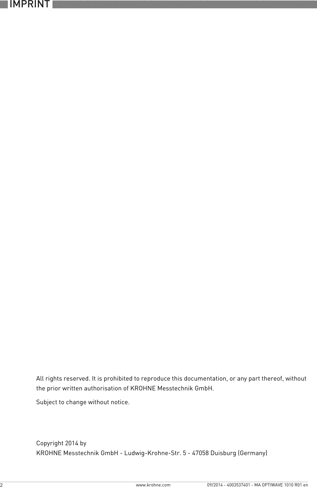
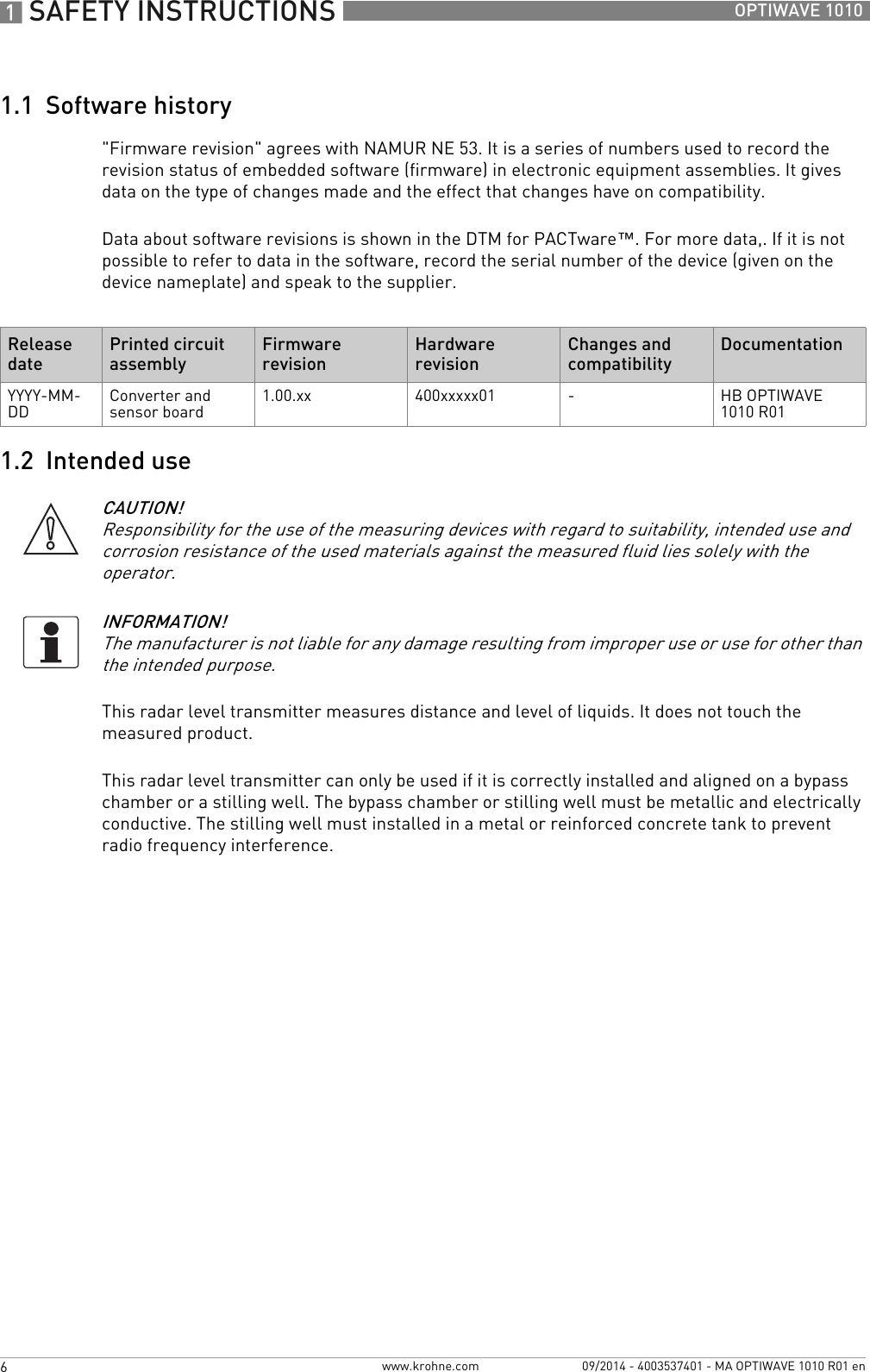
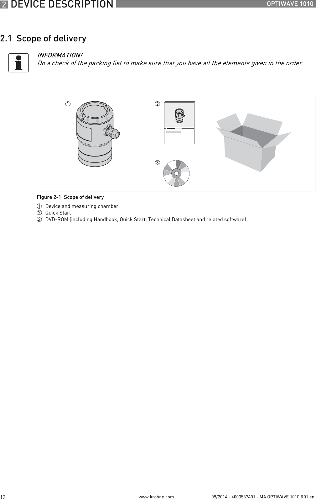
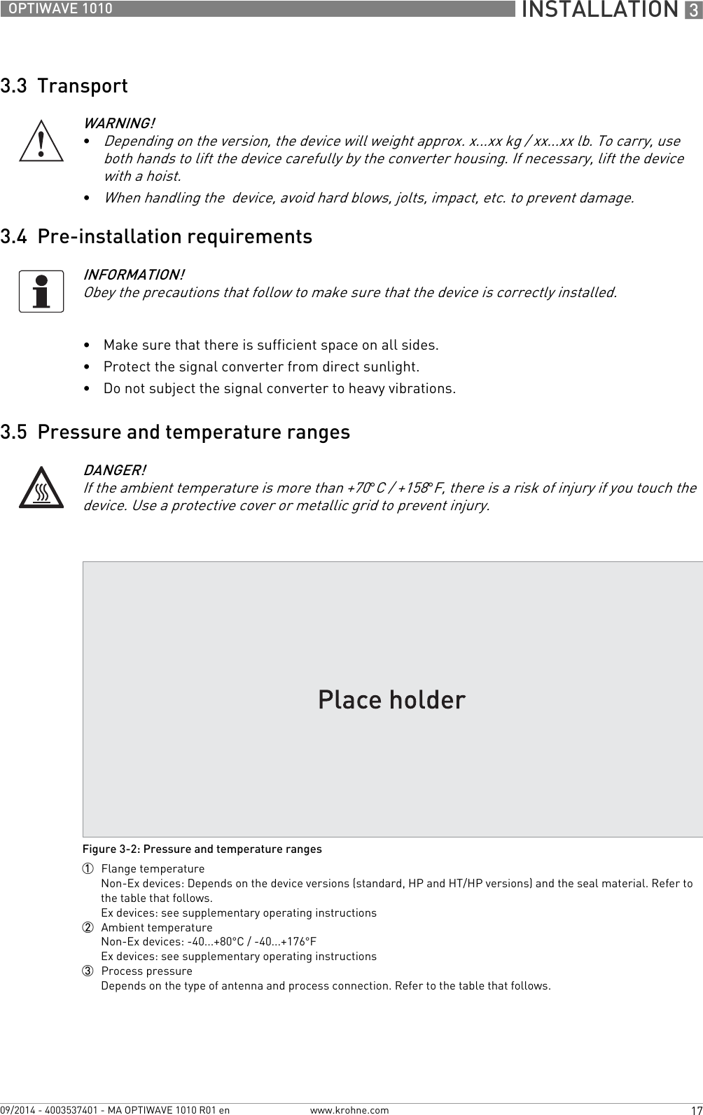
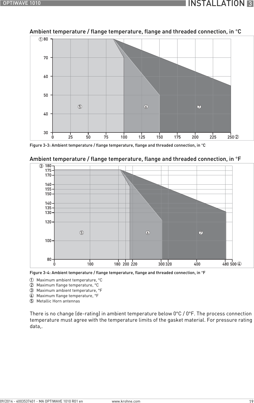
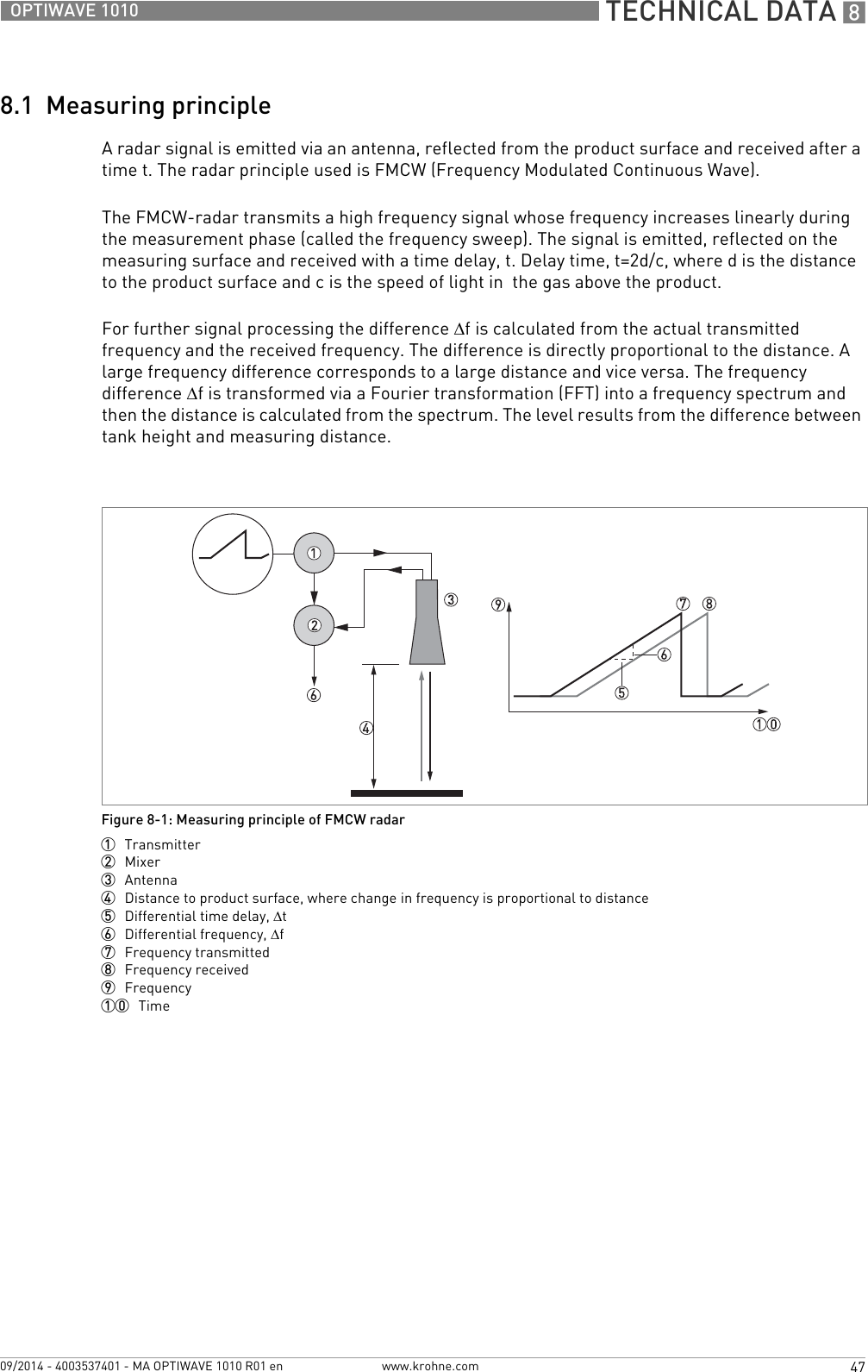
![3 INSTALLATION 18 OPTIWAVE 1010www.krohne.com 09/2014 - 4003537401 - MA OPTIWAVE 1010 R01 enAluminium housing for non-Ex and Ex i-approved devicesStainless steel housing for non-Ex and Ex d-approved devicesFor more data on pressure ratings, refer to Pressure ratings on page 54Version Seal Temperature extensionProcess connection temperatureProcess pressure[°C] [°F] [barg] [psig]Standard FKM/FPM with PEEKwithout -30...+100 -22...+212 -1...16 -14.5...232Kalrez® 6375 with PEEKwithout -20...+100 -4...+212EPDM with PEEK without -40...+100 -40...+212HP 1 FKM/FPM with Metaglas®without -30...+100 -22...+212 -1...40 -14.5...580Kalrez® 6375 with Metaglas®without -20...+100 -4...+212EPDM with Metaglas®without -40...+100 -40...+212HT or HT/HP 1FKM/FPM with Metaglas®with -30...+150 -22...+302 -1...40 -14.5...580Kalrez® 6375 with Metaglas®with -20...+150 -4...+302EPDM with Metaglas®With -40...+120 -40...+2481HP = high-pressure version. HT = high-temperature version. HT/HP = high-pressure / high-temperature version.Version Seal Temperature extensionProcess connection temperatureProcess pressure[°C] [°F] [barg] [psig]Standard FKM/FPM with Metaglas®without -30...+150 -22...+302 -1...40 -14.5...580Kalrez® 6375 with Metaglas®without -20...+150 -4...+302EPDM with Metaglas®without -40...+120 -40...+248](https://usermanual.wiki/KROHNE/FMCW06G10/User-Guide-2432498-Page-18.png)
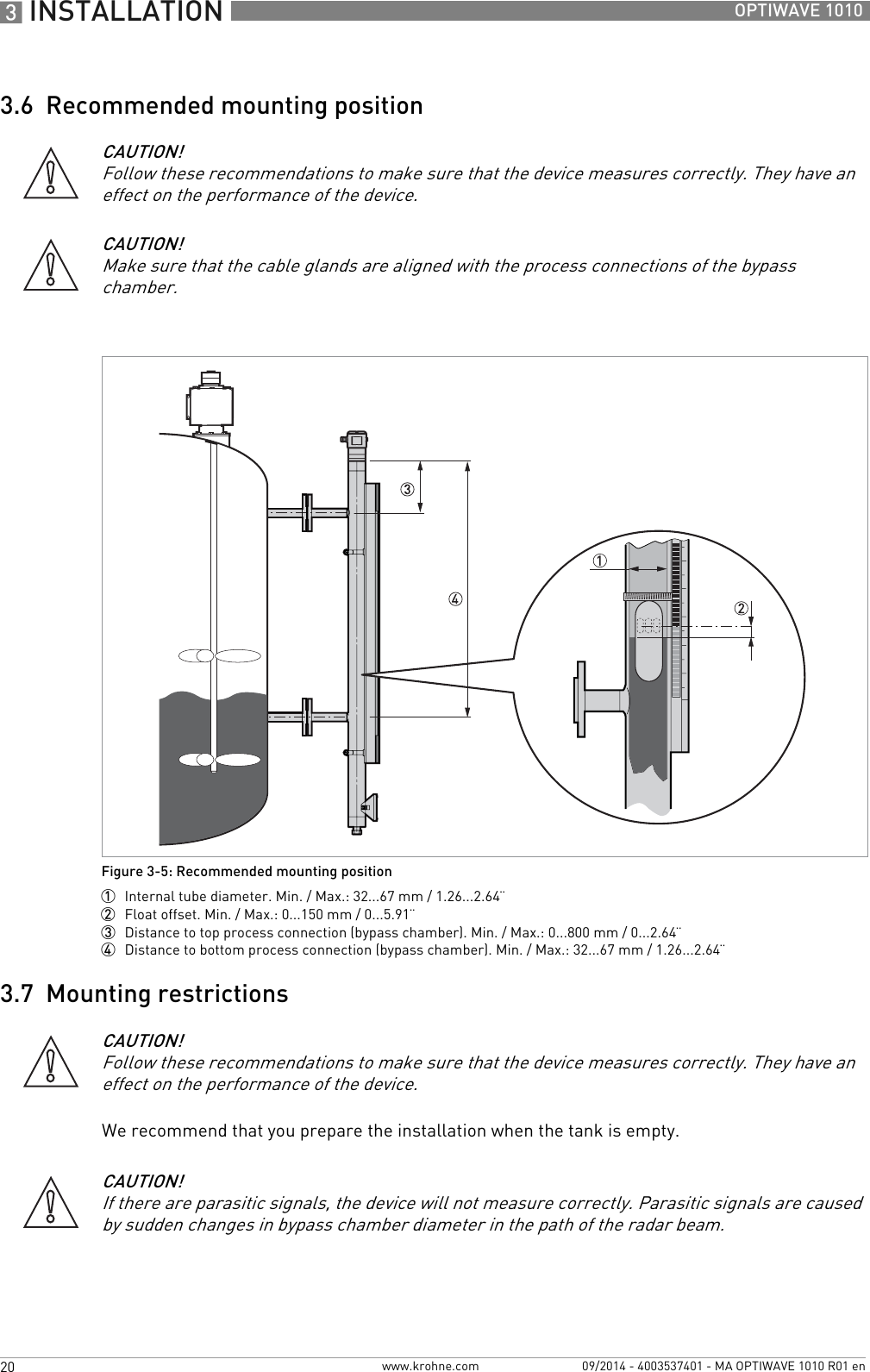
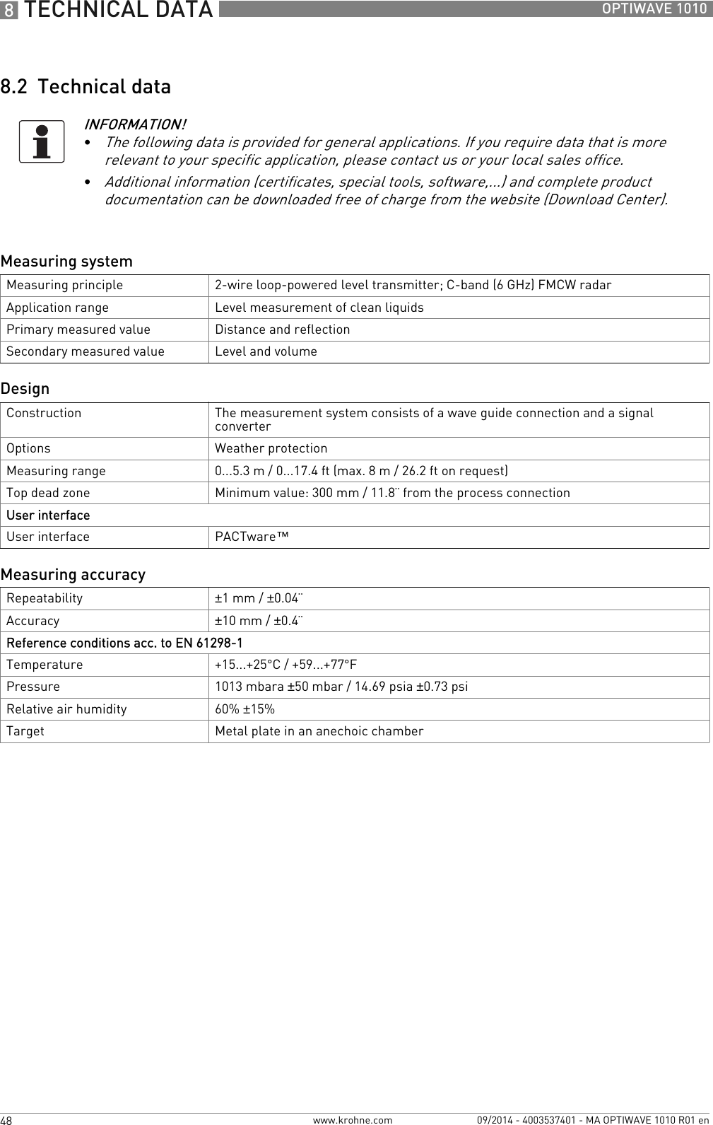
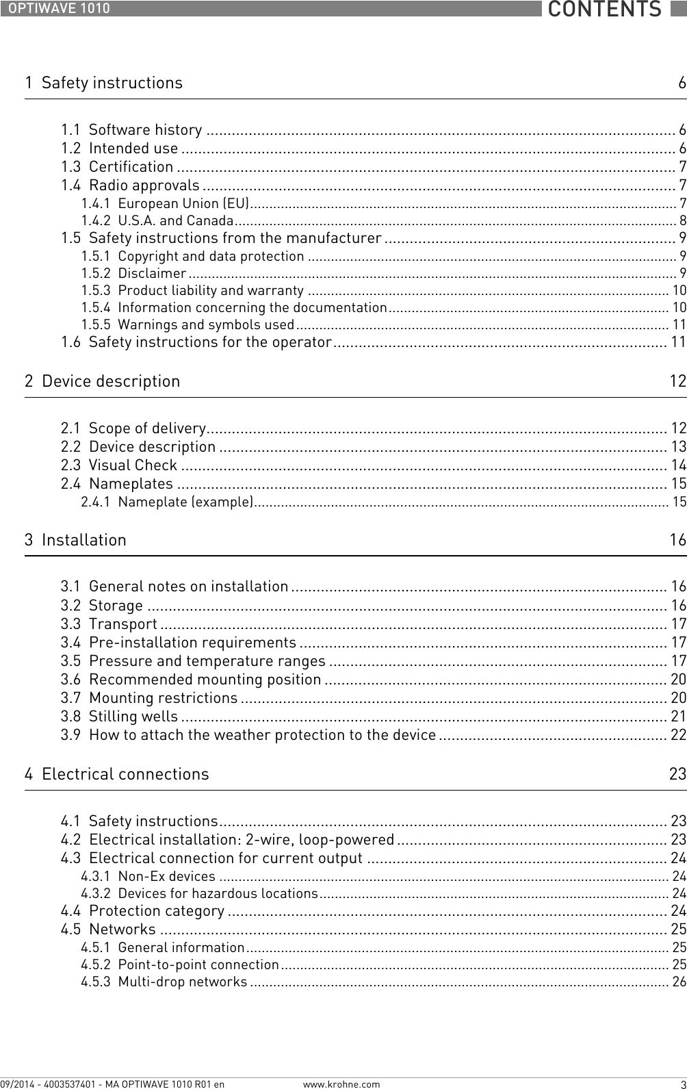
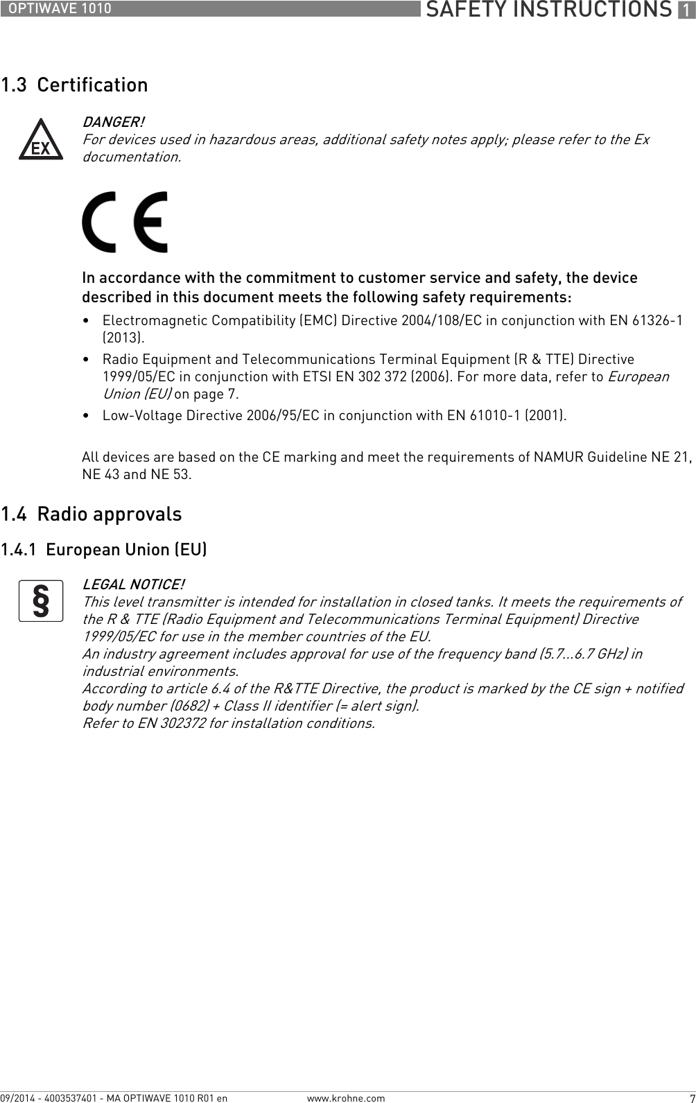
![8 TECHNICAL DATA 50 OPTIWAVE 1010www.krohne.com 09/2014 - 4003537401 - MA OPTIWAVE 1010 R01 enProcess connectionsWelded versionPipe sizes Stainless steel (1.4404 / 316L): Ø42.4×2; Ø60.3×2; Ø60.3×2.77; Ø60.3×3.9Hastelloy® C-22® (2.4602) : Ø42.4×2; Ø60.3×2; Ø60.3×2.77; Ø60.3×3.9Flange versionEN 1092-1 DN40…80 (Form B1, B2, C, D, E or F) in PN16 / 40; others are available on requestASME B16.5 1½...3¨ (RF or FF) in 150 lb / 300 lb; others are available on requestJIS 40...80A in 10KElectrical connectionsPower supply 14.5…30 VDC; min./max. value for an output of 22 mA at the terminalMaximum current 22 mACurrent output load RL [Ω] ≤ ((Uext -14.5 V)/22 mA). For more data, refer to Minimum power supply voltage on page 53.Cable entry Standard: M20×1.5; Option: ½NPTCable gland Standard: noneOptions: M20×1.5 (cable diameter: 6...10 mm / 0.2...0.39¨); others are available on requestCable entry capacity (terminal) 0.5…2.5 mm²Input and outputCurrent output / HART®Output signal 4…20 mA HART® or 3.8…20.5 mA acc. to NAMUR NE 43 4Resolution ±3µATemperature drift Typically 50 ppm/K (150 ppm/K maximum)Digital temperature drift Max. ±15 mm / 0.6¨ for the full temperature rangeError signal High: 22 mA; Low: 3.6 mA acc. to NAMUR NE 43 5Approvals and certificationCE This device fulfils the statutory requirements of the EC directives. The manufacturer certifies successful testing of the product by applying the CE mark.Vibration resistance EN 60068-2-6 / IEC 61298-310-82.2 Hz: 0.15 mm; 82.2-1000 Hz: 20 m/s²](https://usermanual.wiki/KROHNE/FMCW06G10/User-Guide-2432498-Page-50.png)
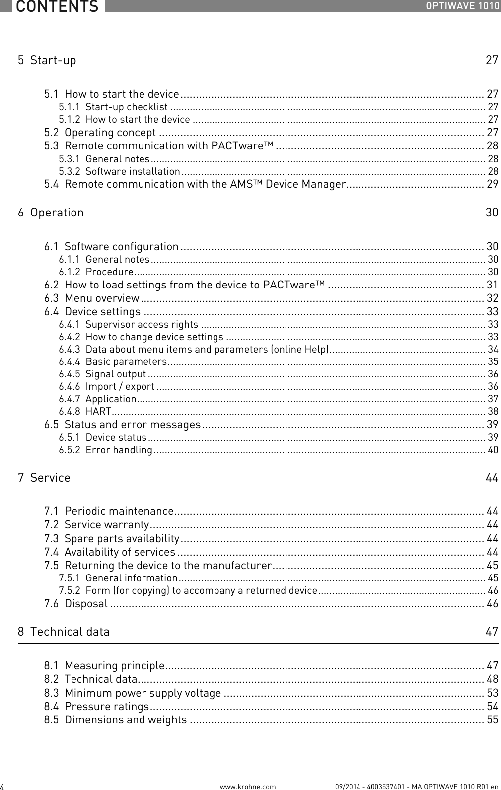
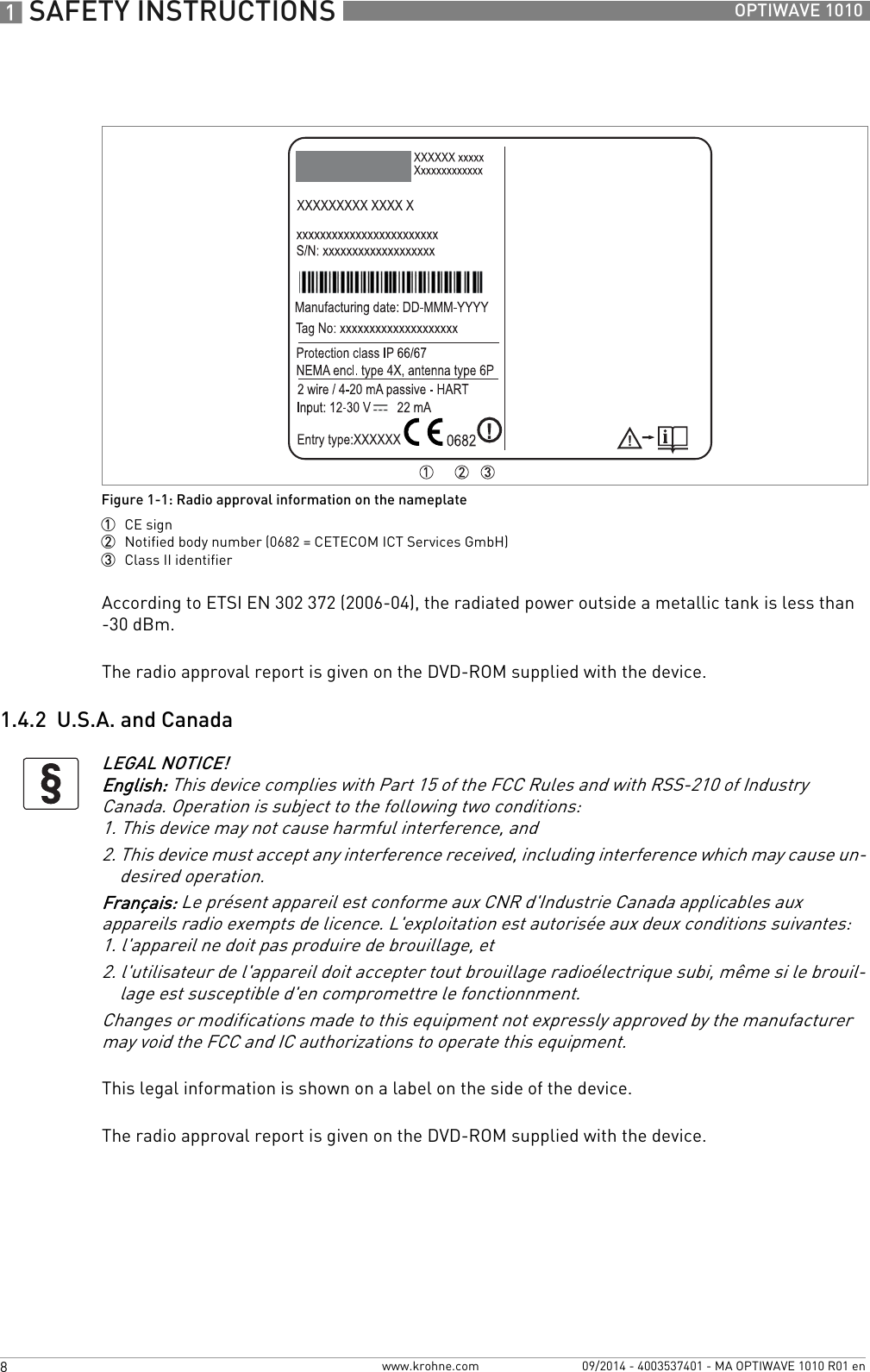
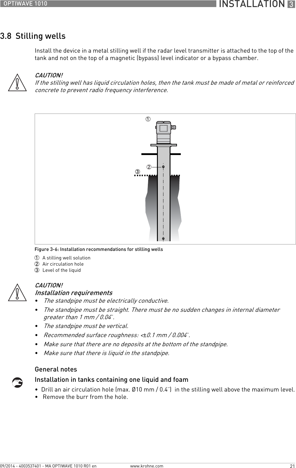
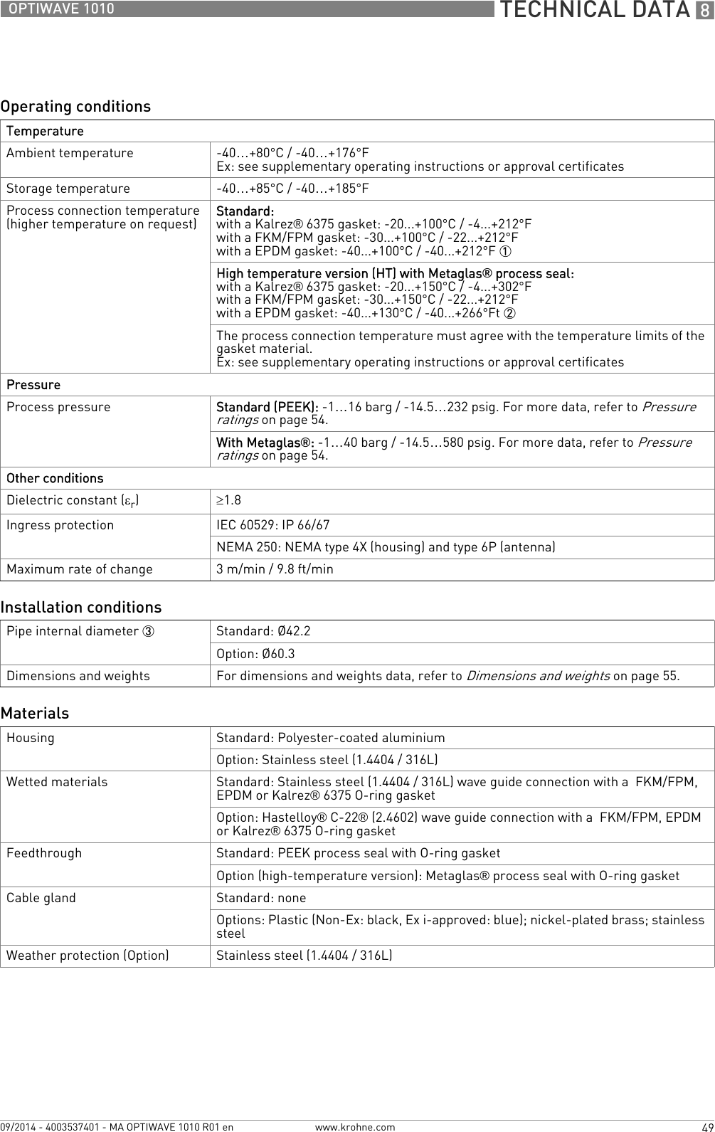
![TECHNICAL DATA 851OPTIWAVE 1010www.krohne.com09/2014 - 4003537401 - MA OPTIWAVE 1010 R01 enExplosion protectionATEX (Ex ia or Ex d)DEKRA xxATEXxxxx X(pending)II 1/2 G, 2 G Ex ia IIC T6...T2 Ga/Gb or Ex ia IIC T6...T2 Gb;II 1/2 D, 2 D Ex ia IIIC T90°C Da/Db or Ex ia IIIC T90°C Db IP6X;II 1/2 G, 2 G Ex d ia IIC T6...T2 Ga/Gb or Ex d ia IIC T6...T2 Gb;II 1/2 D, 2 D Ex ia tb IIIC T90°C Da/Db or Ex ia tb IIIC T90°C Db IP6XATEX (Ex ic)DEKRA xxATEXxxxx X(pending)II 3 G Ex ic IIC T6...T2 Gc;II 3 D Ex ic IIIC T90°C DcIECExIECEx DEK xx.xxxx X(pending)Ex ia IIC T6…T2 Ga/Gb or Ex ia IIC T6…T2 Gb or Ex ic IIC T6…T2 Gc;Ex ia IIIC T90°C Da/Db or Ex ia IIIC T90°C Db or Ex ic IIIC T90°C Dc;Ex d ia IIC T6...T2 or Ex d ia IIIC T6...T2 Gb;Ex ia tb IIIC T90°C Da/Db or Ex ia tb IIIC T90°C DbcFMus– Dual Seal-approved(pending)NEC 500 (Division ratings)XP-AIS / Cl. I / Div. 1 / Gr. ABCD / T6-T1;DIP / Cl. II, III / Div. 1 / Gr. EFG / T6-T1;IS / Cl. I, II, III / Div. 1 / Gr. ABCDEFG / T6-T1;NI / Cl. I / Div. 2 / Gr. ABCD / T6-T1NEC 505 (Zone ratings)Cl. I / Zone 0 / AEx d [ia] / IIC / T6-T1;Cl. I / Zone 0 / AEx ia / IIC / T6-T1;Cl. I / Zone 2 / AEx nA / IIC / T6-T1;Zone 20 / AEx ia / IIIC / T90°CZone 20 / AEx tb [ia] / IIIC / T90°CHazardous (Classified) Locations, indoor/outdoor Type 4X and 6P, IP66, Dual SealCEC Section 18 (Zone ratings)Cl. I, Zone 0, Ex d [ia], IIC, T6-T1;Cl. I, Zone 0, Ex ia, IIC, T6-T1;Cl. I, Zone 2, Ex nA, IIC, T6-T1CEC Section 18 and Annex J (Division ratings)XP-AIS / Cl. I / Div. 1 / Gr. BCD / T6-T1DIP / Cl. II, III / Div. 1 / Gr. EFG / T6-T1IS/ Cl.I/ Div.1/ Gr.BCD/ T6-T1NI / Cl. I / Div. 2 / Gr. ABCD / T6-T1NEPSI(pending) Ex ia IIC T2~T6 Gb or Ex ia IIC T2~T6 Ga/Gb DIP A20/A21 TA T90°C IP6XEx d ia IIC T2~T6 Gb or Ex d ia IIC T2~T6 Ga/Gb DIP A20/A21 TA T90°C IP6X](https://usermanual.wiki/KROHNE/FMCW06G10/User-Guide-2432498-Page-51.png)
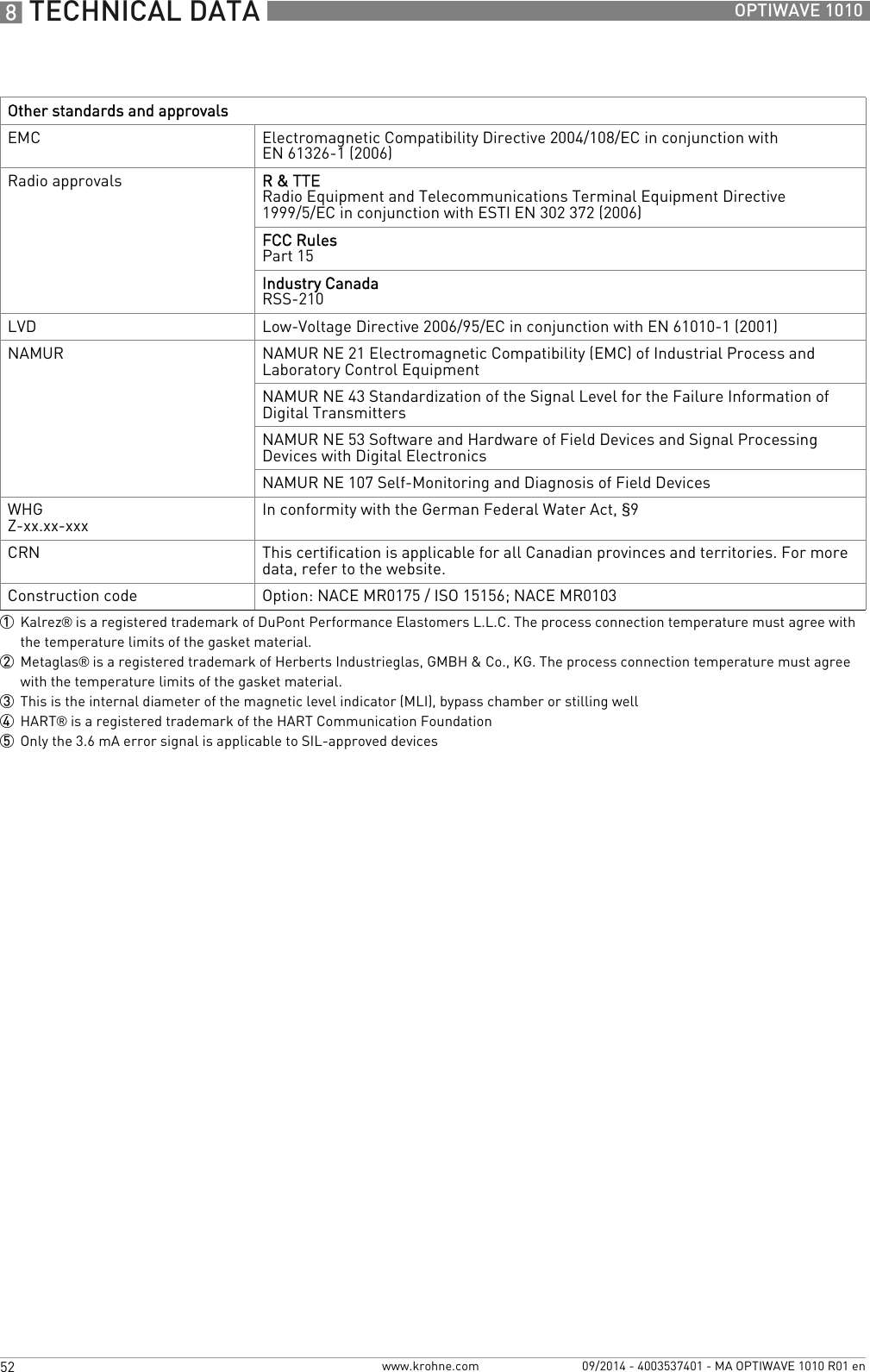
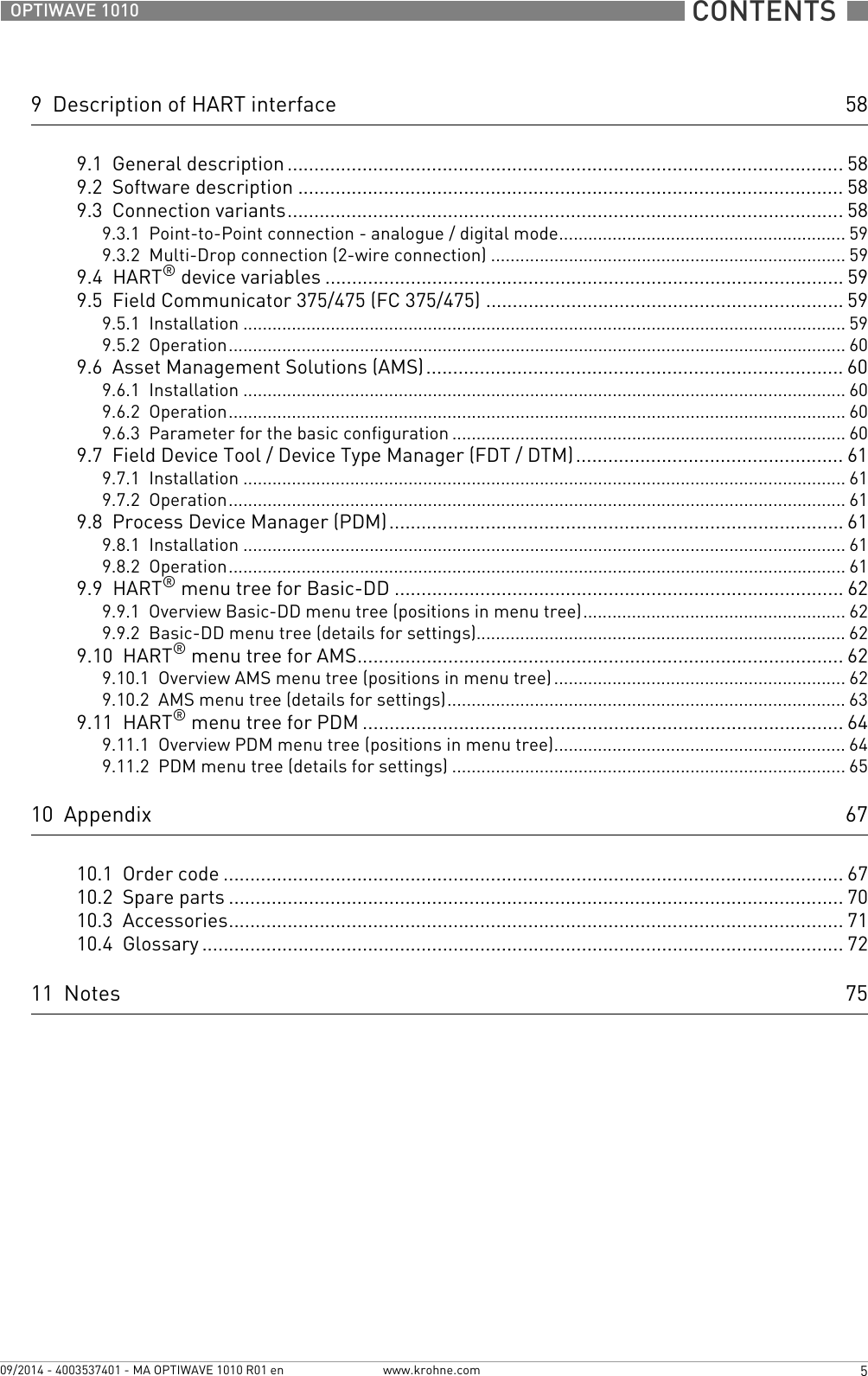
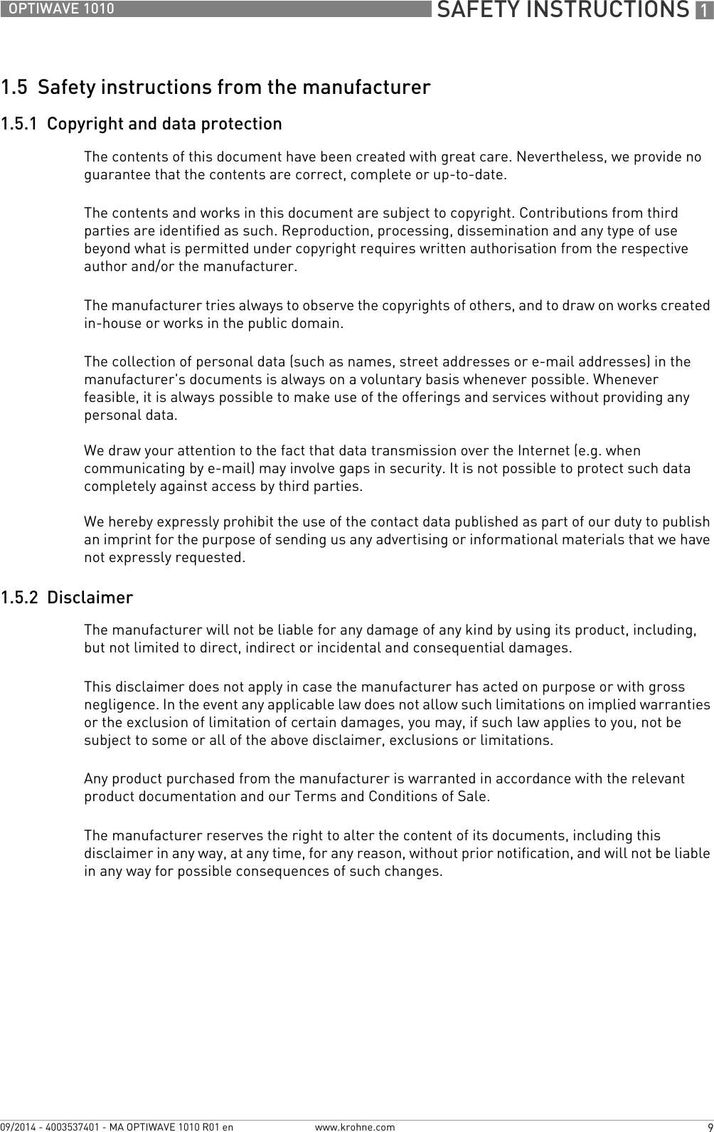
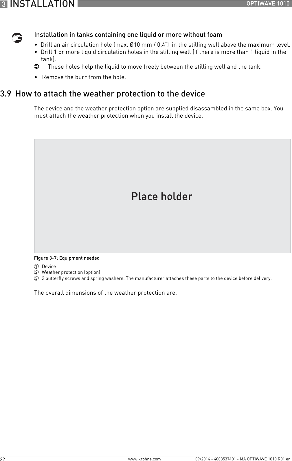
![TECHNICAL DATA 853OPTIWAVE 1010www.krohne.com09/2014 - 4003537401 - MA OPTIWAVE 1010 R01 en8.3 Minimum power supply voltageUse these graphs to find the minimum power supply voltage for a given current output load.Non-Ex and Hazardous Location approved (Ex i / IS) devicesFigure 8-2: Minimum power supply voltage for an output of 22 mA at the terminal (Non-Ex and Hazardous Location approval (Ex i / IS))X: Power supply U [VDC]Y: Current output load RL [Ω]Hazardous Location (Ex d / XP/NI) approved devicesFigure 8-3: Minimum power supply voltage for an output of 22 mA at the terminal (Hazardous Location approval (Ex d / XP/NI))X: Power supply U [VDC]Y: Current output load RL [Ω]](https://usermanual.wiki/KROHNE/FMCW06G10/User-Guide-2432498-Page-53.png)
![8 TECHNICAL DATA 54 OPTIWAVE 1010www.krohne.com 09/2014 - 4003537401 - MA OPTIWAVE 1010 R01 en8.4 Pressure ratingsThis data is only applicable to the flanged version of the device.WARNING!Make sure that the devices are used within their operating limits. This will depend on the device version, feedthrough material and process seal materal.EN flangesFigure 8-4: Pressure / temperature rating (EN 1092-1), flange connections, in °C and bargFigure 8-5: Pressure / temperature rating (EN 1092-1), flange connections, in °F and psig1 p [barg]2 T [°C]3 p [psig]4 T [°F]5 Flange connection, PN166 Flange connection, PN40](https://usermanual.wiki/KROHNE/FMCW06G10/User-Guide-2432498-Page-54.png)
![TECHNICAL DATA 855OPTIWAVE 1010www.krohne.com09/2014 - 4003537401 - MA OPTIWAVE 1010 R01 en8.5 Dimensions and weightsDevice versions: Dimensions in mm and inchesDevice versionsFigure 8-6: Device versions1 Non-Ex or Ex i-approved version (aluminium housing – standard or high-pressure (HP) version)2 High-temperature / high-pressure (HT/HP) version3 Non-Ex or Ex d-approved version (stainless steel housing – standard version)Dimensions Device versionsAluminium:non-Ex or Ex i-approved (standard or HP)Aluminium:HT/HPStainless steel:non-Ex or Ex d-approved[mm] [inches] [mm] [inches] [mm] [inches]a98 3.86 98 3.86 99.5 3.92b178 7.01 278 10.94 189 7.44c138 5.43 138 5.43 133 5.24d153 6.02 253 9.96 164 6.46e14 0.55 14 0.55 14 0.55f42.4 1.67 42.4 1.67 42.4 1.67g90 3.54 90 3.54 90 3.54h64.5 2.54 164 6.47 60 2.36](https://usermanual.wiki/KROHNE/FMCW06G10/User-Guide-2432498-Page-55.png)
![8 TECHNICAL DATA 56 OPTIWAVE 1010www.krohne.com 09/2014 - 4003537401 - MA OPTIWAVE 1010 R01 enDimensions and weights in mm and kgDimensions and weights in inches and lbWeather protection optionFigure 8-7: Weather protection option for Compact / Vertical and Remote versionsFigure 8-8: Weather protection option for Compact / Horizontal and Remote versions1 Left side (with weather protection open)2 Rear view (with weather protection closed)3 Right side (with weather protection closed)Weather protection Dimensions [mm] Weights [kg]a b c dCompact / Vertical or Remote versions 244 170 274 285 1.6Compact / Horizontal or Remote versions 221 170 274 269 1.6Weather protection Dimensions [inches] Weights [lb]a b c dCompact / Vertical or Remote versions 9.6 6.7 10.8 11.22 3.5Compact / Horizontal or Remote versions 8.7 6.7 10.8 10.59 3.5](https://usermanual.wiki/KROHNE/FMCW06G10/User-Guide-2432498-Page-56.png)
![TECHNICAL DATA 857OPTIWAVE 1010www.krohne.com09/2014 - 4003537401 - MA OPTIWAVE 1010 R01 enWeightsType of device Weights Aluminium Stainless steel[kg] [lb] [kg] [lb]Non-Ex / intrinsically-safe (Ex i / IS)Standard x.x x.x x.x x.xHigh temperature x.x x.x x.x x.xExplosion proof (Ex d / XP)Standard x.x x.x x.x x.x](https://usermanual.wiki/KROHNE/FMCW06G10/User-Guide-2432498-Page-57.png)