KROHNE 702 Level Radar User Manual BM702 MBA e
Krohne America Inc Level Radar BM702 MBA e
UserManual.wiki
>
KROHNE
>
702 User Manual
>
Manual
Contents
1.
Manual
2.
Addendum to manual
Manual
Navigation menu
Upload a User Manual
Namespaces
Wiki Guide
HTML
PDF
Info
Views
User Manual
Discussion / Help
Navigation
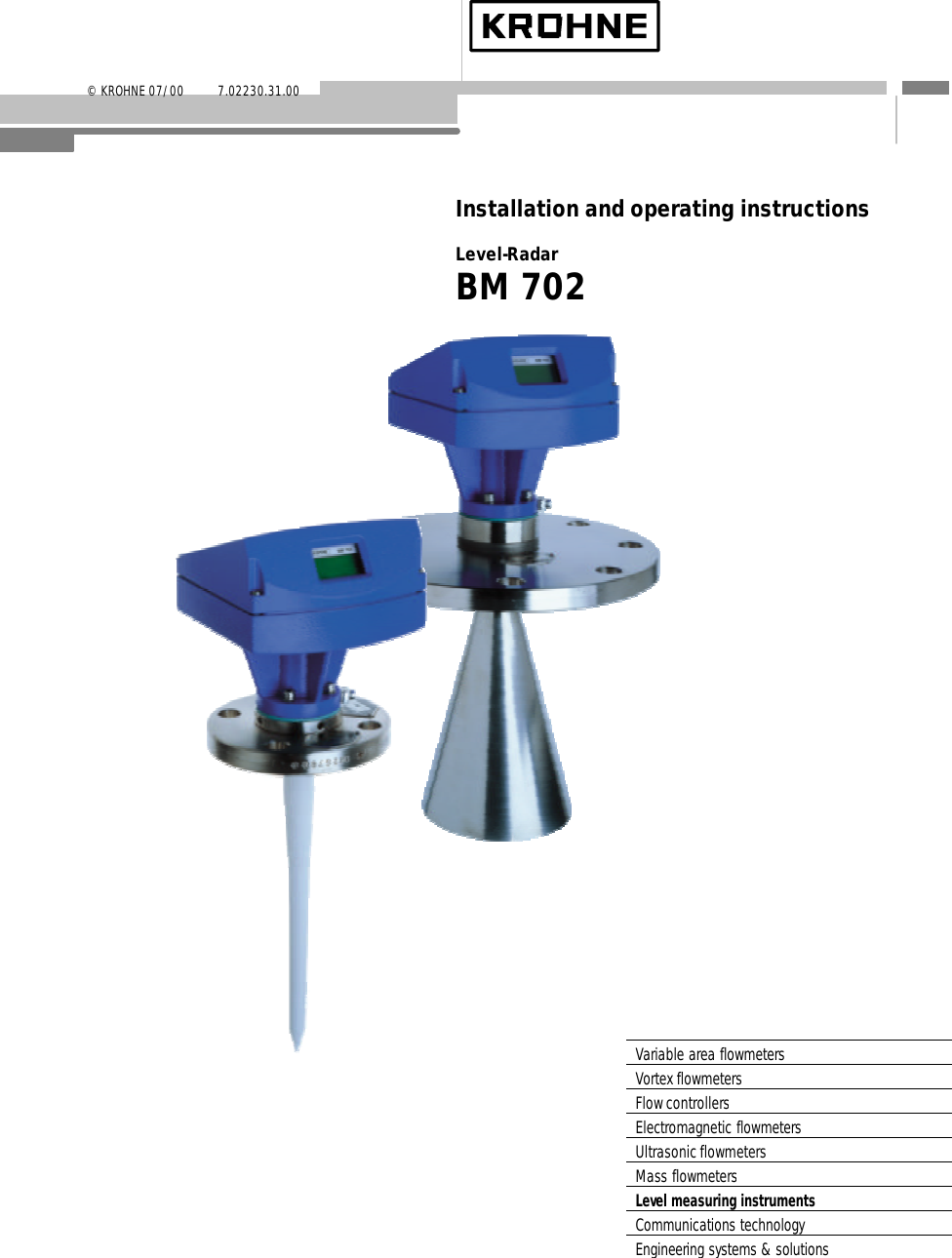
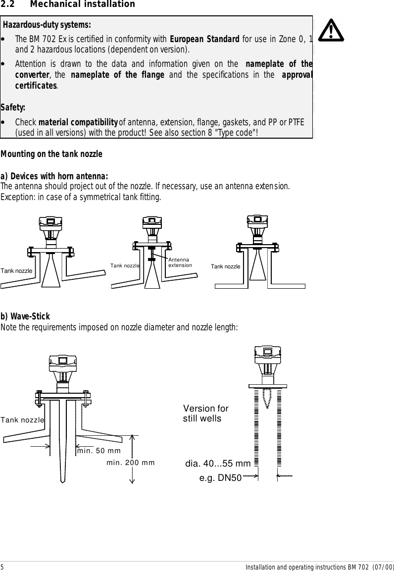
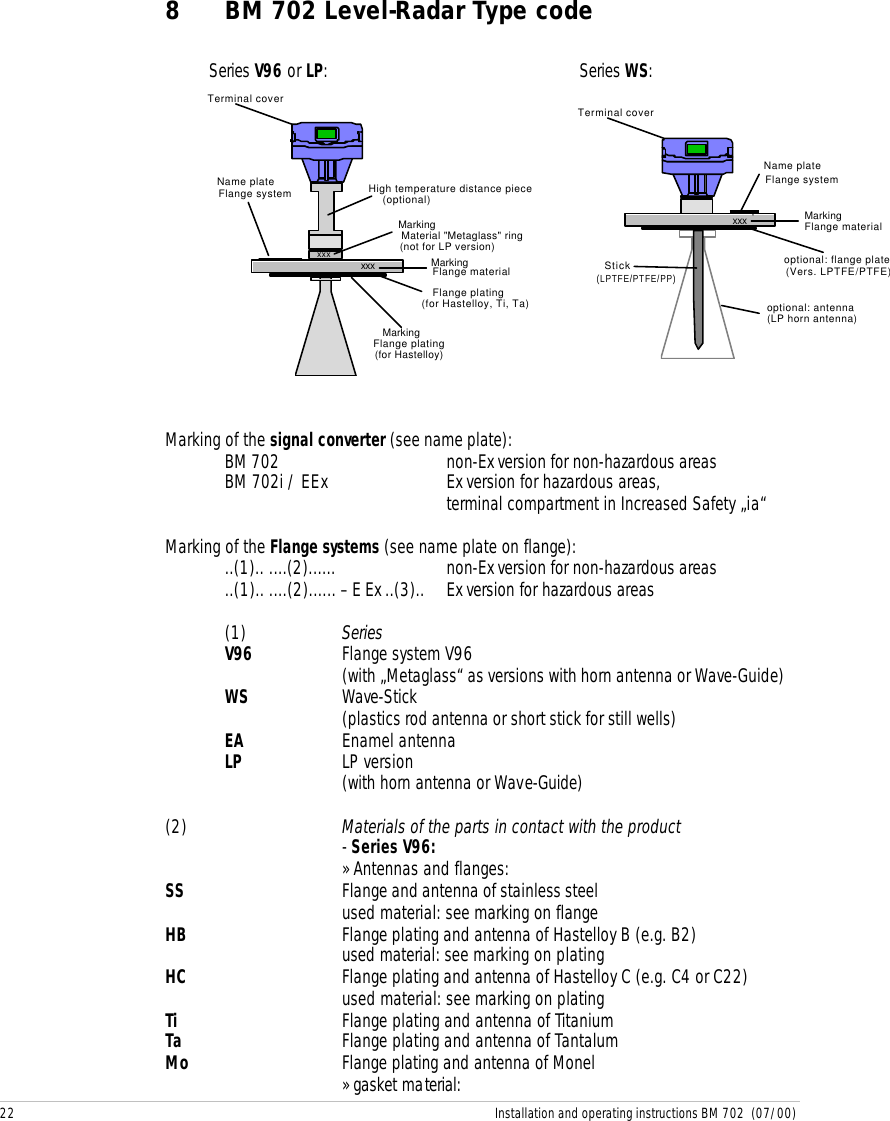
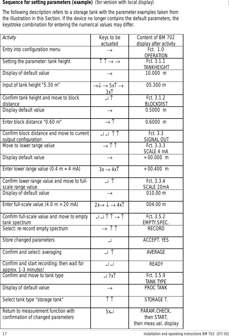
![11 Installation and operating instructions BM 702 (07/00)Description of functionsThe table on the following 3 pages provides an overview of all parameters that can be set inthe configuration menu.This is followed by more precise explanations of some functions and a typical configuration.Configuration menu (version 7.00)Function (Fct.) Input range Description1.0 OPERATION1.1 DISPLAY1.1.1 FCT.DISP identical with 3.2.11.1.2 UNIT.LENGTH identical with 3.2.21.1.3 UNIT.CONV. identical with 3.2.32.0 TEST2.1 HARDWARE2.1.1 MASTER Master hardware test.2.1.2 DISPLAY Display hardware test.2.1.3 STATUS Status information for Service2.2 CUR.OUTP.I2.2.1 VALUE I Value display Display of actual value of thecurrent output.2.2.2 TEST I Select 3.6 mA/4 mA/6 mA/...... 20 mA/22 mA Output of selected value tothe current output. Withsafety query.2.4 FIRMWARE2.4.1 MASTER Display Display of master firmwareversion.3.0 INSTALL.3.1 BASIS.PARAM3.1.1 TANKHEIGHT Select unit m/cm/mm/inch/FtEnter 0.50 ... 20.00 [m]Enter tank height (seeexplanatory notes).The unit entered here is alsoused for all other lengthentries.3.1.2 BLOCKDIST Enter 0.10 [m] ... tank height Enter block distance = non-measurable range belowbottom edge of flange (seeexplanatory notes).3.1.3 ANTENNA Select STANDARDWAVE-STICK Select antenna type. WAVE-STICK for all Wave-Stickversions, except type "SW"for stillwells.All other = STANDARD.3.1.4 ANT.EXTENS. Enter 0.00 [m] ... tank height Enter length of antennaextension (not for Wave-Stick: set to= 0)3.1.5 DIST.PIECE Enter 0 ... 2000 [mm] Enter length of distancepiece above flange (hightemp. version = 120 mm).3.1.6 STILLWELL Select NO / YESIf “YES“: enter 25 ... 200 [mm] Selection: without or withstill well.With still well: enter insidediameter in [mm]](https://usermanual.wiki/KROHNE/702.Manual/User-Guide-237556-Page-11.png)
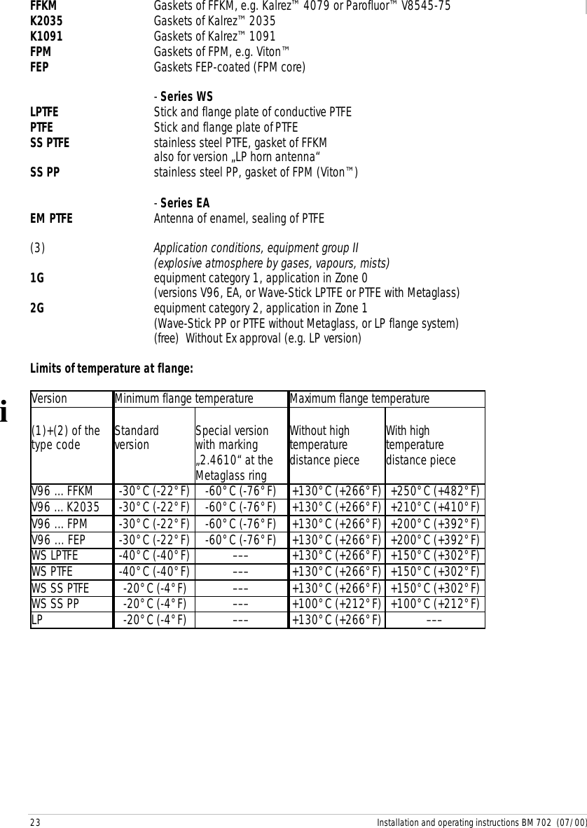
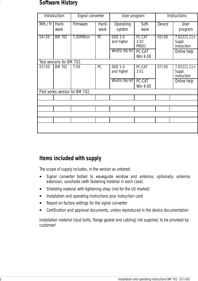
![12 Installation and operating instructions BM 702 (07/00)Function (Fct.) Input range Description(compensates differentwave speeds in still wells)3.1.7 REF.OFFSET Enter -10.00...0...+10.00 [m] Reference offset is addedto measured distancevalues.3.1.8 TB.OFFSET Enter-100.00...0...+100.00 [m] Tank bottom offset is addedto measured level values.3.2 DISPLAY3.2.1 FCT.DISP Select LEVELDISTANCECONVERSIONSelect function of display(value to be displayed).See also explanatory notes.3.2.2 UNIT.LENGTH Select m/cm/mm/inch/Ft/PERCENT/BARGRAPHSelect unit for length valueto be displayed (only forlevel and distance).3.2.3 UNIT.CONV. Select m3/l(Liter)/US Gal/GB Gal/Ft3/bbl/PERCENT/BARGRAPH/USER UNITSelect unit for conversionvalue to be displayed(“volume table“).(see explanatory notes)3.2.4 USER UNIT Text entry 10 characters Enter user-defined unit forthe conversion table.3.2.5 ERROR MSG. Select NO/YES Select whether errormessages to be shown indisplay.3.3 SIGNAL OUT3.3.1 FUNCTION I Select OFF/LEVEL/DISTANCE/CONVERSION/SW.OUTP. Select function of thecurrent output.3.3.2 RANGE I Select 4-20mA4-20mA/E3.64-20mA/E22Select range/error statusfor the current output (holdlast value or 3.6 mA/22mAin error status)3.3.3 SCALE 4mA Enter -200.00 ... +200.00 [m]0.00 ... 99999.99 [m3]Enter lower measuringrange value for the currentoutput (4 mA).(see explanatory notes)3.3.4 SCALE 20mA Enter -200.00 ... +200.00 [m]0.00 ... 99999.99 [m3]Enter full-scale range valuefor the current output (20mA).(see explanatory notes)3.3.5 BAUDRATE Select 1200 Bd Baud rate for HART®communication (do notchange!).3.3.6 ADDRESS Enter 0 ... 255 Enter device address.(for HART® multidrop)3.3.7 PROTOCOL Select HART/KROHNE-PC Select communicationsprotocol3.4 USER DATA3.4.1 LANGUAGE Select GB-USA/D/F/I/E/P/S Select language for theoptional display.3.4.2 ENTRY CODE 1 Select NO/YES Switch the access lockouton/off.](https://usermanual.wiki/KROHNE/702.Manual/User-Guide-237556-Page-12.png)
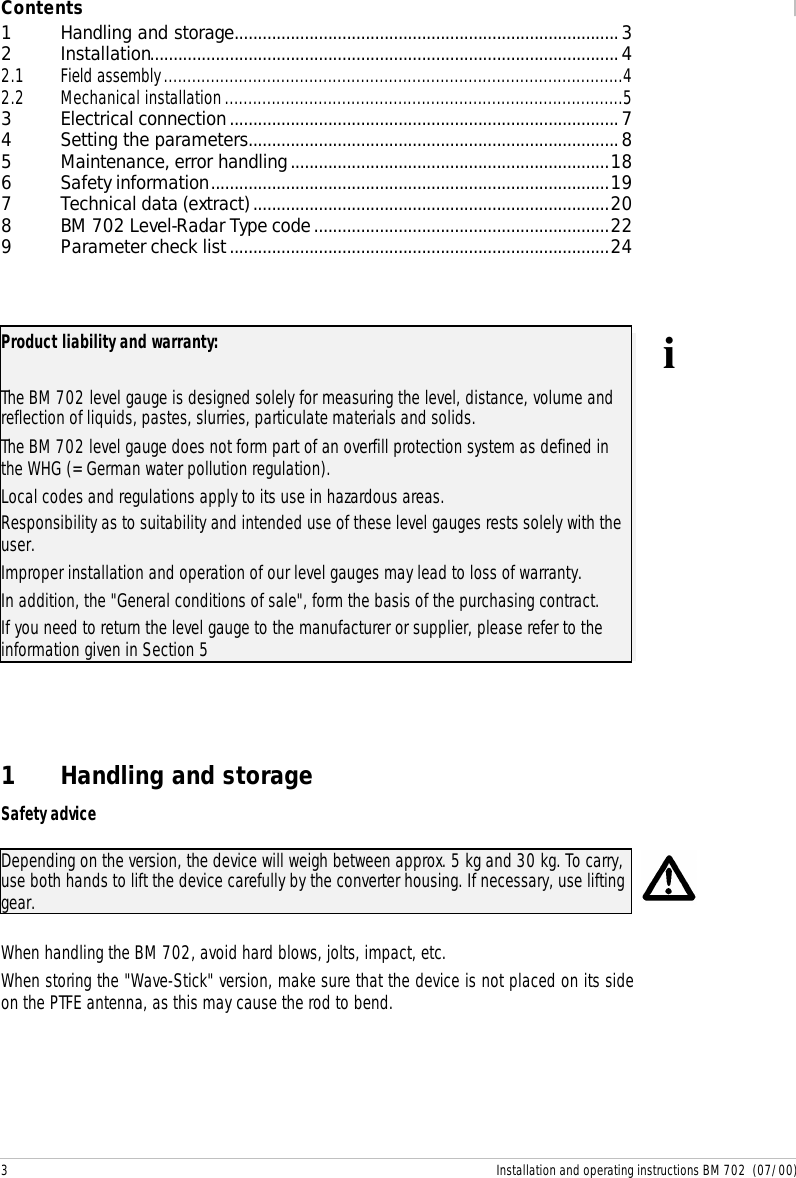
![13 Installation and operating instructions BM 702 (07/00)Function (Fct.) Input range DescriptionIf YES, for every access a 9-digit entry code on the 4keys is necessary.3.4.3 CODE 1 Enter code (RRREEEUUU)Enter the entry code foraccess lockout.3.4.4 LOCATION Enter text (8 characters) Enter a device identifier.3.5 APPLICAT.3.5.1 AUTO TANKH. Special function Automatic determination oftank height(see explanatory notes).3.5.2 EMPTY.SPEC. Select OFF/ON/RECORD Recording the profile of theempty tank (empty-tankspectrum) (see explanatorynotes).3.5.3 TIMECONST. Value 1...10...100 [s] Enter time constant formeasured-value filtering3.5.4 TRACING.VEL. Value0.01...0.50...10.00 [m/Min] Enter the maximum rate ofchange in level that canoccur in operation.3.5.5 MULT.REFL. Select NO/YES Switch the multi-reflectionidentifier on/off.3.5.6 BD-DETECT. Select NO/YES Switch the block distance(overfill) identifier on/off(see explanatory notes).3.5.7 FUNCT. FTB Select OFF/PARTIAL Select function of tankbottom tracing system (seeexplanatory notes).3.5.8 EPSILON R Enter 1.1000 ... 8.0000 Enter relative permittivity ofproduct (only for Fct. 3.5.7)3.5.9 TANKTYPE Select STORAGE T./PROC TANK Select tank type.STORAGE T. = smoothproduct surfacePROC TANK = slightlydisturbed product surfaceThe default settings are marked in the table bold.](https://usermanual.wiki/KROHNE/702.Manual/User-Guide-237556-Page-13.png)
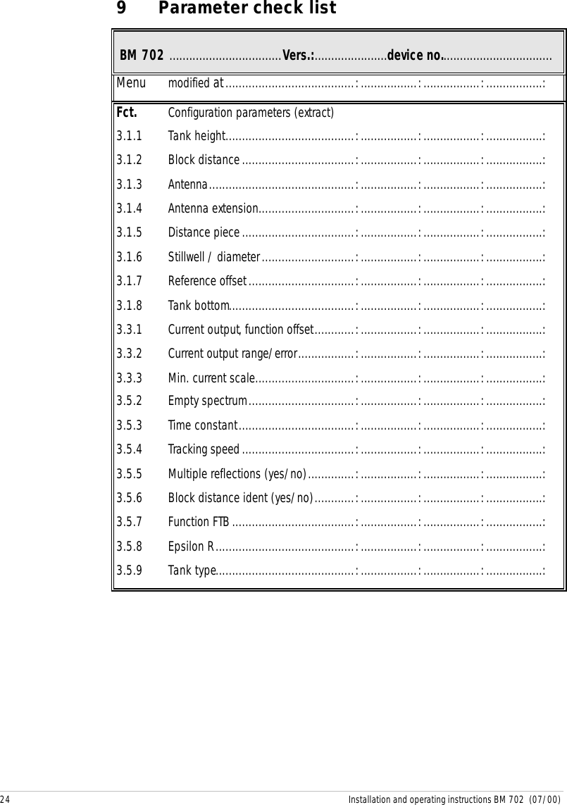
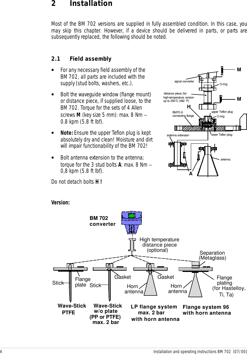
![15 Installation and operating instructions BM 702 (07/00) ++++++++++++++++++++++++++++++++Sumpnonmeasurablezonetank height (Fct. 3.1.1)Fct. 3.1.4upper reference point(top edge of tank connecting flange)block distance (Fct. 3.1.2)responsecurrent output20mAmax(Fct. 3.3.4)4min(Fct. 3.3.3)lower reference point(tank bottom / datum point)Fct. 3.1.5thresholdmeasuringmA[e.g.: 5.30 m][e.g.: 0][e.g.: 0][e.g.: 0.6 m][e.g.: 0.4 m][e.g.: 4.0 m]rangeEmpty-tank spectrumTo enable the BM 702 to identify and blank out interference signals, e.g. caused by fixedand moving tank internals, the tank profile (empty-tank spectrum) needs to be recordedonce only prior to (initial) start-up. For recording, the tank should be completely empty andall moving parts (e.g. agitators) switched on. If major interference through internals is notexpected, recording of the empty-tank spectrum can also be dispensed with, since thefactory has already carried out and stored a partial empty spectrum of the flange system.Empty-tank spectrum recording via displayAfter selecting menu item Fct. 3.5.2, press key →. The display then shows whether theempty spectrum is currently ON or OFF. Then press the ↵ key if no change is to be made, oruse the ↑ key to choose between the following options:• ON: the empty-tank spectrum is (again) switched on and taken into account formeasurements.• OFF: the empty-tank spectrum is not taken into account for measurements, butremains stored in the BM 702 and can be switched on again at a later date.• RECORD: the existing empty-tank spectrum is to be deleted and a new onerecorded.](https://usermanual.wiki/KROHNE/702.Manual/User-Guide-237556-Page-15.png)
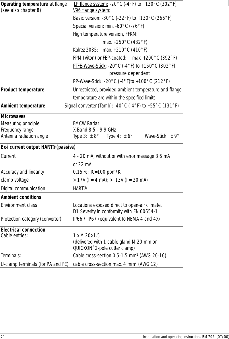
![20 Installation and operating instructions BM 702 (07/00)7 Technical data (extract)Tank height (measuring range) 0.5 to 20 m / 1.6 to 65.6 ftMeasuring accuracy (distance) from 1m/3ft: + 1cm/0.4” ; from 5m/16ft: + 0.2%Measured-value resolution 1 mm / 0.04”Rate of change in level max. 10 m/min / 32.8 ft/min (tracking speed)Connecting flangesHorn antenna/Wave-Guide DIN 2501 DN 50 to DN 200 / PN 6 to PN 64 andhigher;Shape C to DIN 2526 or othersANSI B16.5 2” to 8",Class 150 lb or 300 lb, RFWave-Stick DN 50...150 or ANSI 2”...6”, dairy DIN 11851DN 50/65/80, Tri-Clamp 2/3/4”,SMS 51/63/76 mm, G 1½"Max. allowable operating pressure -1 bar (vacuum) to max. 64 bar / 928 psig,depending on version and flange pressure rating.(see name plate)LP flange system with horn antenna, Wave-Guide or Wave-Stick without flange plate-1 bar (vacuum) to +2 bar /29 psigV96 flange system with horn antenna or Wave-Guide:Connection:nominal dia. Flange rated pressurePN 16 PN 25 PN 40 PN 64DN inches bar psig bar psig bar psig bar psig80 3 16 232 --- --- 40 580 64 928100 4 16 232 --- --- 38 551 55 797150 6 16 232 --- --- 34 493 47 681200 8 16 232 25 362 32 464 45 652Wave-Stick: max. 16 bar / 232 psig, temperature-dependent:-20 +150+100-1+1+16 46 - 0.3·T[°C] bartemperature Tpressure+232[psig] [bar]+14-14+212+302°F745 - 2.42·T[°F] psig](https://usermanual.wiki/KROHNE/702.Manual/User-Guide-237556-Page-20.png)