Juniper Networks 632 802.11abgn outdoor AP User Manual Trapeze Manual s and reference

Juniper Networks, Inc. 802.11abgn outdoor AP Trapeze Manual s and reference

Contents

Campus Connectivity MP Quick Start Guide Rev. A
Trapeze Networks, Inc.5753 W. Las Positas Blvd.Pleasanton, CA  94588Tel:  +1 925-474-2200Fax: +1 925-251-0642Toll-Free: 877-FLY-TRPZ (877-359-8779) Part Number: 730-9502-0309 Rev AFor the most current version of all documentation, go towww.trapezenetworks.comCampus Connectivity MP Quick Start Guide
Campus Connectivity MP Quick Start Guide2Trapeze NetworksThis guide provides basic hardware installation instructions for the MP-632.  Warning!Warning! Installation must be performed by qualified service personnel only. Read and follow all warning notices and instructions marked on the product or included in the documentation. Before installing the product, read the rest of this document.Warning!Waarschuwing! De installatie mag alleen worden uitgevoerd door bevoegd onderhoudspersoneel. Het is essentieel dat u kennis neemt van alle waarschuwingen en instructies aangebracht op het product zelf en/of opgenomen in de documentatie. Voordat u het product installeert, dient u dit document in zijn geheel te hebben gelezen.Warning!Warnung! Die Installation darf nur von qualifiziertem Servicepersonal vorgenommen werden. Lesen und befolgen Sie alle Warnhinweise und -anleitungen auf dem Produkt bzw. in der Dokumentation. Lesen Sie vor Installation des Produkts den restlichen Teil dieses Dokuments.Warning!Avertissement! L’installation ne peut être effectuée que par un personnel qualifié. Lisez et suivez tous les messages d’avertissement et les instructions inscrits sur le produit ou inclus dans la documentation. Avant d’installer le produit, lisez le reste de ce document.Warning!Attenzione! L’installazione deve essere effettuata unicamente da personale qualificato. Leggere e rispettare tutte le segnalazioni di attenzione e le istruzioni indicate sul prodotto o incluse nella documentazione. Prima d’installare il prodotto, leggere tutto il documento.Warning!¡Advertencia! La instalación debe realizarse exclusivamente por parte de personal de servicio cualificado. Lea y siga todas las notas de advertencia e instrucciones en el producto o la documentación. Antes de instalar el producto deberá leer la parte restante del presente documento. Warning!¡Advertencia! A instalação dever ser realizada exclusivamente por pessoal de serviço qualificado. Leia e siga todas as notas de advertência e instrucões no produto ou na documentação. Antes de instalar o produto deverá ler a parte restante do presente documento.
Campus Connectivity MP Quick Start Guide 3Trapeze NetworksWarning!Varning! Installation får endast utföras av kvalificerad servicepersonal. Läs och följ alla varningsmeddelanden och instruktioner markerade på produkten eller inkluderade i dokumenteringen. Innan produkten installeras skall resten av dessa dokument läsas.Warning!Advarsel! Installation må kun gennemføres af faglært servicepersonale. Læs, og følg alle de advarselsmeddelelser og anvisninger, der er anført på produktet eller i dokumentationen. Læs resten af dette dokument før installation af produktet.Warning!Advarsel! Installasjon skal kun utføres av kvalifisert service personell. Les og følg alle varsels meldinger og instrukssjons merkinger på produktet og i veiledningen. Les resten av denne veiledningen før produktet installeres.Warning!Varoitus! Installatie dient uitsluitend plaats te vinden door bevoegde monteurs. Lees alle waarschuwingen en instructies die op het product zijn aangegeven of in de documentatie zijn opgenomen, en volg deze op. Lees voordat u het product installeert eerst de rest van dit document.Warning!Viðvörun! Aðeins hæfir þjónustufulltrúar mega sinna uppsetningu tækjanna. Lesið og fylgið öllum viðvörunum og leiðbeiningum í þessum gögnum. Lesið restina af þessum gögnum fyrir uppsetningu.Warning!Warning!
Campus Connectivity MP Quick Start Guide4Trapeze Networks   ❑For detailed compliance information see the Trapeze Regulatory Guide located at:http://www.trapezenetworks.com/support/contact_support/. The guide can be downloaded in PDF format.Warning!Warning!Warning!Warning!Warning!Warning!
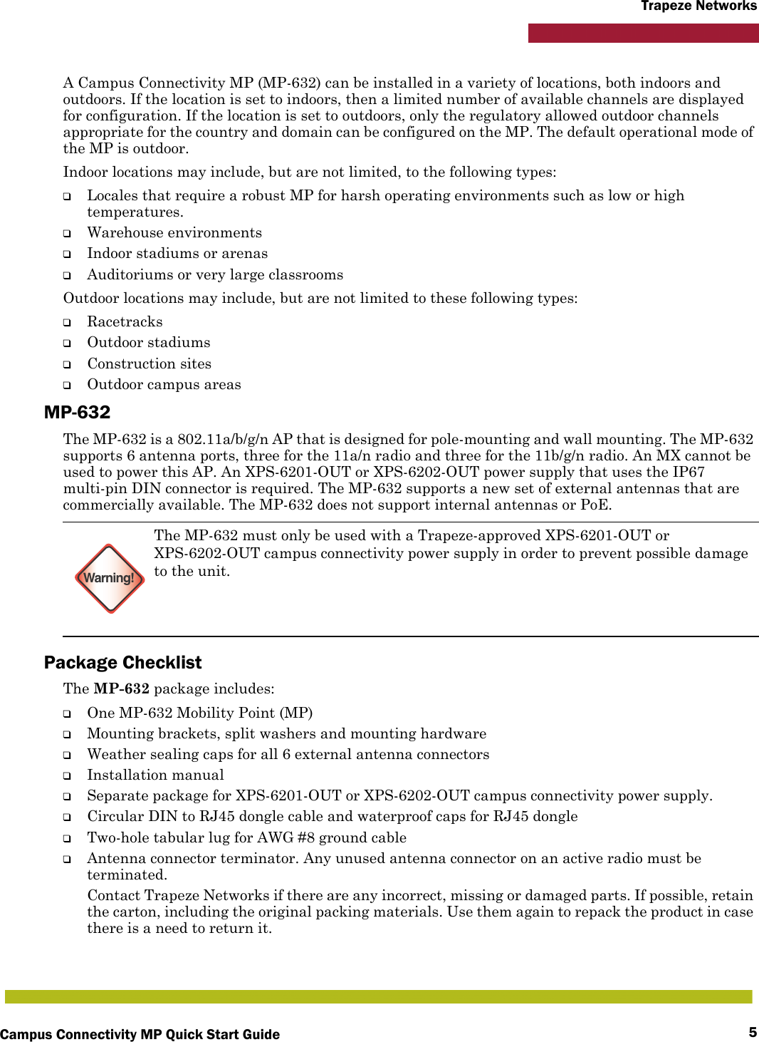
Campus Connectivity MP Quick Start Guide 5Trapeze NetworksA Campus Connectivity MP (MP-632) can be installed in a variety of locations, both indoors and outdoors. If the location is set to indoors, then a limited number of available channels are displayed for configuration. If the location is set to outdoors, only the regulatory allowed outdoor channels appropriate for the country and domain can be configured on the MP. The default operational mode of the MP is outdoor.Indoor locations may include, but are not limited, to the following types:❑Locales that require a robust MP for harsh operating environments such as low or high temperatures.❑Warehouse environments❑Indoor stadiums or arenas❑Auditoriums or very large classroomsOutdoor locations may include, but are not limited to these following types:❑Racetracks❑Outdoor stadiums❑Construction sites❑Outdoor campus areasMP-632The MP-632 is a 802.11a/b/g/n AP that is designed for pole-mounting and wall mounting. The MP-632 supports 6 antenna ports, three for the 11a/n radio and three for the 11b/g/n radio. An MX cannot be used to power this AP. An XPS-6201-OUT or XPS-6202-OUT power supply that uses the IP67 multi-pin DIN connector is required. The MP-632 supports a new set of external antennas that are commercially available. The MP-632 does not support internal antennas or PoE.Package ChecklistThe MP-632 package includes:❑One MP-632 Mobility Point (MP)❑Mounting brackets, split washers and mounting hardware❑Weather sealing caps for all 6 external antenna connectors❑Installation manual❑Separate package for XPS-6201-OUT or XPS-6202-OUT campus connectivity power supply.❑Circular DIN to RJ45 dongle cable and waterproof caps for RJ45 dongle❑Two-hole tabular lug for AWG #8 ground cable❑Antenna connector terminator. Any unused antenna connector on an active radio must be terminated.Contact Trapeze Networks if there are any incorrect, missing or damaged parts. If possible, retain the carton, including the original packing materials. Use them again to repack the product in case there is a need to return it.Warning!The MP-632 must only be used with a Trapeze-approved XPS-6201-OUT or XPS-6202-OUT campus connectivity power supply in order to prevent possible damage to the unit.
Campus Connectivity MP Quick Start Guide6Trapeze NetworksInstalling and Connecting an MPInstallation Requirements and RecommendationsFor best results, follow these requirements and recommendations before installing a MP-632.RingMaster Network Plan and Work OrdersIf you are using RingMaster to plan your Trapeze Networks Mobility System installation, you might want to create and verify a network plan for the entire Trapeze network installation and generate an MP work order, before installing MP access points. A network plan and the MP work orders generated from it provide the following information about MP access point installation and configuration:❑Number of MPs required for adequate WLAN capacity in each coverage area❑Detailed installation location for each MP❑Settings for all MP access points in the WLANMX Appliance RecommendationTrapeze Networks recommends that you install and configure the MX before installing an MP. If the MX is already installed and configured for the MPs, you can immediately verify the cable connection(s) when you plug the cable(s) into the MP.Weather ConditionsWhen planning a MP-632 installation, you must take into account any extreme weather conditions that are known to affect your location. Consider the following factors:Temperature Operating an MP in temperatures outside of the supported range may cause the unit to fail. The MP-632 is tested for an ambient operating temperature range of -40°C to +55°C.Wind VelocityYou must consider the known maximum wind velocity and direction at the site and be sure that any supporting structure, such as a pole, mast, or tower, is built to withstand this force. The MP-632 can operate in winds up to 90 MPH and survive higher wind speeds up to 125 MPH. Note:Before installing an MP, you might need to generate a network plan and an MP work order with RingMaster. (See RingMaster Network Plan and Work Orders below.)Warning!The MP-632 is designed to receive power only from a Trapeze-provided power injector.
Campus Connectivity MP Quick Start Guide 7Trapeze NetworksLightningThe MP-632 has built-in lightning protection. However, you should make sure that the unit, any supporting structure, and cables are all properly grounded. Additional protection using lightning rods, lightning arrestors, or surge suppressors may also be employed. RainThe MP-632 weatherproof enclosure is designed to protect against dust, rain, and water jets.Snow and IceFalling snow, like rain, has no significant effect on the radio signal. However, a build up of snow or ice on antennas may cause a degradation in performance. In this case, the snow or ice has to be cleared from the antennas to restore proper operation of the unit.Ethernet CablingWhen you have determined a suitable location for the MP, you must plan a cable route from the MP to the power injector module. Consider these points:❑The Ethernet cable length should never be longer than 100 m (328 ft) over CAT5, CAT5e, or CAT6 cable.❑Determine a building entry point for the cable.❑Determine if conduits, bracing, or other structures are required for safety or protection of the cable.❑For lightning protection at the power injector end of the cable, consider using a lightning arrestor immediately before the cable enters the building.GroundingIt is important that the MP-632 unit, cable, lightning arrestor, and any supporting structures are properly grounded. Be sure that grounding is available and that it meets local and national electrical codes. The MP-632 includes two grounding screws and a tubular lug for attaching a crimped ground wire.MP Radio Safety AdvisoriesWhen you enable the MP radio(s) as part of MX configuration, the radios are able to receive and transmit radio frequency energy as soon as you connect the MP to the MX, either directly or through the network. Radio Frequency ExposureFederal Communications Commission (FCC) Docket 96-8 for Spread Spectrum Transmitters specifies a safety standard for human exposure to radio frequency electromagnetic energy emitted by FCC-certified equipment. When used with the proper antennas (shipped in the product), Trapeze Networks MP access point products meet the uncontrolled environmental limits found in OET-65 and ANSI C95.1-1991. Proper installation of the MP access point according to the instructions in this manual will result in user exposure that is below the FCC recommended limits.
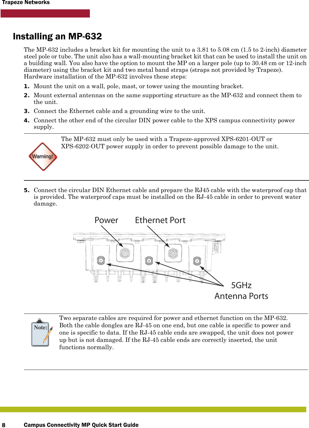
Campus Connectivity MP Quick Start Guide8Trapeze NetworksInstalling an MP-632The MP-632 includes a bracket kit for mounting the unit to a 3.81 to 5.08 cm (1.5 to 2-inch) diameter steel pole or tube. The unit also has a wall-mounting bracket kit that can be used to install the unit on a building wall. You also have the option to mount the MP on a larger pole (up to 30.48 cm or 12-inch diameter) using the bracket kit and two metal band straps (straps not provided by Trapeze). Hardware installation of the MP-632 involves these steps:1. Mount the unit on a wall, pole, mast, or tower using the mounting bracket.2. Mount external antennas on the same supporting structure as the MP-632 and connect them to the unit.3. Connect the Ethernet cable and a grounding wire to the unit.4. Connect the other end of the circular DIN power cable to the XPS campus connectivity power supply.5. Connect the circular DIN Ethernet cable and prepare the RJ45 cable with the waterproof cap that is provided. The waterproof caps must be installed on the RJ-45 cable in order to prevent water damage. Warning!The MP-632 must only be used with a Trapeze-approved XPS-6201-OUT or XPS-6202-OUT power supply in order to prevent possible damage to the unit.   Note:Two separate cables are required for power and ethernet function on the MP-632.Both the cable dongles are RJ-45 on one end, but one cable is specific to power andone is specific to data. If the RJ-45 cable ends are swapped, the unit does not powerup but is not damaged. If the RJ-45 cable ends are correctly inserted, the unitfunctions normally. 5GHzAntenna PortsPower Ethernet Port
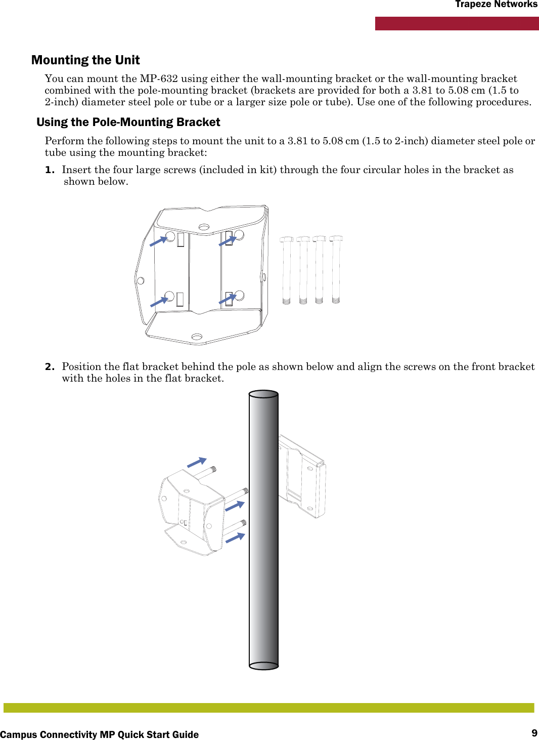
Campus Connectivity MP Quick Start Guide 9Trapeze NetworksMounting the UnitYou can mount the MP-632 using either the wall-mounting bracket or the wall-mounting bracket combined with the pole-mounting bracket (brackets are provided for both a 3.81 to 5.08 cm (1.5 to 2-inch) diameter steel pole or tube or a larger size pole or tube). Use one of the following procedures.Using the Pole-Mounting BracketPerform the following steps to mount the unit to a 3.81 to 5.08 cm (1.5 to 2-inch) diameter steel pole or tube using the mounting bracket:1. Insert the four large screws (included in kit) through the four circular holes in the bracket as shown below.2. Position the flat bracket behind the pole as shown below and align the screws on the front bracket with the holes in the flat bracket.
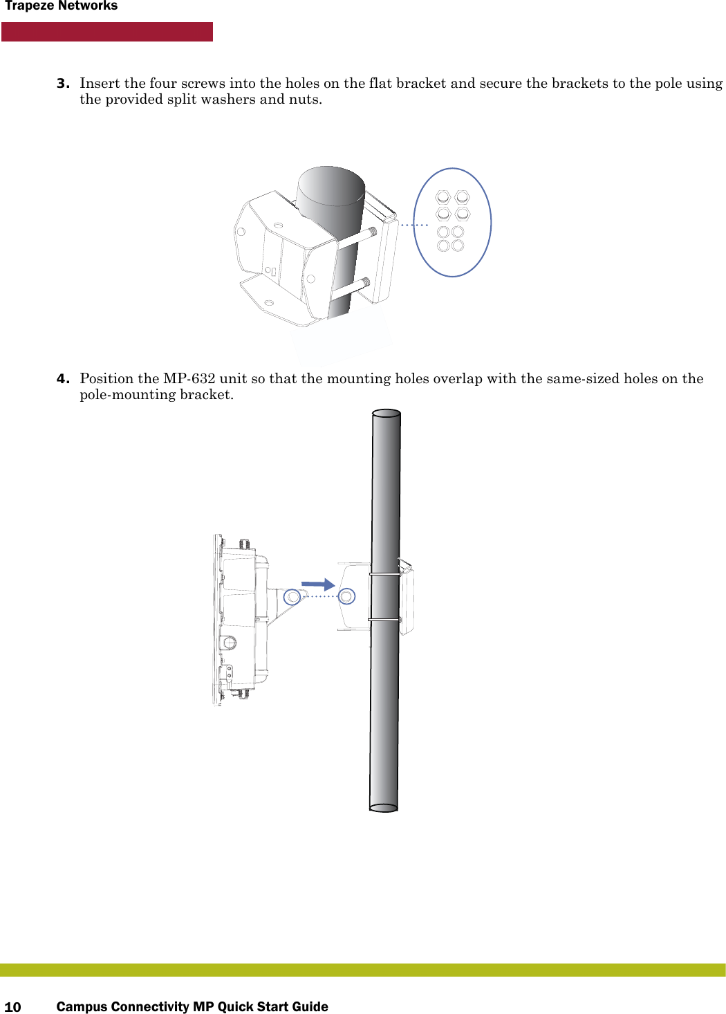
Campus Connectivity MP Quick Start Guide10Trapeze Networks3. Insert the four screws into the holes on the flat bracket and secure the brackets to the pole using the provided split washers and nuts.4. Position the MP-632 unit so that the mounting holes overlap with the same-sized holes on the pole-mounting bracket.
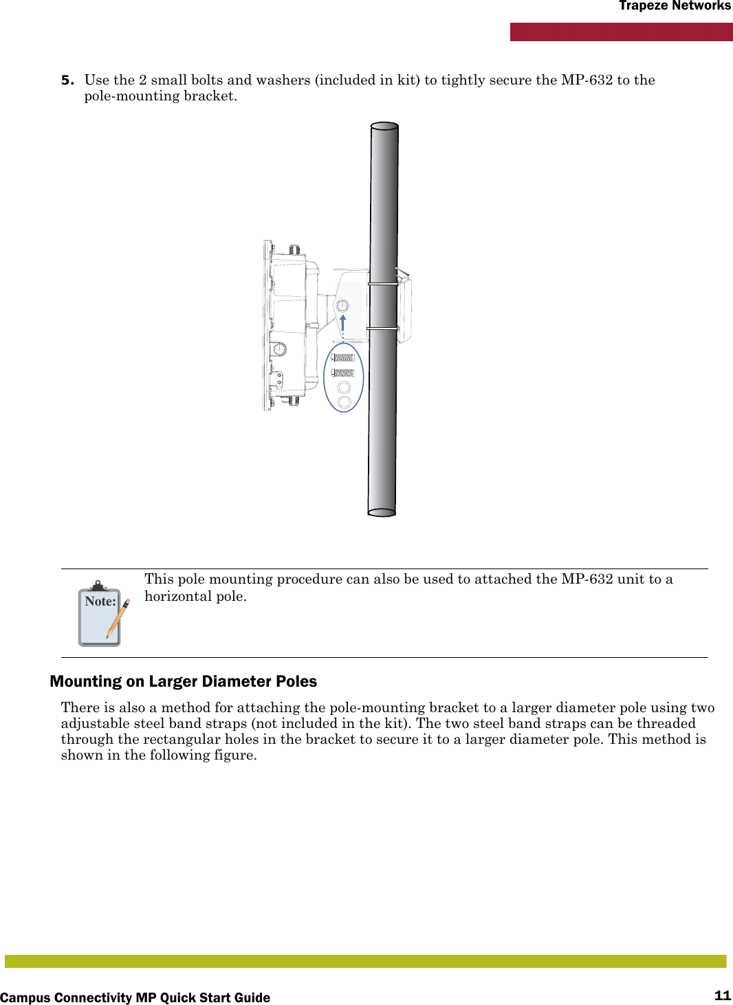
Campus Connectivity MP Quick Start Guide 11Trapeze Networks5. Use the 2 small bolts and washers (included in kit) to tightly secure the MP-632 to the pole-mounting bracket.Mounting on Larger Diameter PolesThere is also a method for attaching the pole-mounting bracket to a larger diameter pole using two adjustable steel band straps (not included in the kit). The two steel band straps can be threaded through the rectangular holes in the bracket to secure it to a larger diameter pole. This method is shown in the following figure.Note:This pole mounting procedure can also be used to attached the MP-632 unit to a horizontal pole.
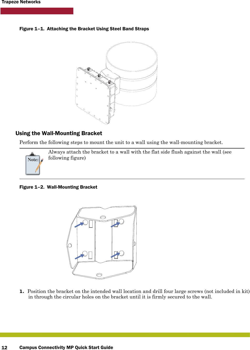
Campus Connectivity MP Quick Start Guide12Trapeze NetworksFigure 1–1.  Attaching the Bracket Using Steel Band Straps   Using the Wall-Mounting BracketPerform the following steps to mount the unit to a wall using the wall-mounting bracket.Figure 1–2.  Wall-Mounting Bracket   1. Position the bracket on the intended wall location and drill four large screws (not included in kit) in through the circular holes on the bracket until it is firmly secured to the wall.Note:Always attach the bracket to a wall with the flat side flush against the wall (see following figure)
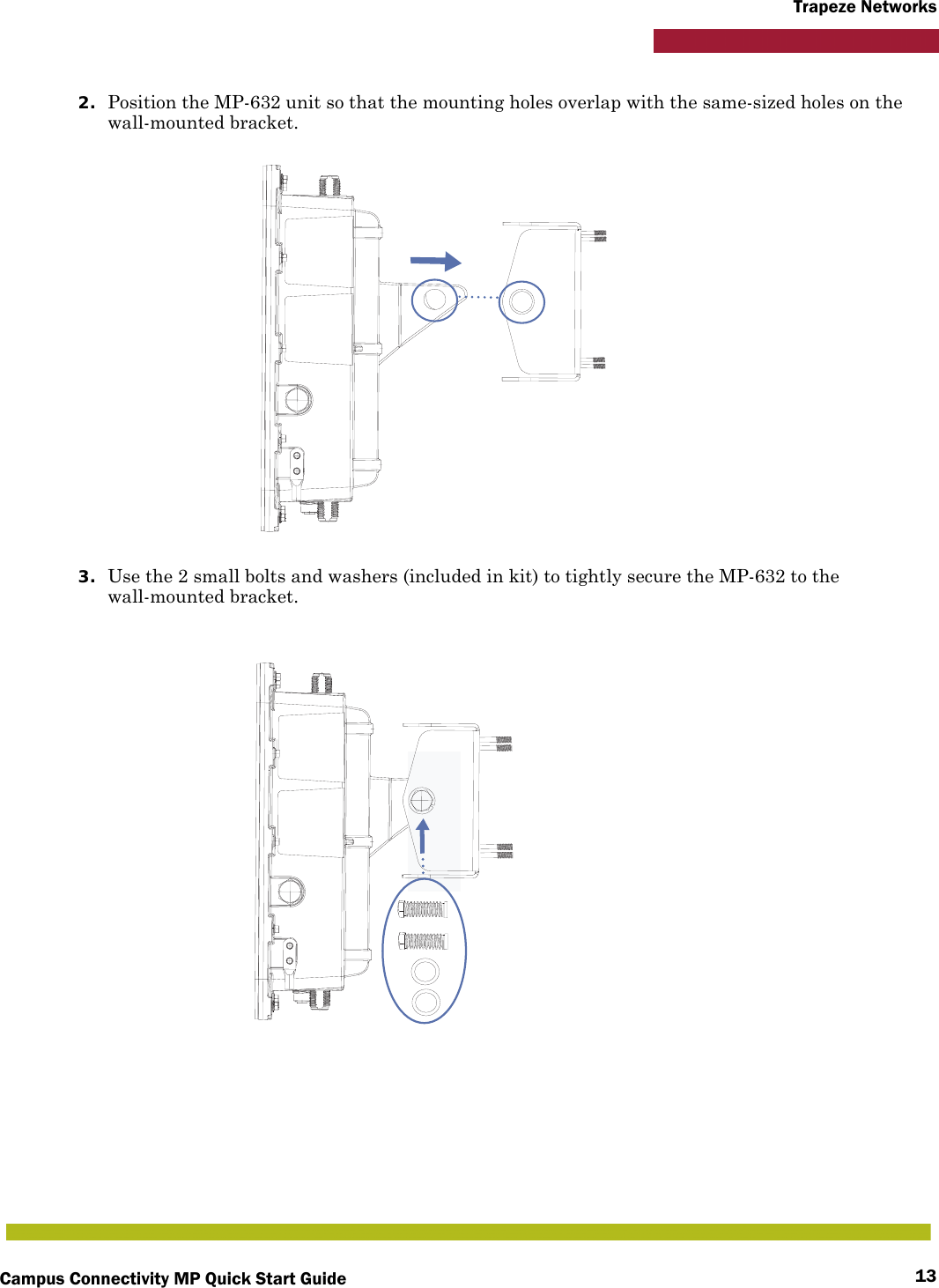
Campus Connectivity MP Quick Start Guide 13Trapeze Networks2. Position the MP-632 unit so that the mounting holes overlap with the same-sized holes on the wall-mounted bracket. 3. Use the 2 small bolts and washers (included in kit) to tightly secure the MP-632 to the wall-mounted bracket.
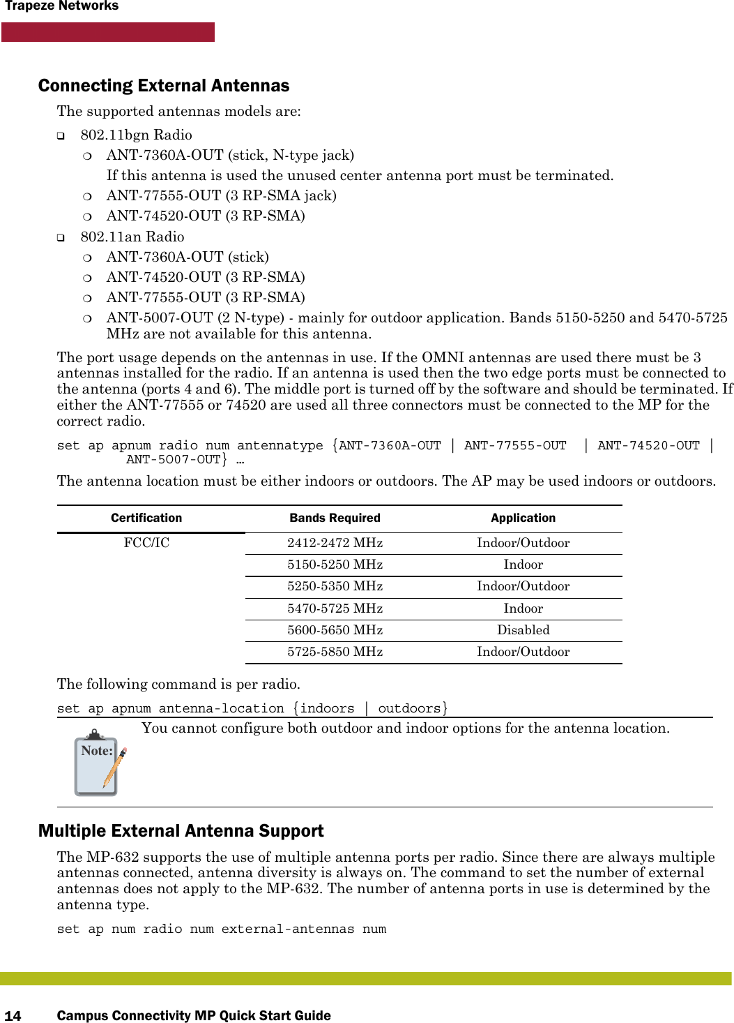
Campus Connectivity MP Quick Start Guide14Trapeze NetworksConnecting External AntennasThe supported antennas models are:❑802.11bgn Radio❍ANT-7360A-OUT (stick, N-type jack)If this antenna is used the unused center antenna port must be terminated.❍ANT-77555-OUT (3 RP-SMA jack)❍ANT-74520-OUT (3 RP-SMA)❑802.11an Radio❍ANT-7360A-OUT (stick)❍ANT-74520-OUT (3 RP-SMA)❍ANT-77555-OUT (3 RP-SMA)❍ANT-5007-OUT (2 N-type) - mainly for outdoor application. Bands 5150-5250 and 5470-5725 MHz are not available for this antenna.The port usage depends on the antennas in use. If the OMNI antennas are used there must be 3 antennas installed for the radio. If an antenna is used then the two edge ports must be connected to the antenna (ports 4 and 6). The middle port is turned off by the software and should be terminated. If either the ANT-77555 or 74520 are used all three connectors must be connected to the MP for the correct radio.set ap apnum radio num antennatype {ANT-7360A-OUT | ANT-77555-OUT  | ANT-74520-OUT | ANT-5O07-OUT} …The antenna location must be either indoors or outdoors. The AP may be used indoors or outdoors. The following command is per radio.set ap apnum antenna-location {indoors | outdoors}Multiple External Antenna SupportThe MP-632 supports the use of multiple antenna ports per radio. Since there are always multiple antennas connected, antenna diversity is always on. The command to set the number of external antennas does not apply to the MP-632. The number of antenna ports in use is determined by the antenna type.set ap num radio num external-antennas numCertification Bands Required ApplicationFCC/IC 2412-2472 MHz  Indoor/Outdoor5150-5250 MHz Indoor5250-5350 MHz Indoor/Outdoor5470-5725 MHz Indoor5600-5650 MHz Disabled5725-5850 MHz Indoor/OutdoorNote:You cannot configure both outdoor and indoor options for the antenna location.
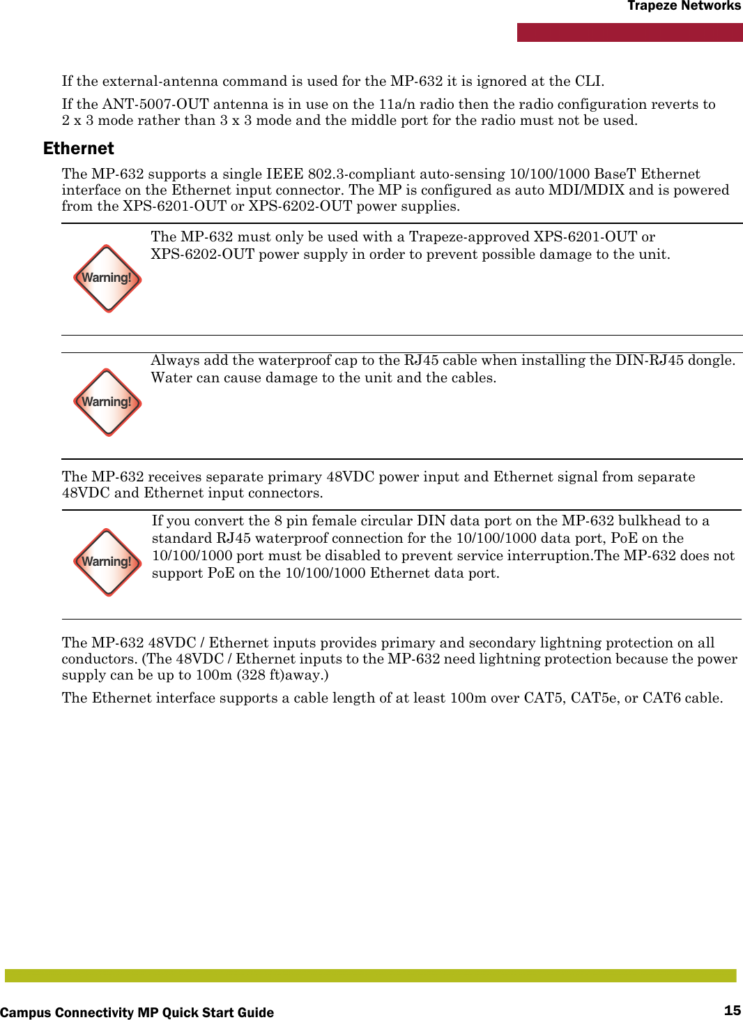
Campus Connectivity MP Quick Start Guide 15Trapeze NetworksIf the external-antenna command is used for the MP-632 it is ignored at the CLI.If the ANT-5007-OUT antenna is in use on the 11a/n radio then the radio configuration reverts to 2 x 3 mode rather than 3 x 3 mode and the middle port for the radio must not be used.EthernetThe MP-632 supports a single IEEE 802.3-compliant auto-sensing 10/100/1000 BaseT Ethernet interface on the Ethernet input connector. The MP is configured as auto MDI/MDIX and is powered from the XPS-6201-OUT or XPS-6202-OUT power supplies.The MP-632 receives separate primary 48VDC power input and Ethernet signal from separate 48VDC and Ethernet input connectors.The MP-632 48VDC / Ethernet inputs provides primary and secondary lightning protection on all conductors. (The 48VDC / Ethernet inputs to the MP-632 need lightning protection because the power supply can be up to 100m (328 ft)away.)The Ethernet interface supports a cable length of at least 100m over CAT5, CAT5e, or CAT6 cable.Warning!The MP-632 must only be used with a Trapeze-approved XPS-6201-OUT or XPS-6202-OUT power supply in order to prevent possible damage to the unit.Warning!Always add the waterproof cap to the RJ45 cable when installing the DIN-RJ45 dongle. Water can cause damage to the unit and the cables.Warning!If you convert the 8 pin female circular DIN data port on the MP-632 bulkhead to a standard RJ45 waterproof connection for the 10/100/1000 data port, PoE on the 10/100/1000 port must be disabled to prevent service interruption.The MP-632 does not support PoE on the 10/100/1000 Ethernet data port.
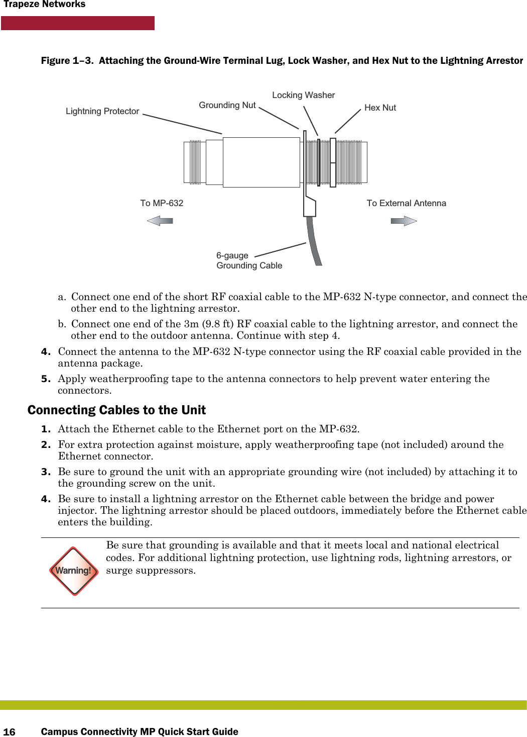
Campus Connectivity MP Quick Start Guide16Trapeze NetworksFigure 1–3.  Attaching the Ground-Wire Terminal Lug, Lock Washer, and Hex Nut to the Lightning Arrestor      a. Connect one end of the short RF coaxial cable to the MP-632 N-type connector, and connect the other end to the lightning arrestor.b. Connect one end of the 3m (9.8 ft) RF coaxial cable to the lightning arrestor, and connect the other end to the outdoor antenna. Continue with step 4.4. Connect the antenna to the MP-632 N-type connector using the RF coaxial cable provided in the antenna package.5. Apply weatherproofing tape to the antenna connectors to help prevent water entering the connectors.Connecting Cables to the Unit1. Attach the Ethernet cable to the Ethernet port on the MP-632. 2. For extra protection against moisture, apply weatherproofing tape (not included) around the Ethernet connector.3. Be sure to ground the unit with an appropriate grounding wire (not included) by attaching it to the grounding screw on the unit.4. Be sure to install a lightning arrestor on the Ethernet cable between the bridge and power injector. The lightning arrestor should be placed outdoors, immediately before the Ethernet cable enters the building.Warning!Be sure that grounding is available and that it meets local and national electrical codes. For additional lightning protection, use lightning rods, lightning arrestors, or surge suppressors.To External AntennaTo MP-6326-gaugeGrounding CableGrounding NutLocking WasherHex NutLightning Protector
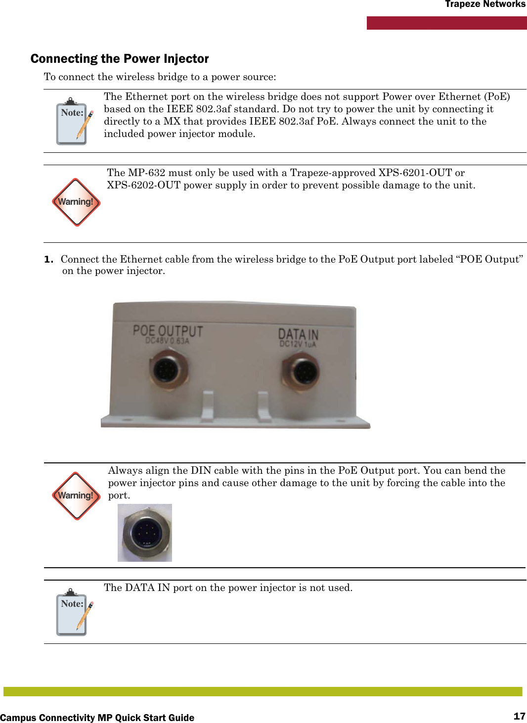
Campus Connectivity MP Quick Start Guide 17Trapeze NetworksConnecting the Power InjectorTo connect the wireless bridge to a power source:1. Connect the Ethernet cable from the wireless bridge to the PoE Output port labeled “POE Output” on the power injector.Note:The Ethernet port on the wireless bridge does not support Power over Ethernet (PoE) based on the IEEE 802.3af standard. Do not try to power the unit by connecting it directly to a MX that provides IEEE 802.3af PoE. Always connect the unit to the included power injector module.Warning!The MP-632 must only be used with a Trapeze-approved XPS-6201-OUT or XPS-6202-OUT power supply in order to prevent possible damage to the unit.Warning!Always align the DIN cable with the pins in the PoE Output port. You can bend the power injector pins and cause other damage to the unit by forcing the cable into the port.Note:The DATA IN port on the power injector is not used.
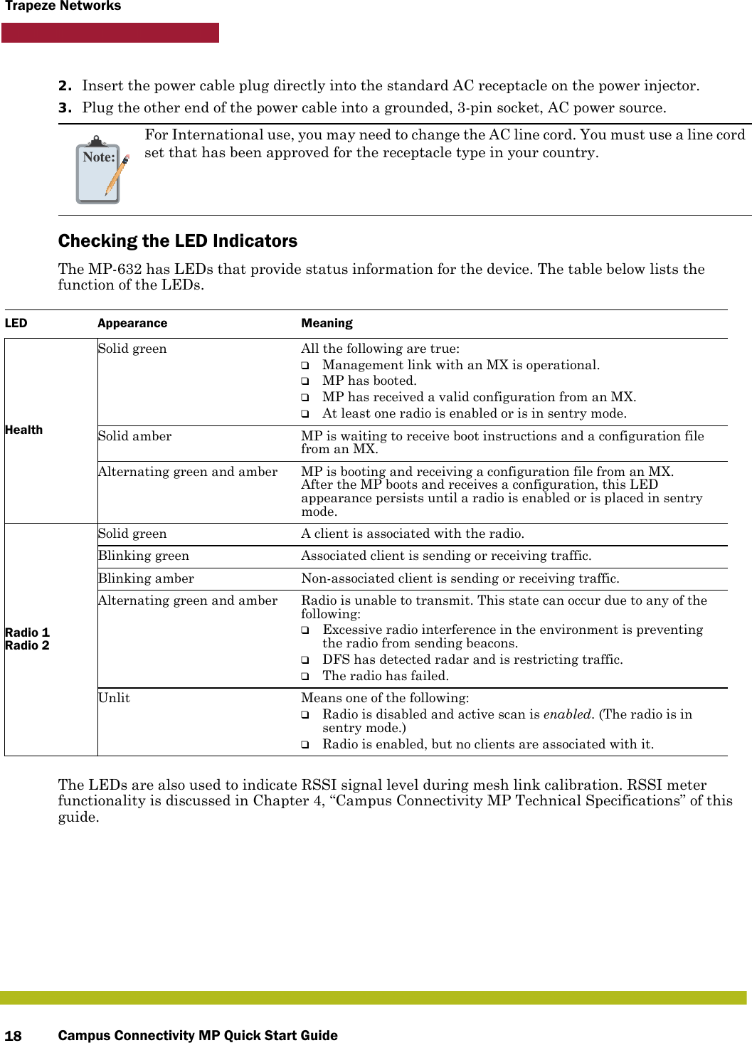
Campus Connectivity MP Quick Start Guide18Trapeze Networks2. Insert the power cable plug directly into the standard AC receptacle on the power injector.3. Plug the other end of the power cable into a grounded, 3-pin socket, AC power source.Checking the LED IndicatorsThe MP-632 has LEDs that provide status information for the device. The table below lists the function of the LEDs. The LEDs are also used to indicate RSSI signal level during mesh link calibration. RSSI meter functionality is discussed in Chapter 4, “Campus Connectivity MP Technical Specifications” of this guide.Note:For International use, you may need to change the AC line cord. You must use a line cord set that has been approved for the receptacle type in your country.LED Appearance MeaningHealthSolid green All the following are true:❑Management link with an MX is operational.❑MP has booted.❑MP has received a valid configuration from an MX.❑At least one radio is enabled or is in sentry mode.Solid amber MP is waiting to receive boot instructions and a configuration file from an MX. Alternating green and amber MP is booting and receiving a configuration file from an MX. After the MP boots and receives a configuration, this LED appearance persists until a radio is enabled or is placed in sentry mode.Radio 1 Radio 2Solid green A client is associated with the radio.Blinking green Associated client is sending or receiving traffic.Blinking amber Non-associated client is sending or receiving traffic.Alternating green and amber Radio is unable to transmit. This state can occur due to any of the following:❑Excessive radio interference in the environment is preventing the radio from sending beacons.❑DFS has detected radar and is restricting traffic.❑The radio has failed.Unlit Means one of the following:❑Radio is disabled and active scan is enabled. (The radio is in sentry mode.)❑Radio is enabled, but no clients are associated with it.
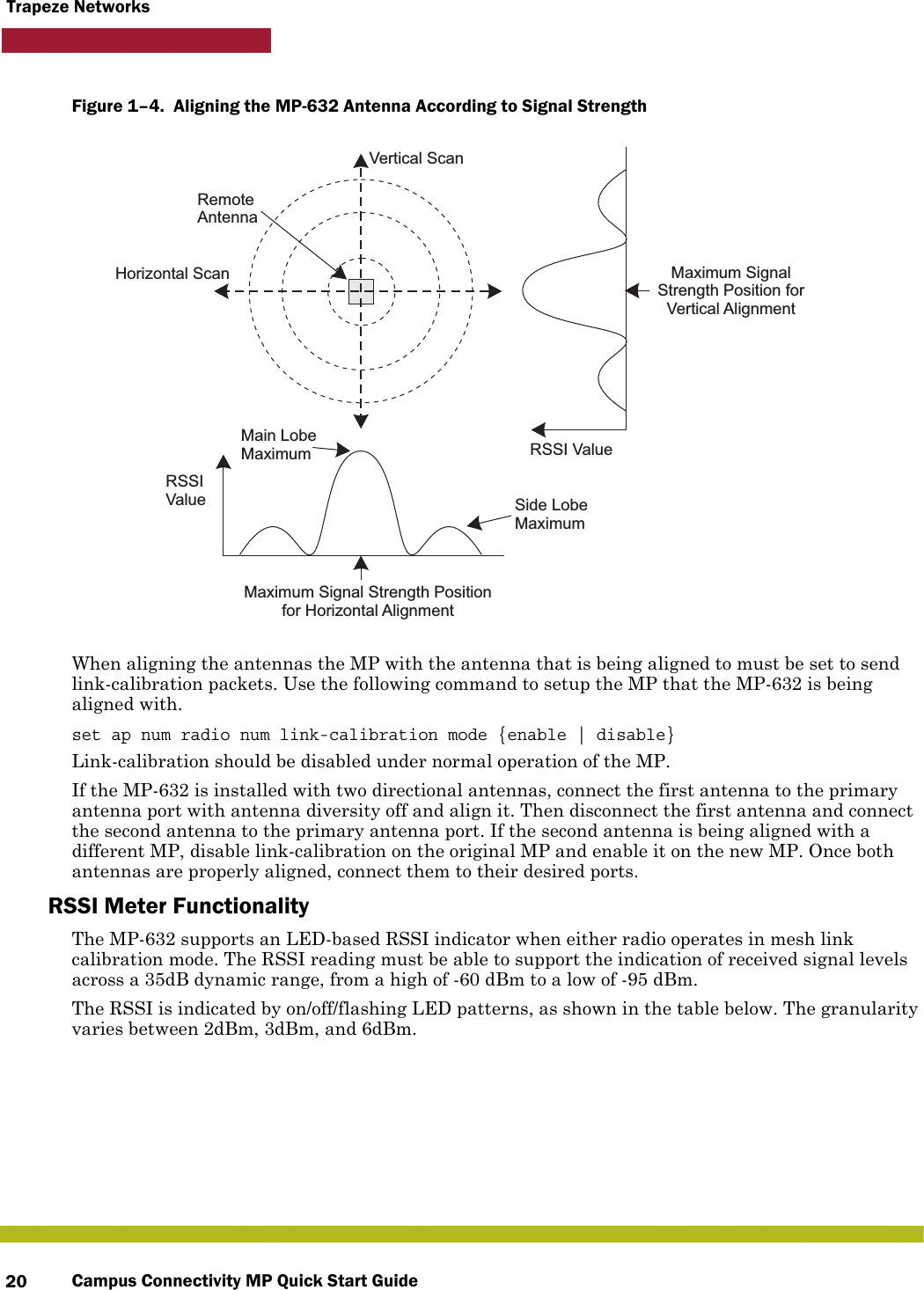
Campus Connectivity MP Quick Start Guide 19Trapeze NetworksAligning Antennas for Bridge or Mesh LinksIf you are installing MP-632 units for wireless bridge or Mesh Services operation, after the units have been mounted, connected, and the radios are operating, the antennas must be accurately aligned to ensure optimum performance on the bridge or mesh links. This alignment process is particularly important for long-range point-to-point links. In a point-to-multipoint configuration, the Mesh Portal AP uses an omnidirectional or sector antenna, which does not require alignment, but Mesh APs still need to be correctly aligned with the Mesh Portal antenna.❑Point-to-Point Configurations – In a point-to-point configuration, the alignment process requires two people at each end of the link. The use of cell phones or two-way radio communication may help with coordination. To start, you can just point the antennas at each other, using binoculars or a compass to set the general direction. For accurate alignment, monitor the RSSI’s LED indicator as you move the antenna horizontally and vertically.❑Point-to-Multipoint Configurations – In a point-to-multipoint configuration all Mesh APs must be aligned with the Mesh Portal antenna. The alignment process is the same as for point-to-point links, but only the Mesh AP end of the link requires the alignment.The LEDs are viewed right to left as you look at the back of the MP. The range from 1 to 12 will cover the signal range to accurately align the antenna. The signal strength LEDs indicate the received radio signal strength for a particular bridge link. The more LEDs that turn on, the stronger the signal. (RSSI level 1 should equate to the lowest useful signal). Alternatively, you can monitor the Receive Signal Strength Indicator (RSSI) value directly from the management interface. The higher the RSSI value, the stronger the signal.When you move the antenna during alignment, the radio signal from the remote antenna can be seen to have a strong central main lobe and smaller side lobes. The object of the alignment process is to set the antenna so that it is receiving the strongest signal from the central main lobe.
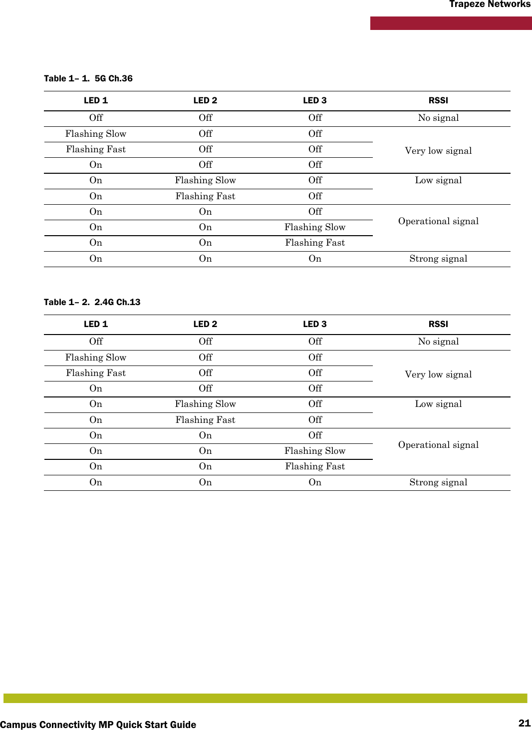
Campus Connectivity MP Quick Start Guide20Trapeze NetworksFigure 1–4.  Aligning the MP-632 Antenna According to Signal Strength   When aligning the antennas the MP with the antenna that is being aligned to must be set to send link-calibration packets. Use the following command to setup the MP that the MP-632 is being aligned with.set ap num radio num link-calibration mode {enable | disable}Link-calibration should be disabled under normal operation of the MP.If the MP-632 is installed with two directional antennas, connect the first antenna to the primary antenna port with antenna diversity off and align it. Then disconnect the first antenna and connect the second antenna to the primary antenna port. If the second antenna is being aligned with a different MP, disable link-calibration on the original MP and enable it on the new MP. Once both antennas are properly aligned, connect them to their desired ports.RSSI Meter FunctionalityThe MP-632 supports an LED-based RSSI indicator when either radio operates in mesh link calibration mode. The RSSI reading must be able to support the indication of received signal levels across a 35dB dynamic range, from a high of -60 dBm to a low of -95 dBm.The RSSI is indicated by on/off/flashing LED patterns, as shown in the table below. The granularity varies between 2dBm, 3dBm, and 6dBm.Main LobeMaximumHorizontal ScanVertical ScanRSSIValue Side LobeMaximumRSSI ValueRemoteAntennaMaximum Signal Strength Positionfor Horizontal AlignmentMaximum SignalStrength Position forVertical Alignment
Campus Connectivity MP Quick Start Guide 21Trapeze NetworksTable 1– 1.  5G Ch.36LED 1 LED 2 LED 3 RSSIOff Off Off No signalFlashing Slow Off OffVery low signalFlashing Fast Off OffOn Off OffOn Flashing Slow Off Low signalOn Flashing Fast OffOn On OffOperational signalOn On Flashing SlowOn On Flashing FastOn On On Strong signalTable 1– 2.  2.4G Ch.13LED 1 LED 2 LED 3 RSSIOff Off Off No signalFlashing Slow Off OffVery low signalFlashing Fast Off OffOn Off OffOn Flashing Slow Off Low signalOn Flashing Fast OffOn On OffOperational signalOn On Flashing SlowOn On Flashing FastOn On On Strong signal
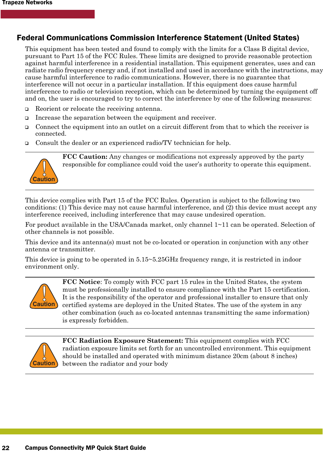
Campus Connectivity MP Quick Start Guide22Trapeze NetworksFederal Communications Commission Interference Statement (United States)This equipment has been tested and found to comply with the limits for a Class B digital device, pursuant to Part 15 of the FCC Rules. These limits are designed to provide reasonable protection against harmful interference in a residential installation. This equipment generates, uses and can radiate radio frequency energy and, if not installed and used in accordance with the instructions, may cause harmful interference to radio communications. However, there is no guarantee that interference will not occur in a particular installation. If this equipment does cause harmful interference to radio or television reception, which can be determined by turning the equipment off and on, the user is encouraged to try to correct the interference by one of the following measures:❑Reorient or relocate the receiving antenna.❑Increase the separation between the equipment and receiver.❑Connect the equipment into an outlet on a circuit different from that to which the receiver is connected.❑Consult the dealer or an experienced radio/TV technician for help.This device complies with Part 15 of the FCC Rules. Operation is subject to the following two conditions: (1) This device may not cause harmful interference, and (2) this device must accept any interference received, including interference that may cause undesired operation.For product available in the USA/Canada market, only channel 1~11 can be operated. Selection of other channels is not possible.This device and its antenna(s) must not be co-located or operation in conjunction with any other antenna or transmitter.This device is going to be operated in 5.15~5.25GHz frequency range, it is restricted in indoor environment only.!CautionFCC Caution: Any changes or modifications not expressly approved by the party responsible for compliance could void the user’s authority to operate this equipment. !CautionFCC Notice: To comply with FCC part 15 rules in the United States, the system must be professionally installed to ensure compliance with the Part 15 certification. It is the responsibility of the operator and professional installer to ensure that only certified systems are deployed in the United States. The use of the system in any other combination (such as co-located antennas transmitting the same information) is expressly forbidden.!CautionFCC Radiation Exposure Statement: This equipment complies with FCC radiation exposure limits set forth for an uncontrolled environment. This equipment should be installed and operated with minimum distance 20cm (about 8 inches) between the radiator and your body
Campus Connectivity MP Quick Start Guide 23Trapeze NetworksCanadian Department of Communications Industry Canada Notice (Canada)This digital apparatus meets the requirements of Canadian Interference-Causing Equipment Regulation RSS-210.This Class B digital apparatus complies with Canadian ICES-003.Operation is subject to the following two conditions: 1. This device may not cause interference.2. This device must accept any interference, including interference that may cause undesired operation of the device. Cet appareil numérique de la classe B conforme á la norme NMB-003 du Canada.Country Code Statement: For product available in the USA/Canada market, only channel 1~11 can be operated. Selection of other channels is not possible.This device and its antenna(s) must not be co-located or operation in conjunction with any other antenna or transmitter.To reduce potential radio interference to other users, the antenna type and its gain should be so chosen that the equivalent isotropically radiated power (e.i.r.p) is not more than that permitted for successful communication.This device has been designed to operate with the antennas listed below, and having a maximum gain of [23.5] dB. Antennas not included in this list or having a gain greater than [23.5] dB are strictly prohibited for use with this device. The required antenna impedance is 50 ohms.The device could automatically discontinue transmission in case of absence of information to transmit, or operational failure. Note that this is not intended to prohibit transmission of control or signaling information or the use of repetitive codes where required by the technology.The device for the band 5150-5250 MHz is only for indoor usage to reduce potential for harmful interference to co-channel mobile satellite systems.The maximum antenna gain permitted (for devices in the band 5725-5825 MHz) to comply with the e.i.r.p. limits specified for point-to-point and non point-to-point operation as appropriate, as stated in section A9.2(3).The maximum antenna gain permitted (for devices in the bands 5250-5350 MHz and 5470-5725 MHz) to comply with the e.i.r.p. limit. High-power radars are allocated as primary users (meaning they have priority) of the bands 5250-5350 MHz and 5650-5850 MHz and these radars could cause interference and/or damage to LE-LAN devices.!CautionIC Radiation Exposure Statement: This equipment complies with IC RSS-102 radiation exposure limits set forth for an uncontrolled environment. This equipment should be installed and operated with minimum distance 20cm (about 8 inches) between the radiator & your body.
Campus Connectivity MP Quick Start Guide24Trapeze Networks
Trapeze Networks© 2010 Trapeze Networks, Inc. All rights reserved. Trapeze Networks, the Trapeze Networks logodesign, Trapeze Smart Mobile, Trapeze Networks Mobility System Software, RingMaster,Mobility System, Mobility Exchange, Mobility Point, SafetyNet, MX, and MP are registeredtrademarks and/or registered service marks of Trapeze Networks, Inc. Trapeze, Smart Mobile,Mobility System Software, Mobility Domain, SmartPass, NonStop Wireless, Medical GradeMobility and Wireless Without Limits are trademarks and/or service marks of TrapezeNetworks, Inc. All other products and services are trademarks, registered trademarks, servicemarks, or registered service marks of their respective owners.All statements, specifications, recommendations, and technical information are current orplanned as of the publication of this document. They are reliable as of the time of this writingand are presented without warranty of any kind, expressed or implied. In an effort tocontinuously improve the product and add features, Trapeze Networks reserves the right tochange any specifications contained in this document without prior notice of any kind.25
Campus Connectivity MP Quick Start Guide26Trapeze Networks

Navigation menu