Juniper Networks 300 Dual mode 2.4GHz / 5GHz Access Point User Manual Installing a Trapeze MP 620

Juniper Networks, Inc. Dual mode 2.4GHz / 5GHz Access Point Installing a Trapeze MP 620

Contents

Manual Pt 2

Trapeze Networks, Inc.5753 W. Las Positas Blvd.Pleasanton, CA 94588Tel: +1 925-474-2200Fax: +1 925-251-0642Toll-Free: 877-FLY-TRPZ (877-359-8779) Part Number: 730-9502-0066Installing a Trapeze Networks™ Model MP-620 Mobility Point™ Access PointThis document provides basic indoor hardware installation instructions for MP access point model MP-620. The MP-620 is suitable for installation outdoors.Mount the MP-620   . . . . . . . . . . . . . . . . . . . . . . . . . . . . . . . . . . . . . . . . . . . . . . . . . . . . . . . . . . . . . . . . .   5Connect External Antenna(s)   . . . . . . . . . . . . . . . . . . . . . . . . . . . . . . . . . . . . . . . . . . . . . . . . . . . . . . . . .   6Connect Cables to the MP-620  . . . . . . . . . . . . . . . . . . . . . . . . . . . . . . . . . . . . . . . . . . . . . . . . . . . . . . . .   7Connect the Power Injector . . . . . . . . . . . . . . . . . . . . . . . . . . . . . . . . . . . . . . . . . . . . . . . . . . . . . . . . . . .   8Configure the MP-620 . . . . . . . . . . . . . . . . . . . . . . . . . . . . . . . . . . . . . . . . . . . . . . . . . . . . . . . . . . . . . . .   9
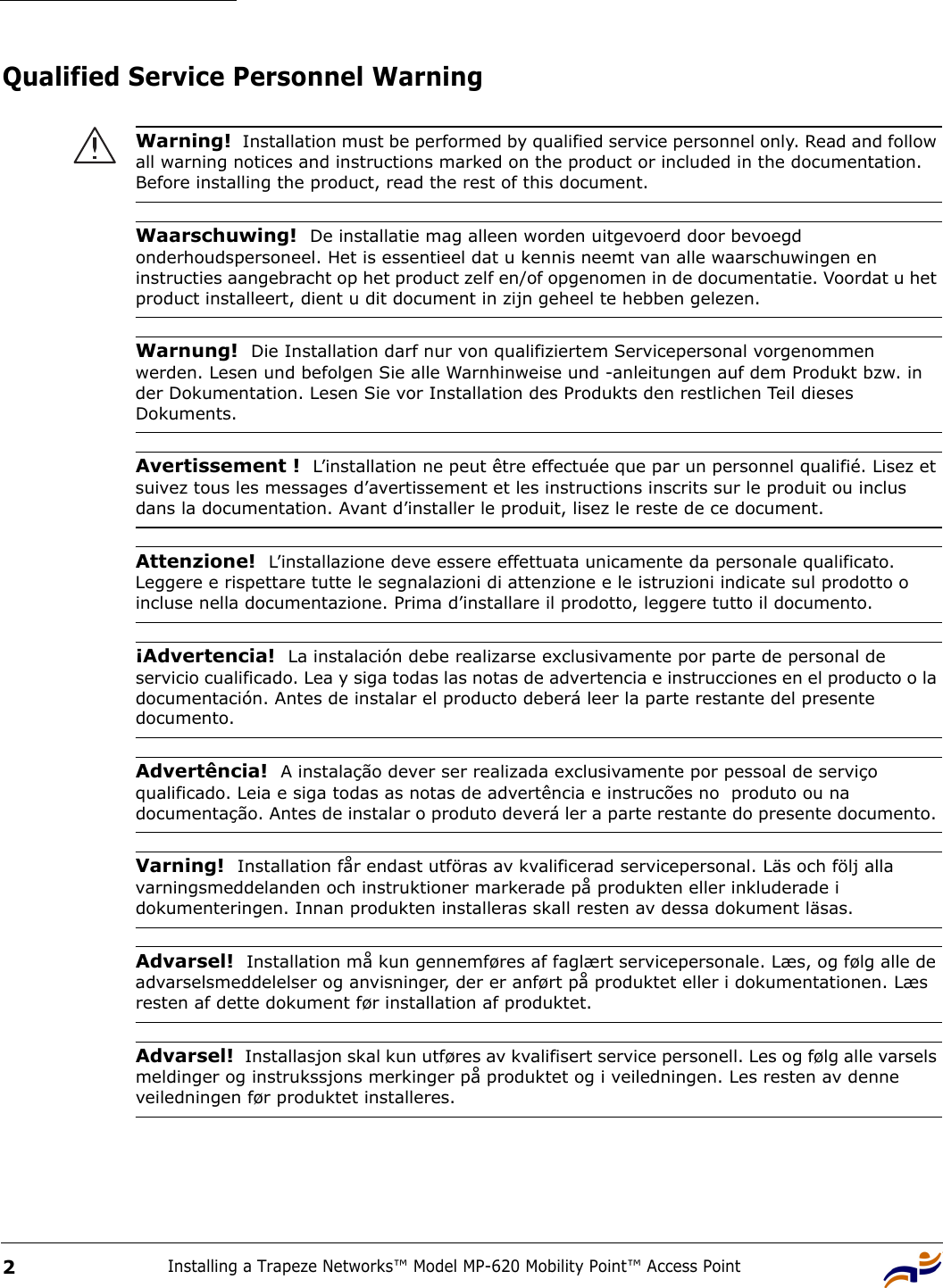
Installing a Trapeze Networks™ Model MP-620 Mobility Point™ Access Point2Qualified Service Personnel Warning Warning!  Installation must be performed by qualified service personnel only. Read and follow all warning notices and instructions marked on the product or included in the documentation. Before installing the product, read the rest of this document.Waarschuwing!  De installatie mag alleen worden uitgevoerd door bevoegd onderhoudspersoneel. Het is essentieel dat u kennis neemt van alle waarschuwingen en instructies aangebracht op het product zelf en/of opgenomen in de documentatie. Voordat u het product installeert, dient u dit document in zijn geheel te hebben gelezen.Warnung!  Die Installation darf nur von qualifiziertem Servicepersonal vorgenommen werden. Lesen und befolgen Sie alle Warnhinweise und -anleitungen auf dem Produkt bzw. in der Dokumentation. Lesen Sie vor Installation des Produkts den restlichen Teil dieses Dokuments. Avertissement !  L’installation ne peut être effectuée que par un personnel qualifié. Lisez et suivez tous les messages d’avertissement et les instructions inscrits sur le produit ou inclus dans la documentation. Avant d’installer le produit, lisez le reste de ce document.Attenzione!  L’installazione deve essere effettuata unicamente da personale qualificato. Leggere e rispettare tutte le segnalazioni di attenzione e le istruzioni indicate sul prodotto o incluse nella documentazione. Prima d’installare il prodotto, leggere tutto il documento.¡Advertencia!  La instalación debe realizarse exclusivamente por parte de personal de servicio cualificado. Lea y siga todas las notas de advertencia e instrucciones en el producto o la documentación. Antes de instalar el producto deberá leer la parte restante del presente documento. Advertência!  A instalação dever ser realizada exclusivamente por pessoal de serviço qualificado. Leia e siga todas as notas de advertência e instrucões no  produto ou na documentação. Antes de instalar o produto deverá ler a parte restante do presente documento. Varning!  Installation får endast utföras av kvalificerad servicepersonal. Läs och följ alla varningsmeddelanden och instruktioner markerade på produkten eller inkluderade i dokumenteringen. Innan produkten installeras skall resten av dessa dokument läsas.Advarsel!  Installation må kun gennemføres af faglært servicepersonale. Læs, og følg alle de advarselsmeddelelser og anvisninger, der er anført på produktet eller i dokumentationen. Læs resten af dette dokument før installation af produktet.Advarsel!  Installasjon skal kun utføres av kvalifisert service personell. Les og følg alle varsels meldinger og instrukssjons merkinger på produktet og i veiledningen. Les resten av denne veiledningen før produktet installeres.
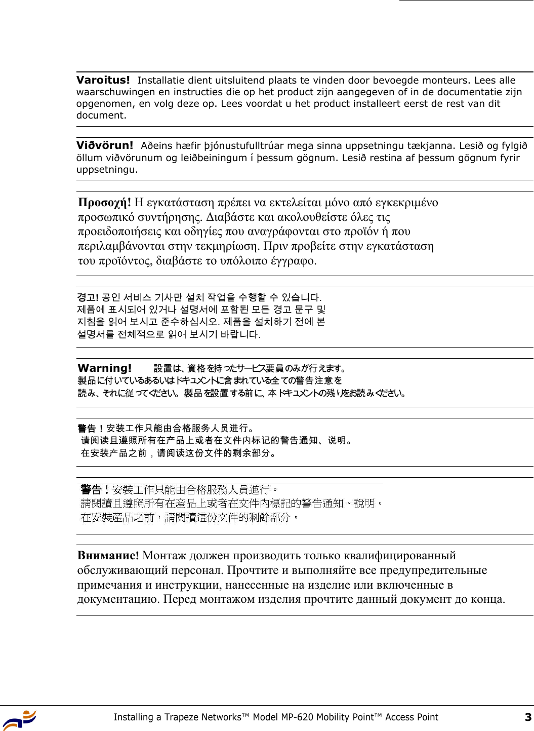
Installing a Trapeze Networks™ Model MP-620 Mobility Point™ Access Point3 Varoitus!  Installatie dient uitsluitend plaats te vinden door bevoegde monteurs. Lees alle waarschuwingen en instructies die op het product zijn aangegeven of in de documentatie zijn opgenomen, en volg deze op. Lees voordat u het product installeert eerst de rest van dit document.Viðvörun!  Aðeins hæfir þjónustufulltrúar mega sinna uppsetningu tækjanna. Lesið og fylgið öllum viðvörunum og leiðbeiningum í þessum gögnum. Lesið restina af þessum gögnum fyrir uppsetningu.Προσοχή! Η εγκατάσταση πρέπει να εκτελείται µόνο από εγκεκριµένο  προσωπικό συντήρησης. ∆ιαβάστε και ακολουθείστε όλες τις  προειδοποιήσεις και οδηγίες που αναγράφονται στο προϊόν ή που  περιλαµβάνονται στην τεκµηρίωση. Πριν προβείτε στην εγκατάσταση  του προϊόντος, διαβάστε το υπόλοιπο έγγραφο.  경고! 공인 서비스 기사만 설치 작업을 수행할 수 있습니다.  제품에 표시되어 있거나 설명서에 포함된 모든 경고 문구 및  지침을 읽어 보시고 준수하십시오. 제품을 설치하기 전에 본  설명서를 전체적으로 읽어 보시기 바랍니다. Warning!   設置は、資格を持ったサービス要員のみが行えます。  製品に付いているあるいはドキュメントに含まれている全ての警告注意を 読み、それに従ってください。 製品を設置する前に、本ドキュメントの残 りをお読 み ください。 警告!安装工作只能由合格服务人员进行。  请阅读且遵照所有在产品上或者在文件内标记的警告通知、说明。  在安装产品之前,请阅读这份文件的剩余部分。 Внимание! Монтаж должен производить только квалифицированный  обслуживающий персонал. Прочтите и выполняйте все предупредительные  примечания и инструкции, нанесенные на изделие или включенные в  документацию. Перед монтажом изделия прочтите данный документ до конца.
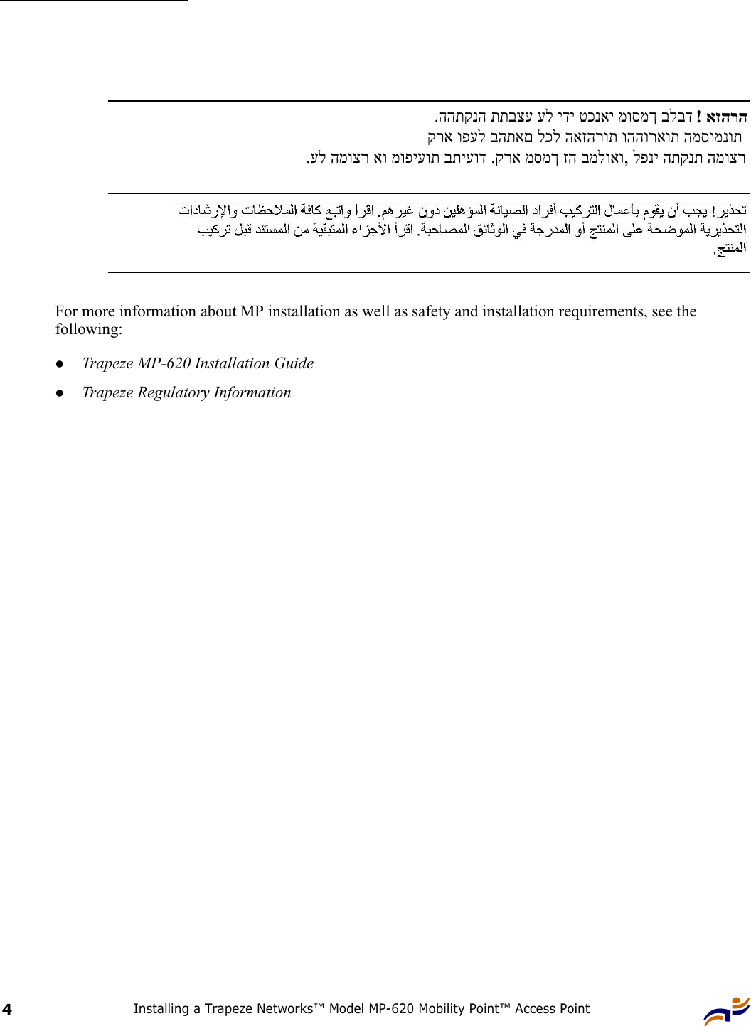
Installing a Trapeze Networks™ Model MP-620 Mobility Point™ Access Point4For more information about MP installation as well as safety and installation requirements, see the following:zTrapeze MP-620 Installation GuidezTrapeze Regulatory Information .ההתקנה תתבצע על ידי טכנאי מוסמך בלבד  ! אזהרהקרא ופעל בהתאם לכל האזהרות וההוראות המסומנות  .על המוצר או מופיעות בתיעוד .קרא מסמך זה במלואו, לפני התקנת המוצר
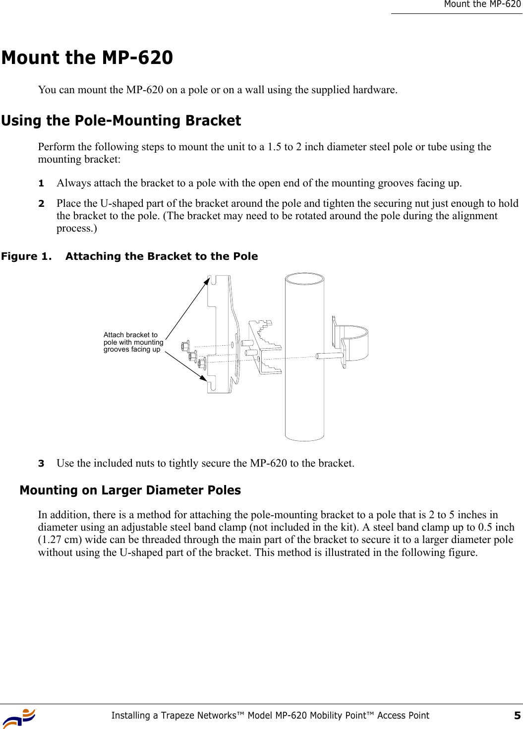
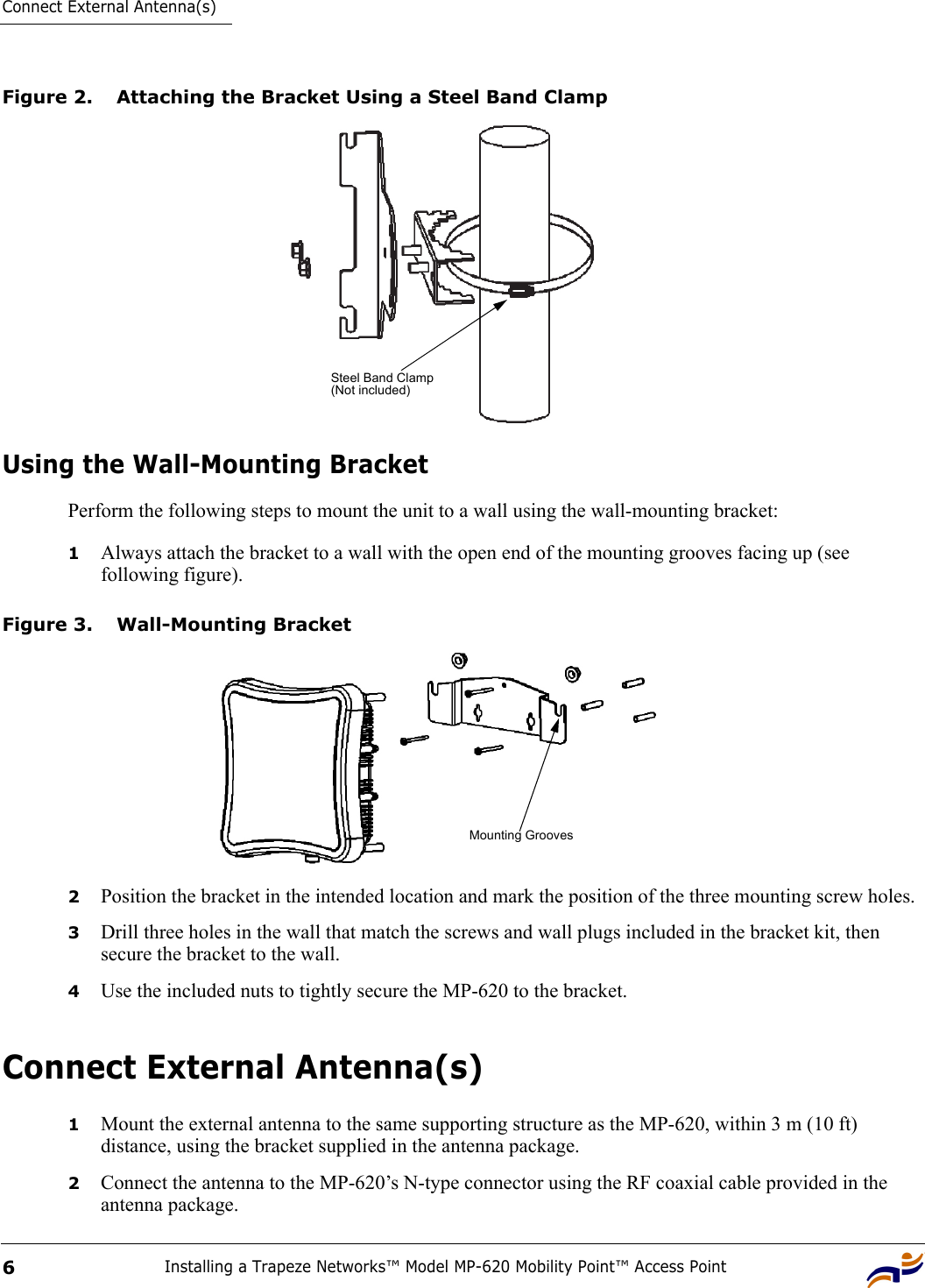
Installing a Trapeze Networks™ Model MP-620 Mobility Point™ Access Point5Mount the MP-620Mount the MP-620You can mount the MP-620 on a pole or on a wall using the supplied hardware.Using the Pole-Mounting BracketPerform the following steps to mount the unit to a 1.5 to 2 inch diameter steel pole or tube using the mounting bracket:1Always attach the bracket to a pole with the open end of the mounting grooves facing up.2Place the U-shaped part of the bracket around the pole and tighten the securing nut just enough to hold the bracket to the pole. (The bracket may need to be rotated around the pole during the alignment process.)Figure 1. Attaching the Bracket to the Pole3Use the included nuts to tightly secure the MP-620 to the bracket. Mounting on Larger Diameter PolesIn addition, there is a method for attaching the pole-mounting bracket to a pole that is 2 to 5 inches in diameter using an adjustable steel band clamp (not included in the kit). A steel band clamp up to 0.5 inch (1.27 cm) wide can be threaded through the main part of the bracket to secure it to a larger diameter pole without using the U-shaped part of the bracket. This method is illustrated in the following figure.Attach bracket to pole with mounting grooves facing up
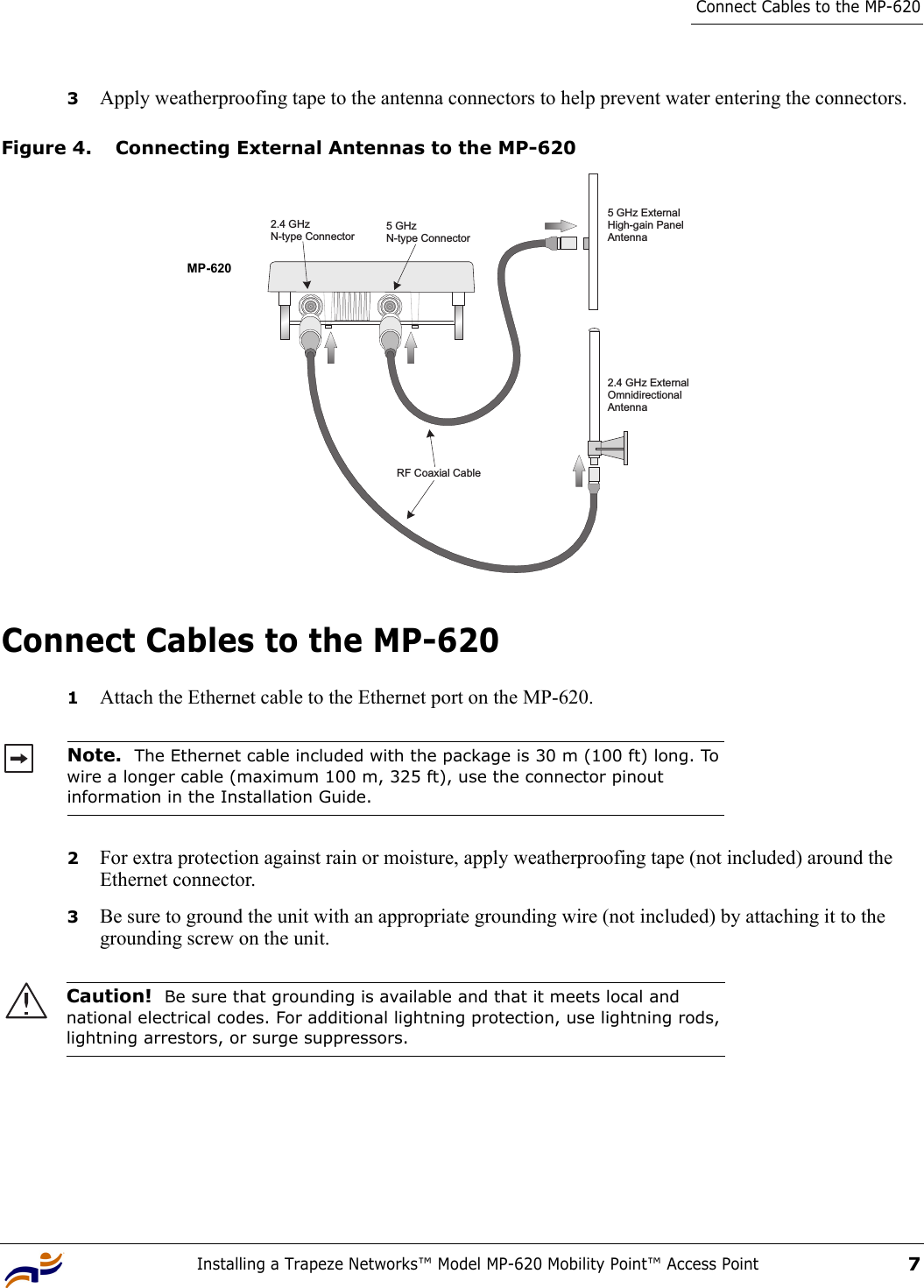
Connect External Antenna(s)Installing a Trapeze Networks™ Model MP-620 Mobility Point™ Access Point6Figure 2. Attaching the Bracket Using a Steel Band ClampUsing the Wall-Mounting BracketPerform the following steps to mount the unit to a wall using the wall-mounting bracket:1Always attach the bracket to a wall with the open end of the mounting grooves facing up (see following figure).Figure 3. Wall-Mounting Bracket2Position the bracket in the intended location and mark the position of the three mounting screw holes.3Drill three holes in the wall that match the screws and wall plugs included in the bracket kit, then secure the bracket to the wall.4Use the included nuts to tightly secure the MP-620 to the bracket. Connect External Antenna(s)1Mount the external antenna to the same supporting structure as the MP-620, within 3 m (10 ft) distance, using the bracket supplied in the antenna package.2Connect the antenna to the MP-620’s N-type connector using the RF coaxial cable provided in the antenna package.Steel Band Clamp(Not included)Mounting Grooves
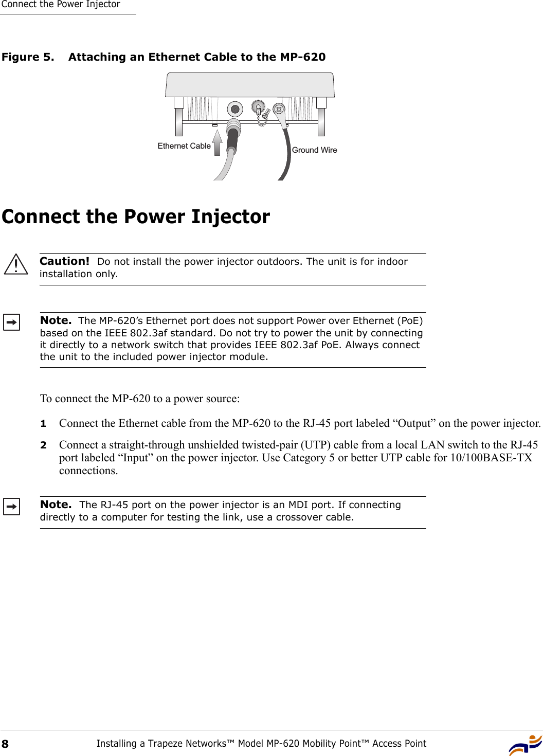
Installing a Trapeze Networks™ Model MP-620 Mobility Point™ Access Point7Connect Cables to the MP-6203Apply weatherproofing tape to the antenna connectors to help prevent water entering the connectors.Figure 4. Connecting External Antennas to the MP-620Connect Cables to the MP-6201Attach the Ethernet cable to the Ethernet port on the MP-620. 2For extra protection against rain or moisture, apply weatherproofing tape (not included) around the Ethernet connector.3Be sure to ground the unit with an appropriate grounding wire (not included) by attaching it to the grounding screw on the unit.Note.  The Ethernet cable included with the package is 30 m (100 ft) long. To wire a longer cable (maximum 100 m, 325 ft), use the connector pinout information in the Installation Guide.Caution!  Be sure that grounding is available and that it meets local and national electrical codes. For additional lightning protection, use lightning rods, lightning arrestors, or surge suppressors.RF Coaxial Cable2.4 GHz ExternalOmnidirectionalAntenna2.4 GHzN-type Connector5 GHzN-type Connector5 GHz ExternalHigh-gain PanelAntennaMP-620
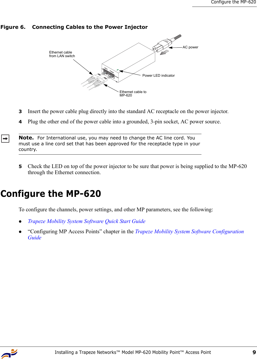
Connect the Power InjectorInstalling a Trapeze Networks™ Model MP-620 Mobility Point™ Access Point8Figure 5. Attaching an Ethernet Cable to the MP-620Connect the Power Injector To connect the MP-620 to a power source:1Connect the Ethernet cable from the MP-620 to the RJ-45 port labeled “Output” on the power injector.2Connect a straight-through unshielded twisted-pair (UTP) cable from a local LAN switch to the RJ-45 port labeled “Input” on the power injector. Use Category 5 or better UTP cable for 10/100BASE-TX connections.Caution!  Do not install the power injector outdoors. The unit is for indoor installation only.Note.  The MP-620’s Ethernet port does not support Power over Ethernet (PoE) based on the IEEE 802.3af standard. Do not try to power the unit by connecting it directly to a network switch that provides IEEE 802.3af PoE. Always connect the unit to the included power injector module.Note.  The RJ-45 port on the power injector is an MDI port. If connecting directly to a computer for testing the link, use a crossover cable.Ground WireEthernet Cable
Installing a Trapeze Networks™ Model MP-620 Mobility Point™ Access Point9Configure the MP-620Figure 6. Connecting Cables to the Power Injector3Insert the power cable plug directly into the standard AC receptacle on the power injector.4Plug the other end of the power cable into a grounded, 3-pin socket, AC power source.5Check the LED on top of the power injector to be sure that power is being supplied to the MP-620 through the Ethernet connection.Configure the MP-620To configure the channels, power settings, and other MP parameters, see the following:zTrapeze Mobility System Software Quick Start Guidez“Configuring MP Access Points” chapter in the Trapeze Mobility System Software Configuration GuideNote.  For International use, you may need to change the AC line cord. You must use a line cord set that has been approved for the receptacle type in your country.Input OutputEthernet cable from LAN switchEthernet cable to MP-620AC powerPower LED indicator
Configure the MP-620Installing a Trapeze Networks™ Model MP-620 Mobility Point™ Access Point10

Navigation menu