Japan Radio NTG420 Solid State Transmitter-Receiver User Manual SSradarMaintenanceManual
Japan Radio Co Ltd. Solid State Transmitter-Receiver SSradarMaintenanceManual
Contents
- 1. Usera manual(Installation)
- 2. Users manual(Operation)
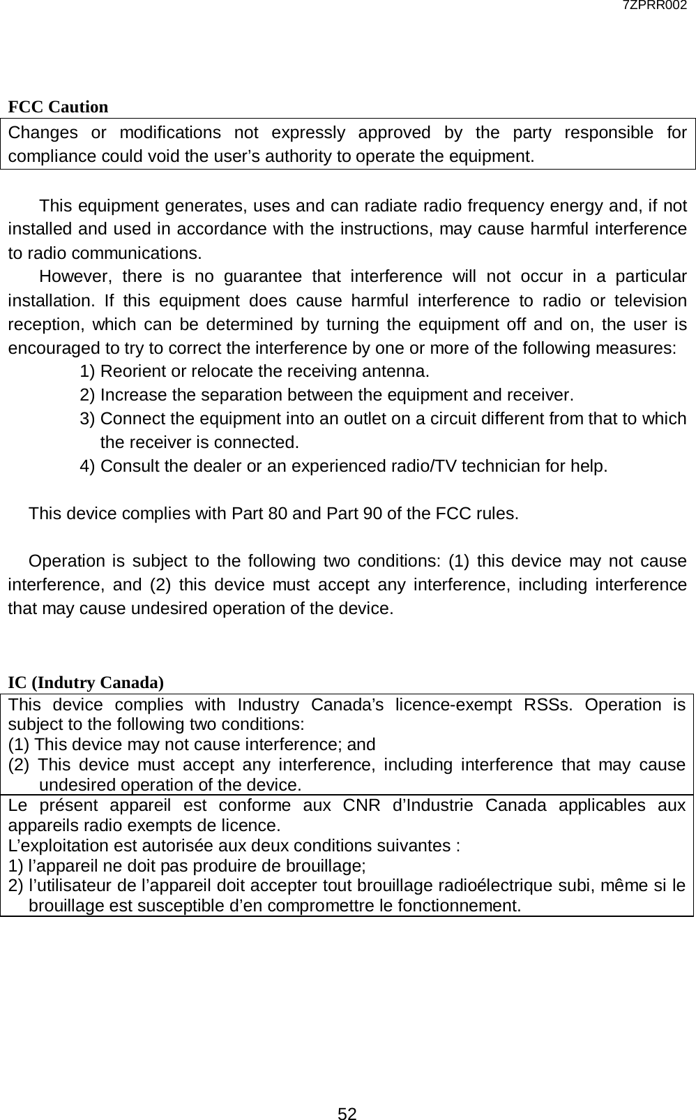
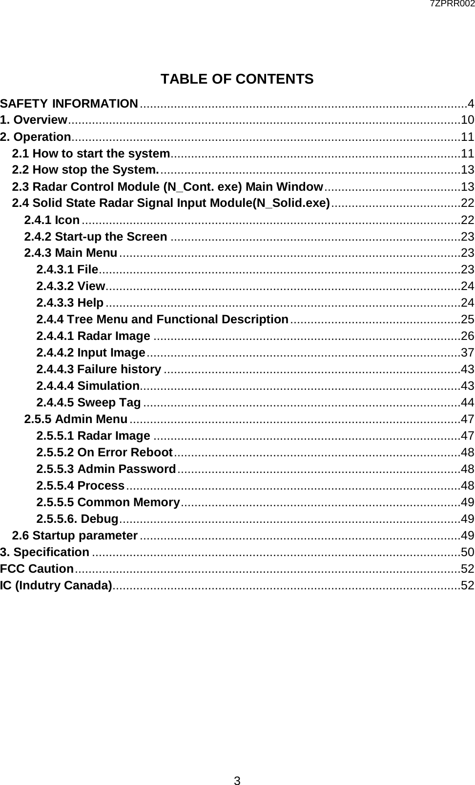
Users manual(Operation)

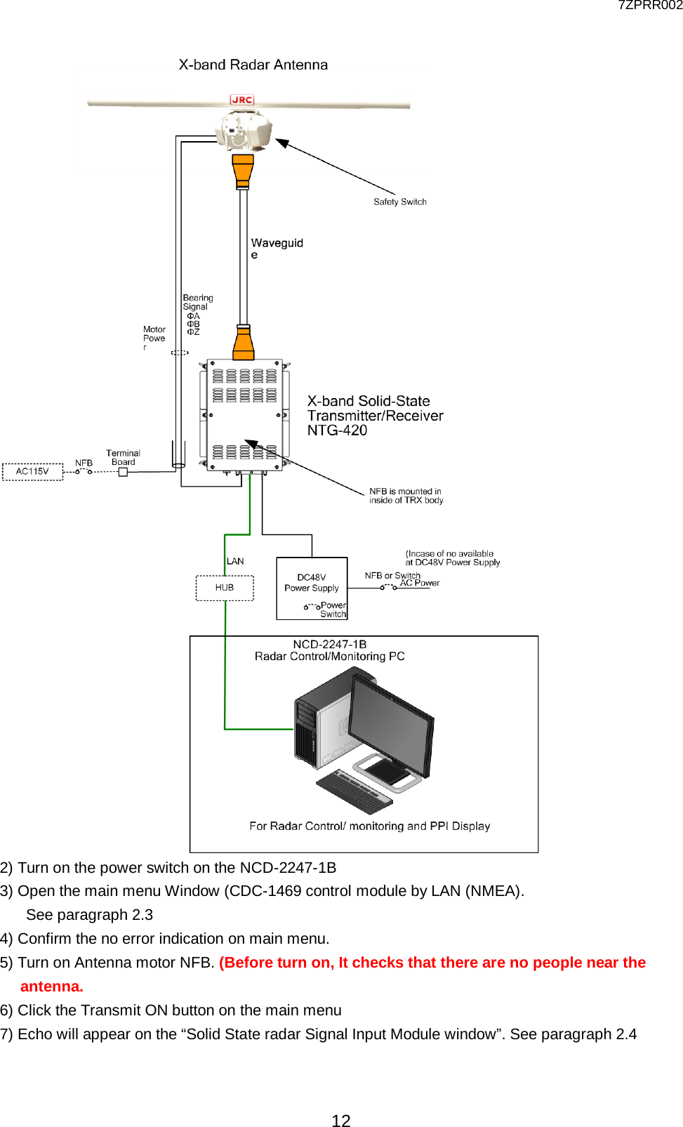
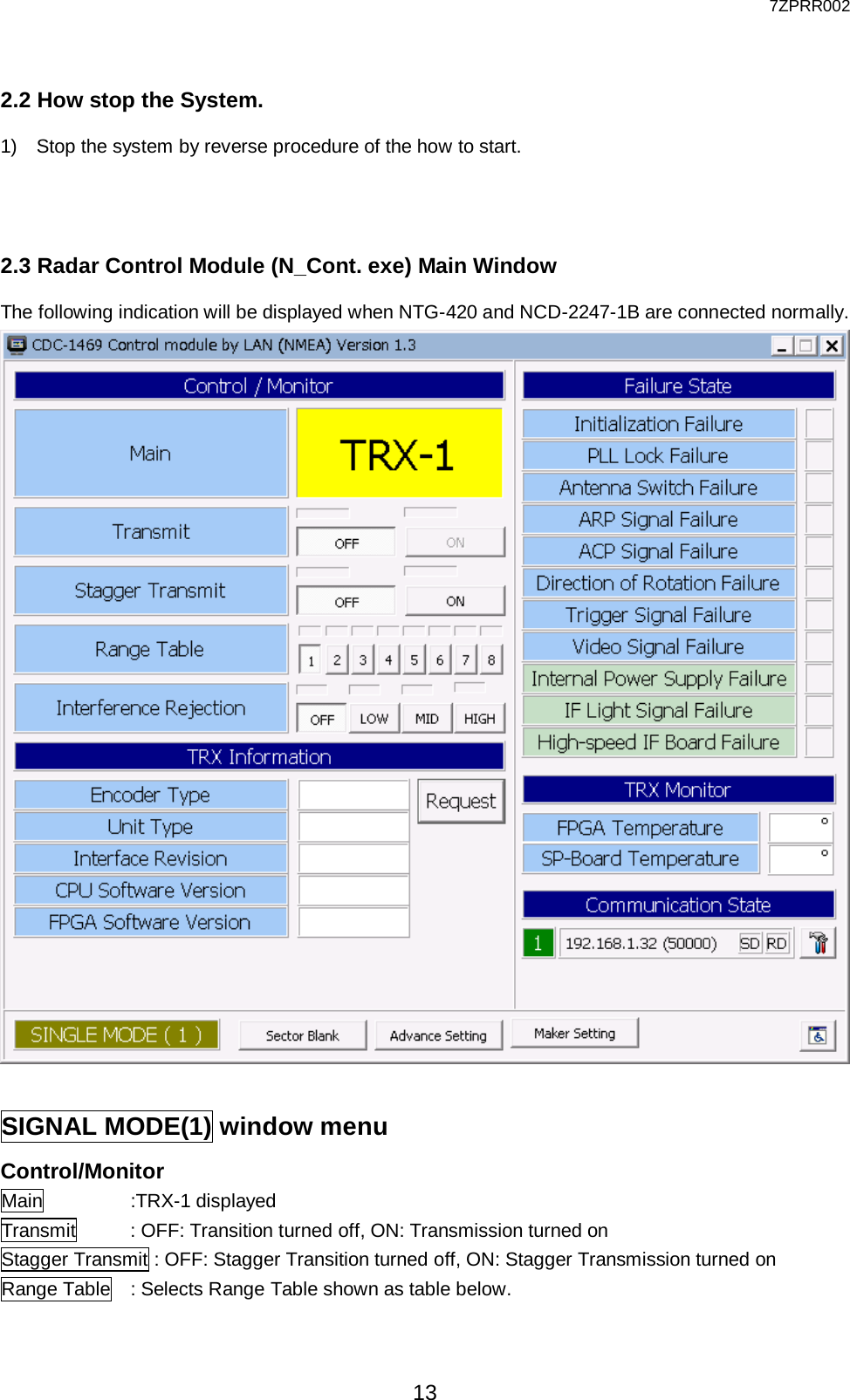
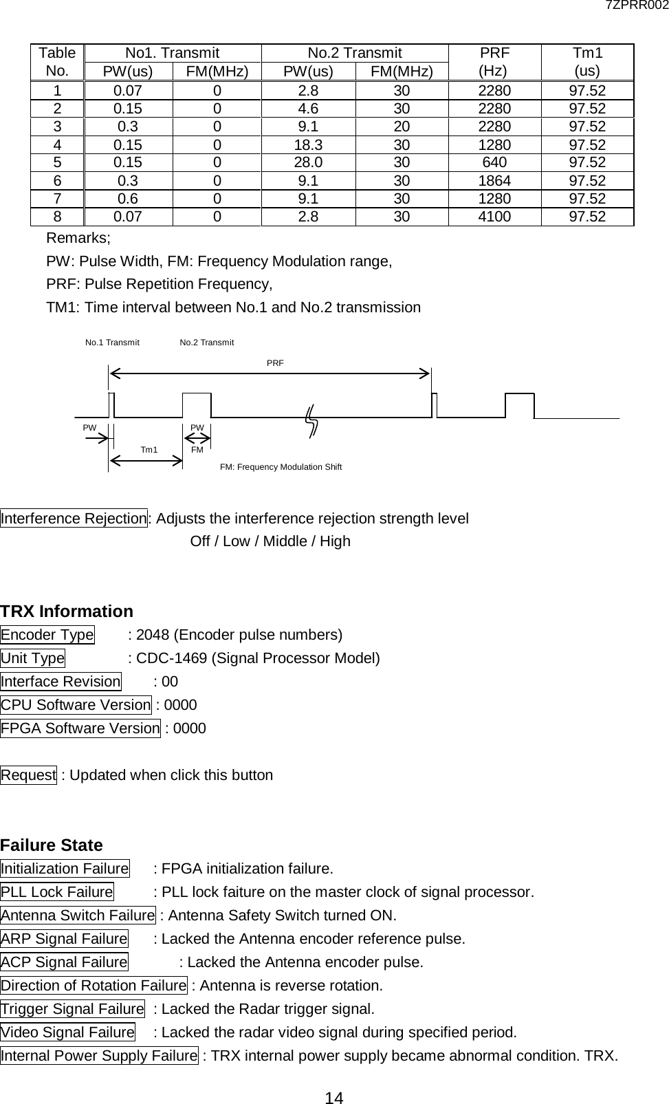
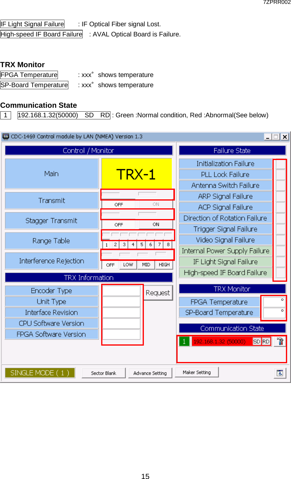
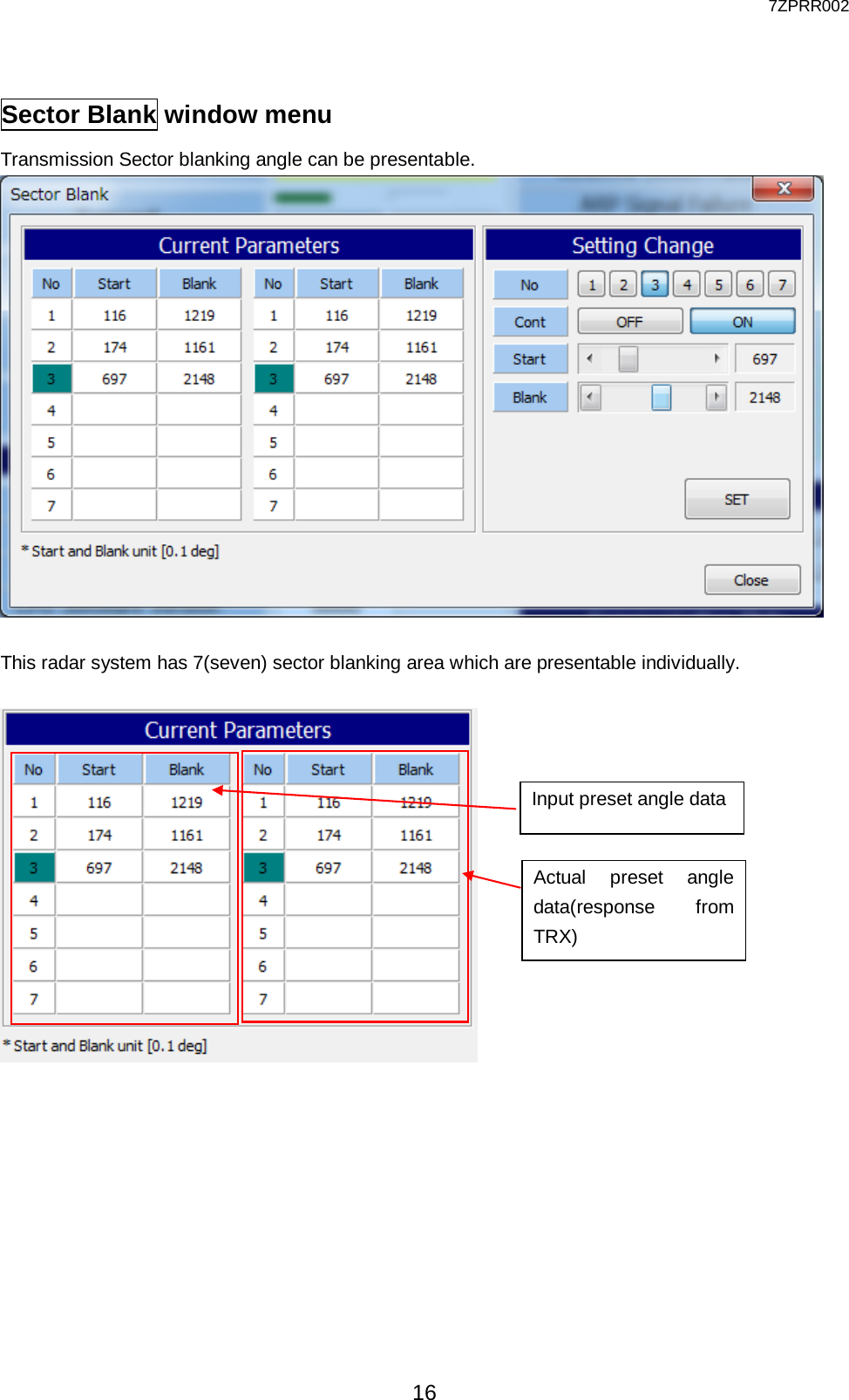
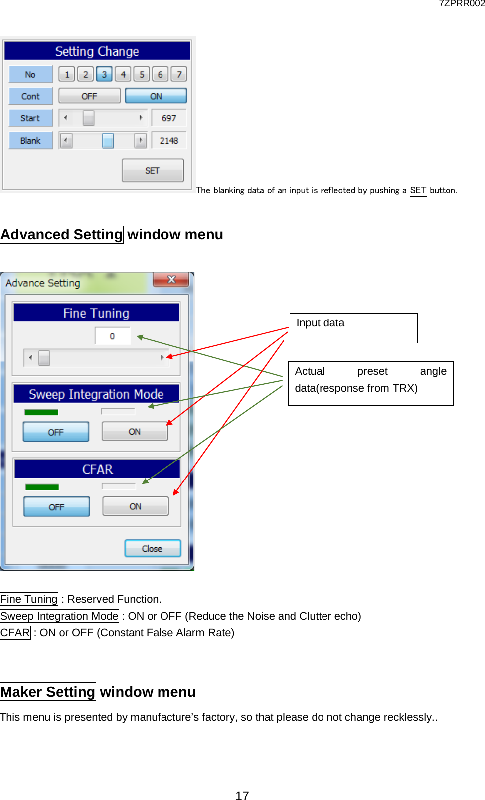
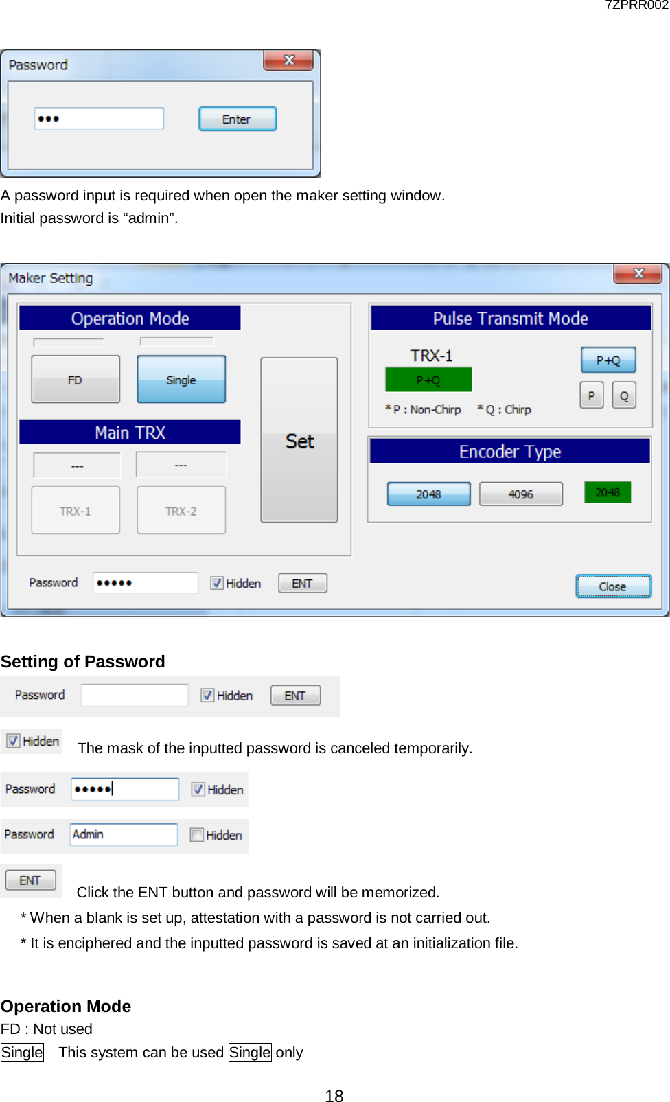
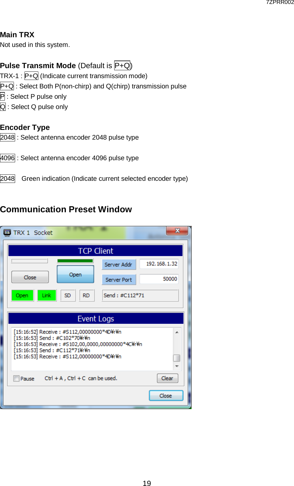
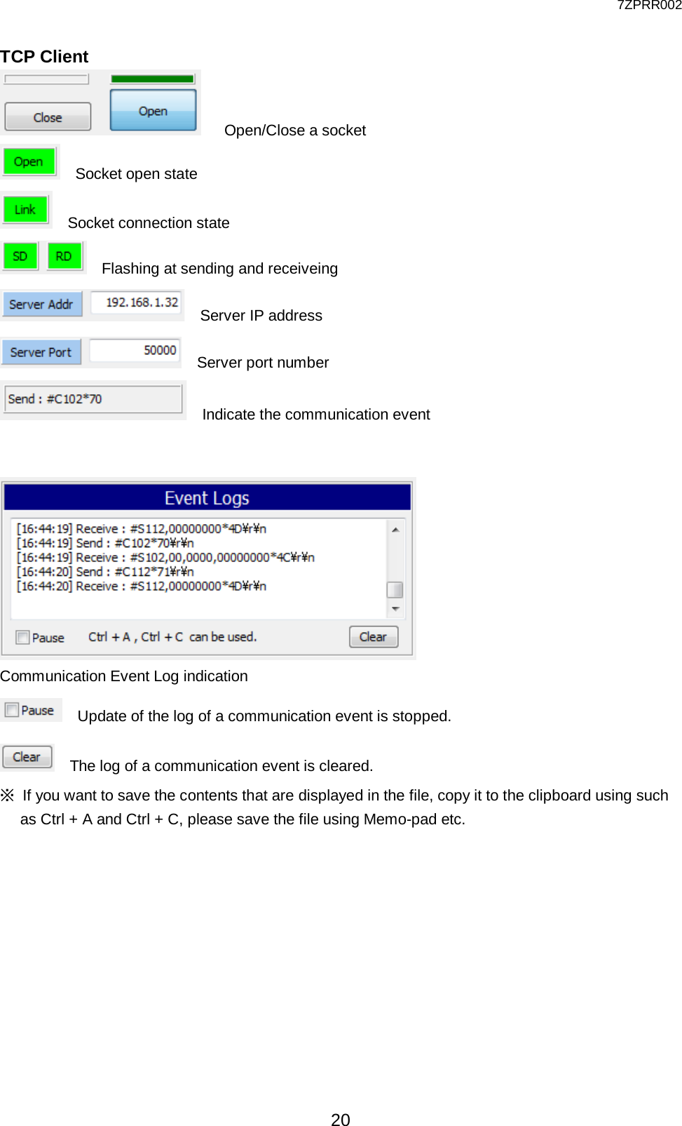
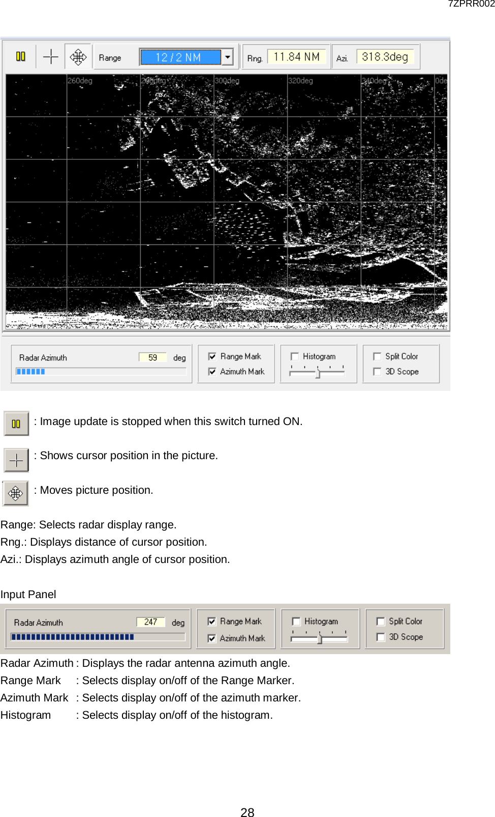
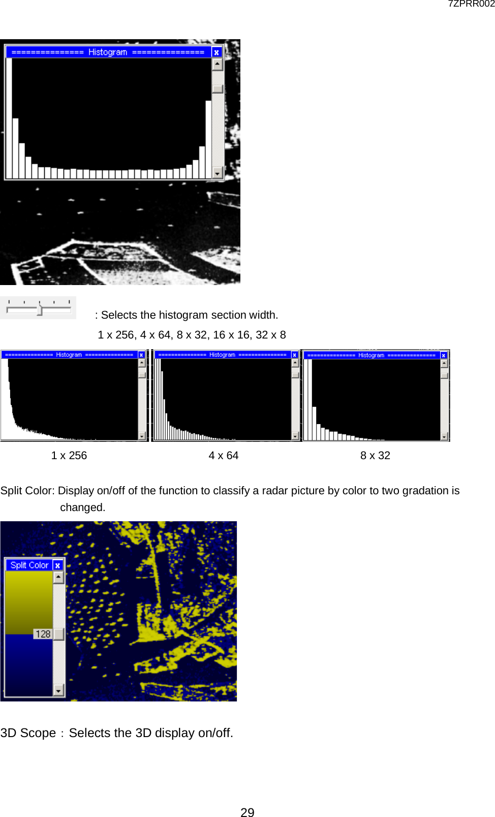
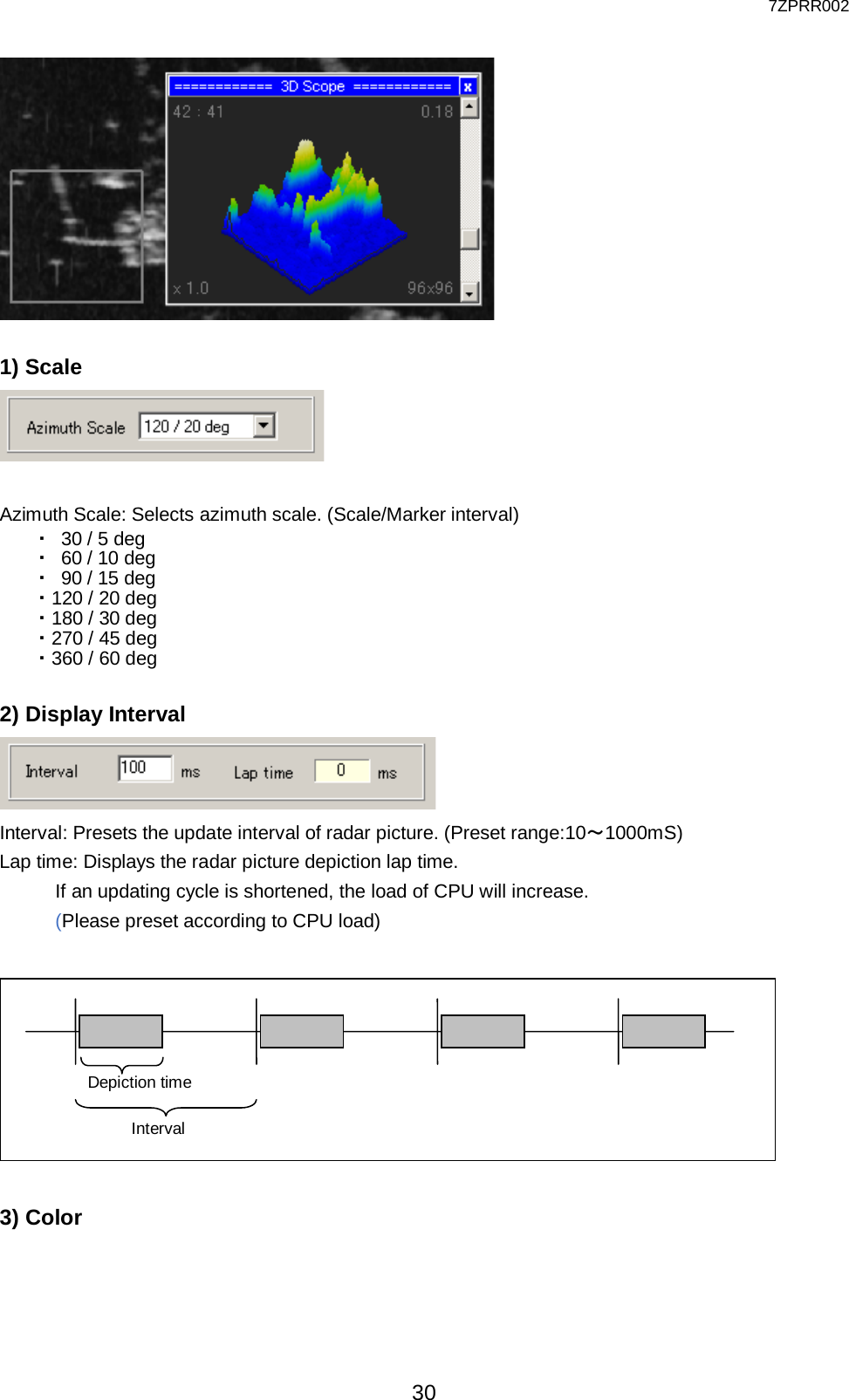
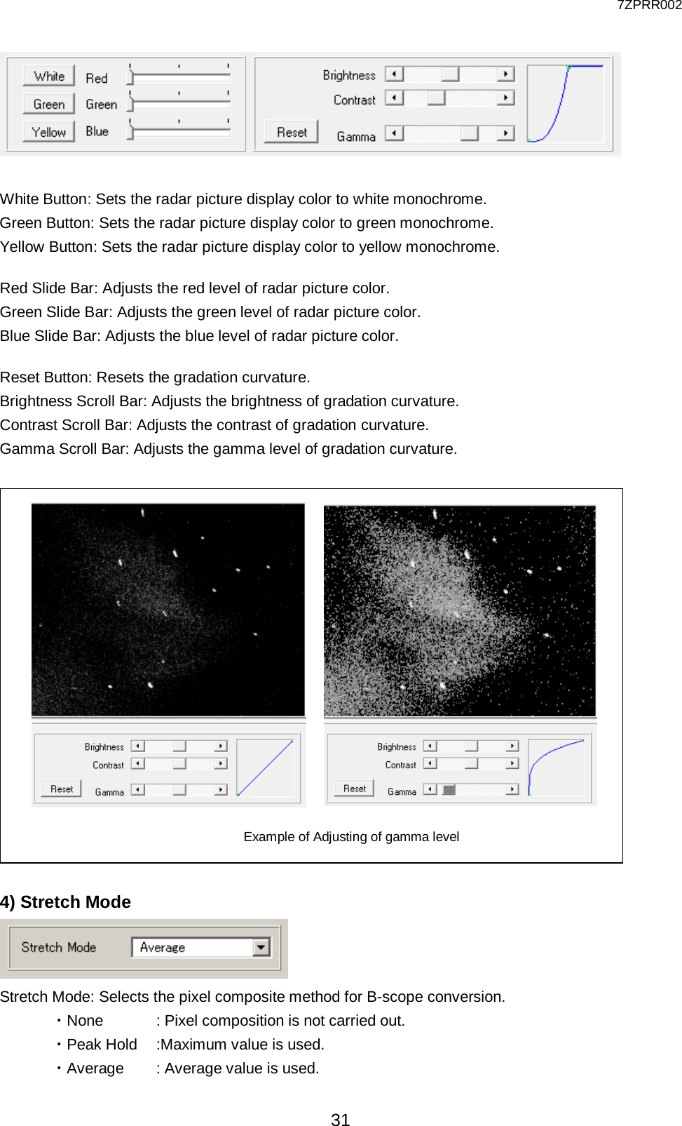
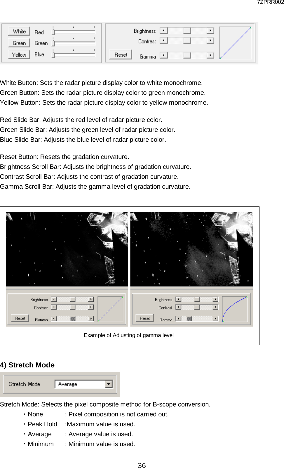
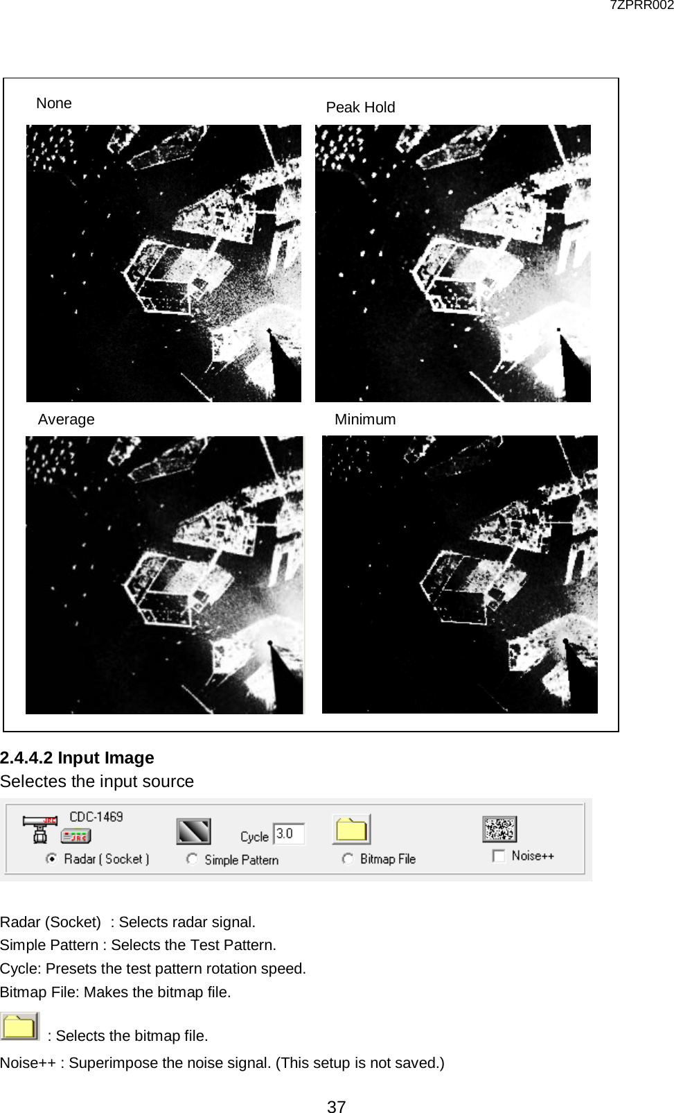
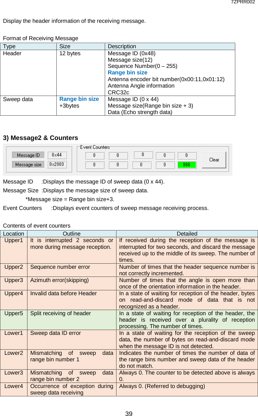
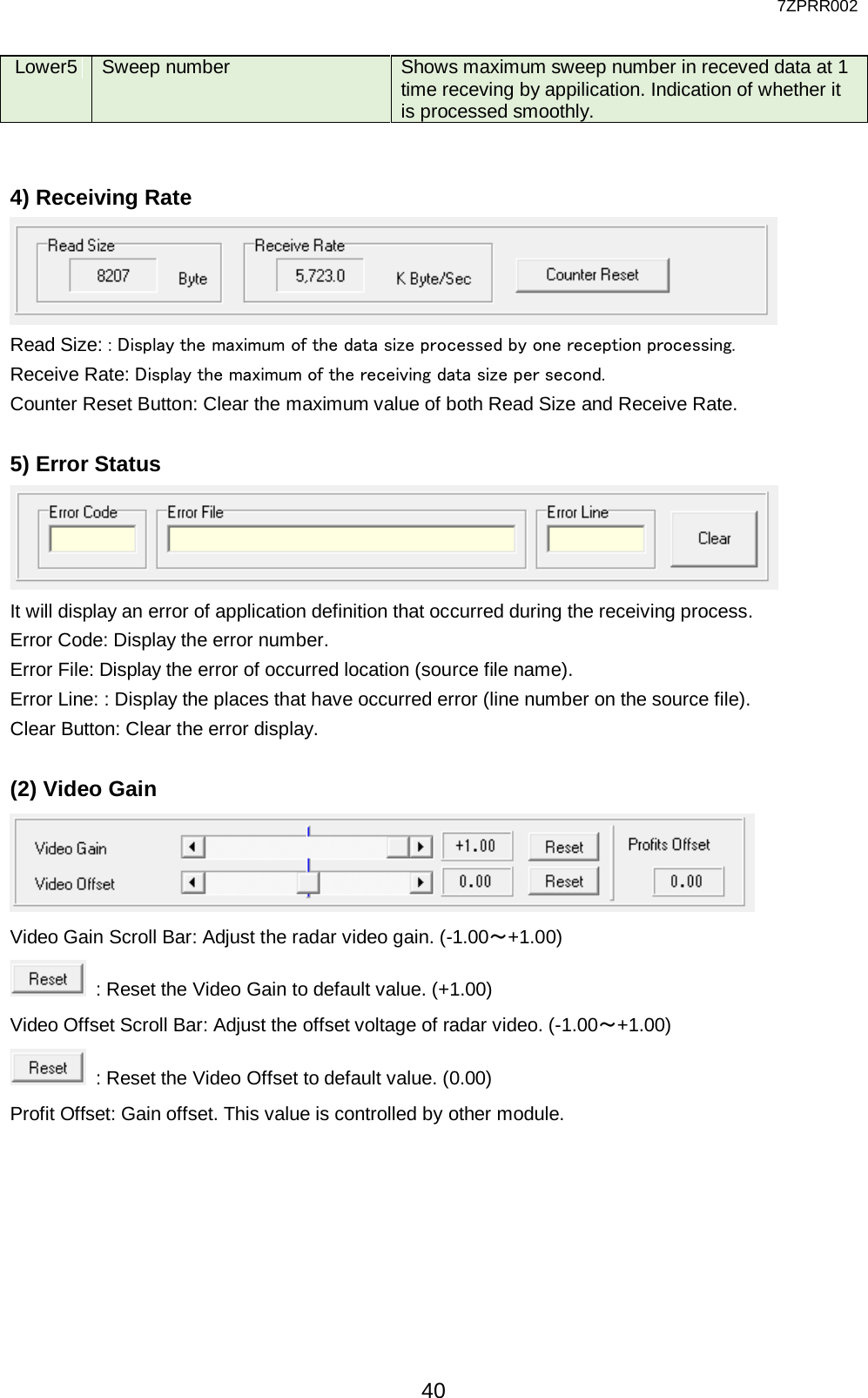
![7ZPRR002 38 (1) Socket The TCP/IP UDP client socket for connecting with radar signal processing equipment (CDC-1469) on NTG-420 SSTRX is set up. Startup – Auto Open: Automatically sets the socket to the application startup in the case to be open. Port No: Presets the receiving port number of UDP socket. Status : Status of UDP socket. : Close : Open : Ready for Transmission : Under transmission : Waiting the receiving : Under receiving Open(or Close) Button : Open (or close) the socket Receive Buff Size : Presets the receiving buffer size. (1 - 512MB) 1) Radar Information Azimuth : Displays radar antenna azimuth angle. (Latest sweep message angle) ACP Resolution : Displays ACP resolution. Rotational Period : Displays Antenna revolution period and rotation speed(rpm). Azimuth Resolution]: Displays azimuth resolution. (The value which divided 360 degrees by the number of sweeps) 2) Message1](https://usermanual.wiki/Japan-Radio/NTG420.Users-manual-Operation/User-Guide-3102730-Page-38.png)
![7ZPRR002 45 None(0): No hardware Tag. Range bin Description Remarks 4080~4095 Padding data 16bytes 0 Fixed 3~4079 Radar picture data 3 - 4079 Valid 2 Radar picture data 2 Valid 1 Radar picture data 1 Valid 0 Radar picture data 0 Valid PciVdo(16): Pci – Vdi format Range bin Description Remarks 16~4095 Radar picture data 0 - 4079 Valid 15 Command register H 0 Fixed 14 Command register L 0 Fixed 13 End distance H Valid 12 End distance L Valid 11 Start distance H 0 Fixed 10 Start distance L 0 Fixed 9 Times of day H 0 Fixed 8 Times of day L 0 Fixed 7 Dummy uncertainty 6 PPS counter value H 0 Fixed 5 PPS counter value M 0 Fixed 4 PPS canter value L 0 Fixed 3 External Tag H 0 Fixed 2 External Tag L 0 Fixed 1 Radar antenna azimuth H [65536 / 360] Valid 0 Radar antenna azimuth L [65536 / 360] Valid PciRvi(4) : Pci – Rvi format Range bin Description Remarks 4084~4095 Padding data 12 bytes 0 Fixed 4~4083 Radar picture data 0 - 4079 Valid 3 External Tag H 0 Fixed 2 External Tag L 0 Fixed 1 Radar antenna azimuth H [65536 / 360] Valid 0 Radar antenna azimuth L [65536 / 360] Valid](https://usermanual.wiki/Japan-Radio/NTG420.Users-manual-Operation/User-Guide-3102730-Page-45.png)
![7ZPRR002 46 PciRvi(16): Pci – Rvi format + 12 bytes padding Range bin Description Remarks 16~4095 Radar picture data 0 - 4079 Valid 4~15 Padding data 12bytes 0 Fixed 3 External Tag H 0 Fixed 2 External Tag L 0 Fixed 1 Radar antenna azimuth H [65536 / 360] Valid 0 Radar antenna azimuth L [65536 / 360] Valid Nams(10): Nams format Range bin Description Remarks 4090~4095 Padding data 6bytes (=0) 0 Fixed 10~4089 Radar picture data 0 - 4079 Valid 9 End distance H Valid 8 End distance L Valid 7 Start distance H 0 Fixed 6 Start distance L 0 Fixed 5 Radar antenna azimuth H [65536 / 360] Valid 4 Radar antenna azimuth L [65536 / 360] Valid 3 PPS times of day H 0 Fixed 2 PPS times of day MH 0 Fixed 1 PPS times of day ML 0 Fixed 0 PPS times of day L 0 Fixed Nams(16): Nams format + 6bytes padding Range bin Description Remarks 16~4095 Radar picture data 0 - 4079 Valid 10~15 Padding data 6bytes 0 Fixed 9 End distance H Valid 8 End distance L Valid 7 Start distance H 0 Fixed 6 Start distance L 0 Fixed 5 Radar antenna azimuth H [65536 / 360] Valid 4 Radar antenna azimuth L [65536 / 360] Valid 3 PPS times of day H 0 Fixed 2 PPS times of day MH 0 Fixed 1 PPS times of day ML 0 Fixed 0 PPS times of day L 0 Fixed](https://usermanual.wiki/Japan-Radio/NTG420.Users-manual-Operation/User-Guide-3102730-Page-46.png)