Japan Radio NTG420 Solid State Transmitter-Receiver User Manual Usera manual Installation
Japan Radio Co Ltd. Solid State Transmitter-Receiver Usera manual Installation
Contents
- 1. Usera manual(Installation)
- 2. Users manual(Operation)
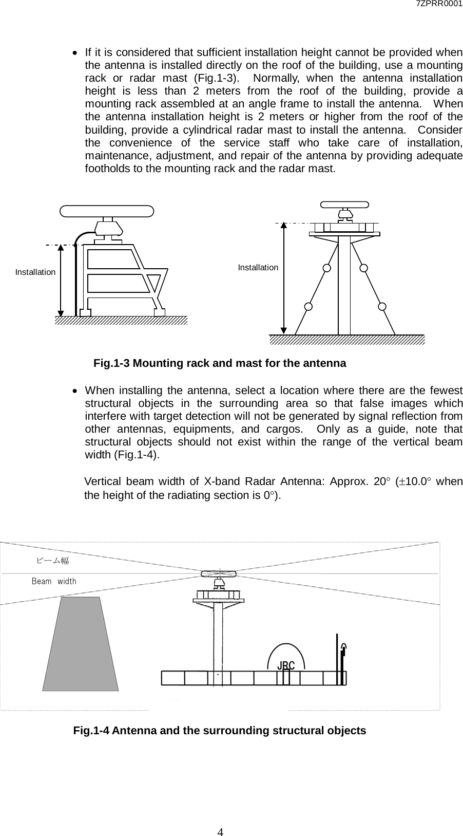
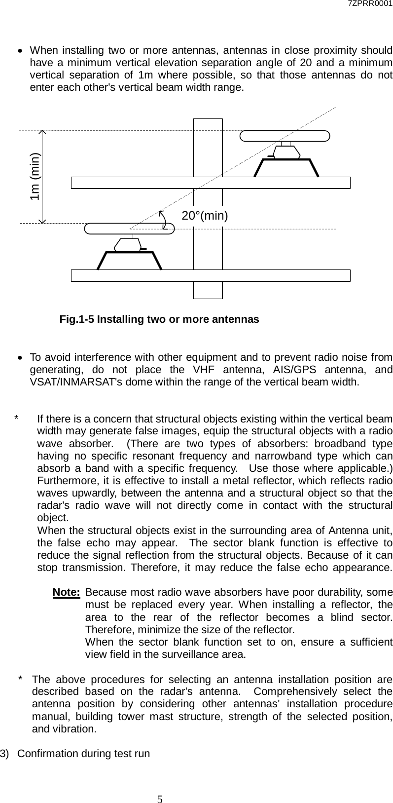
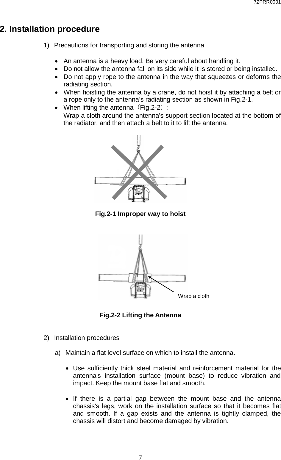
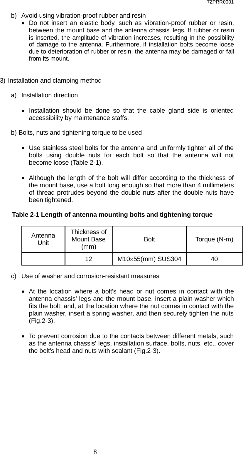
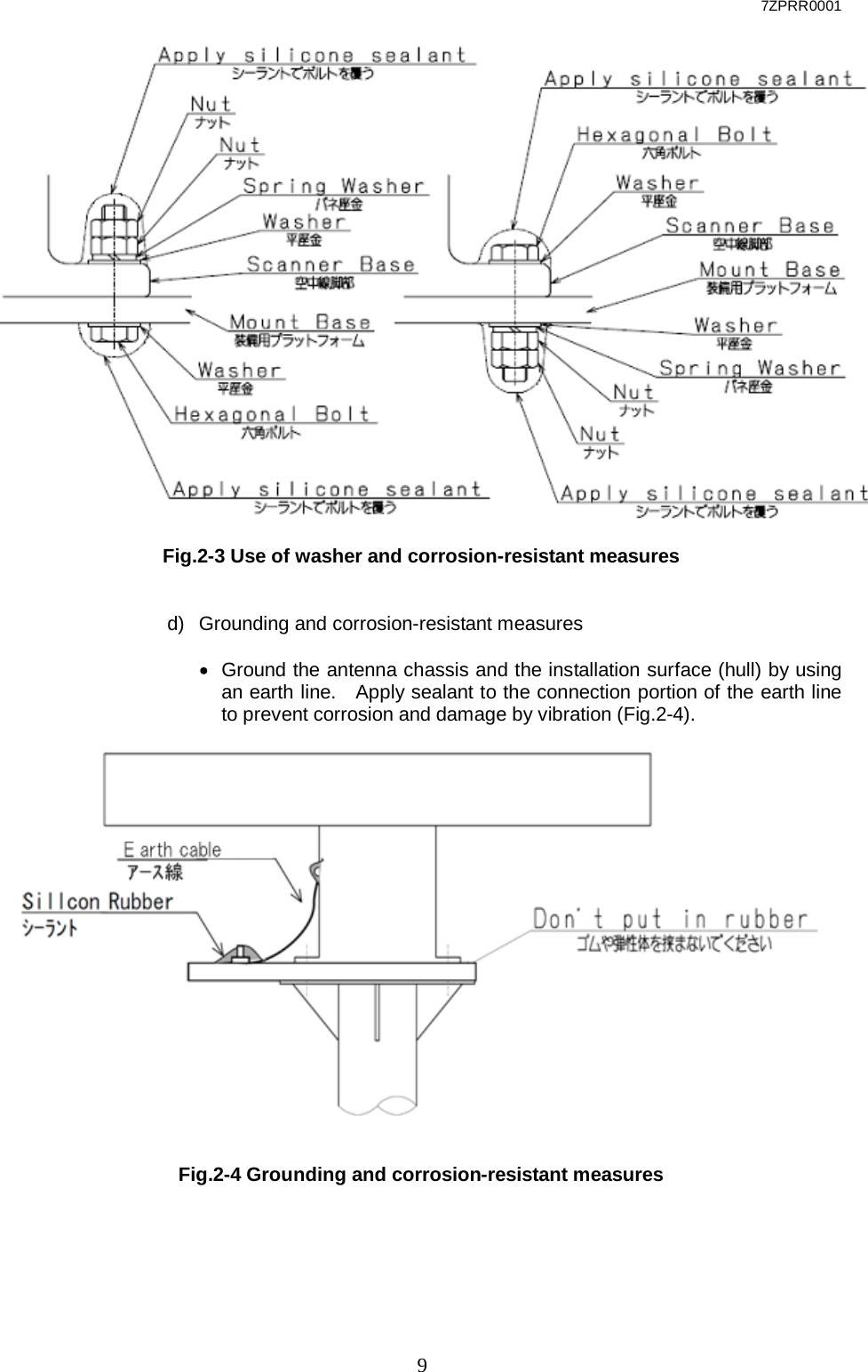
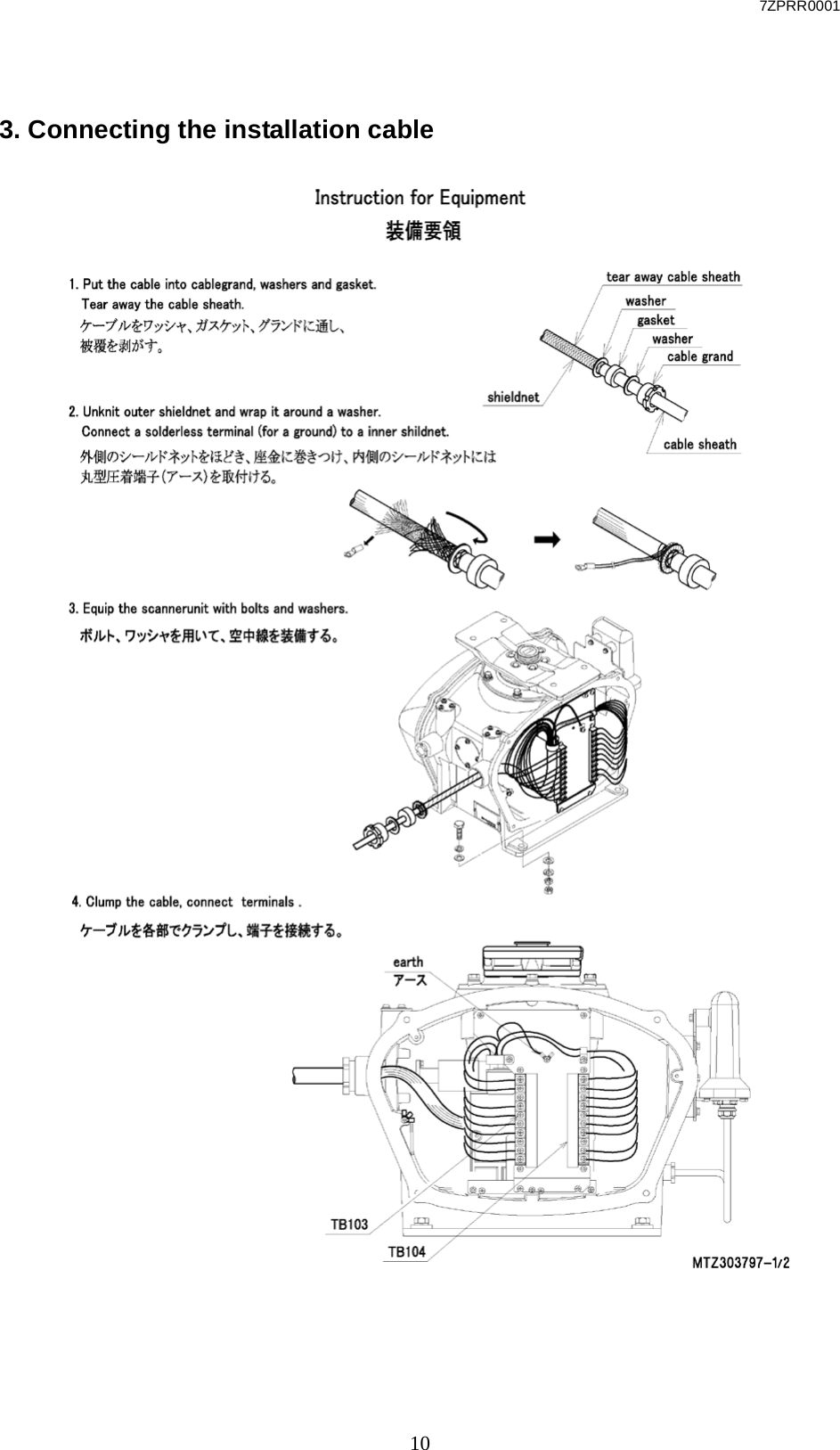
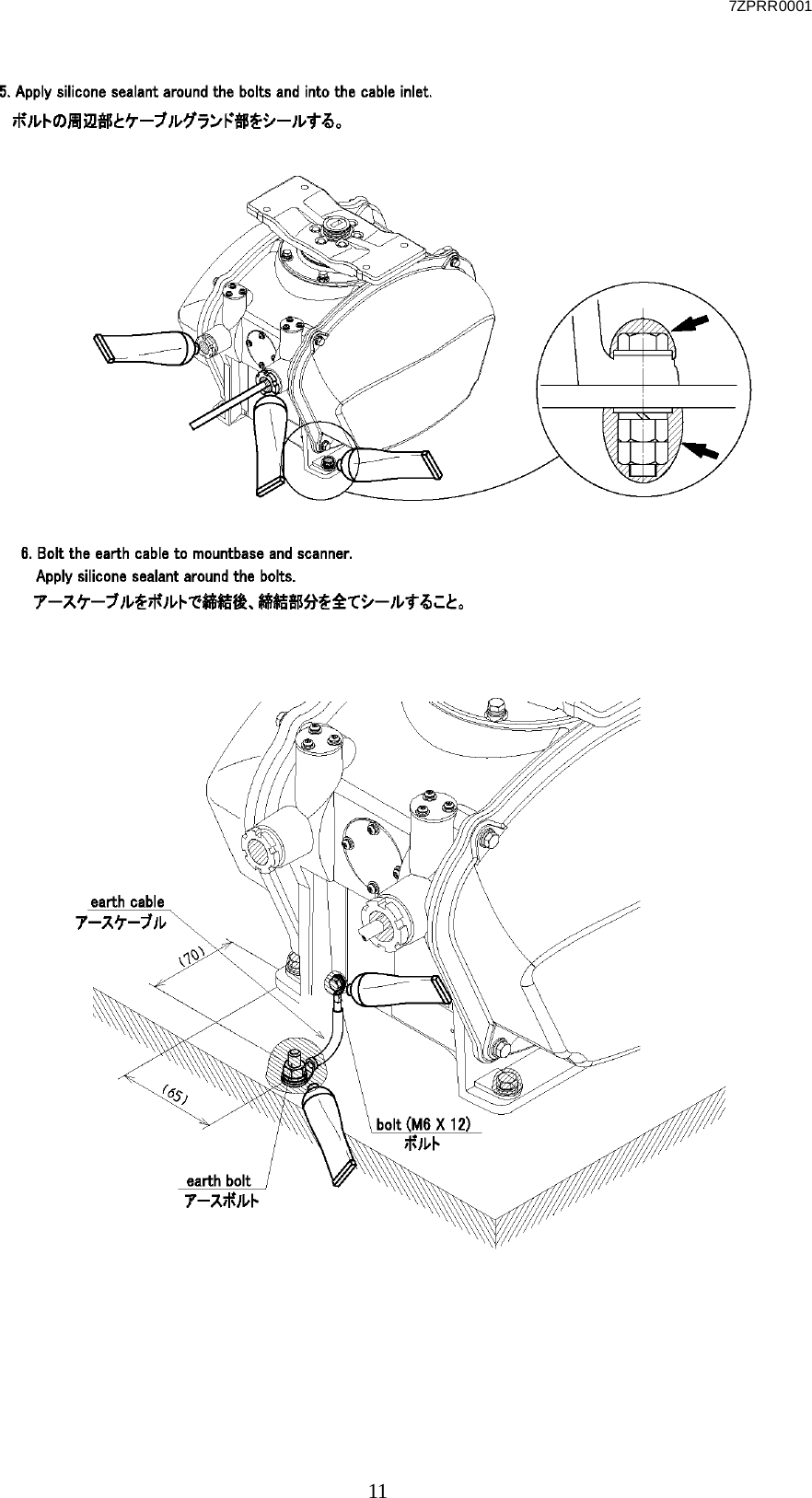
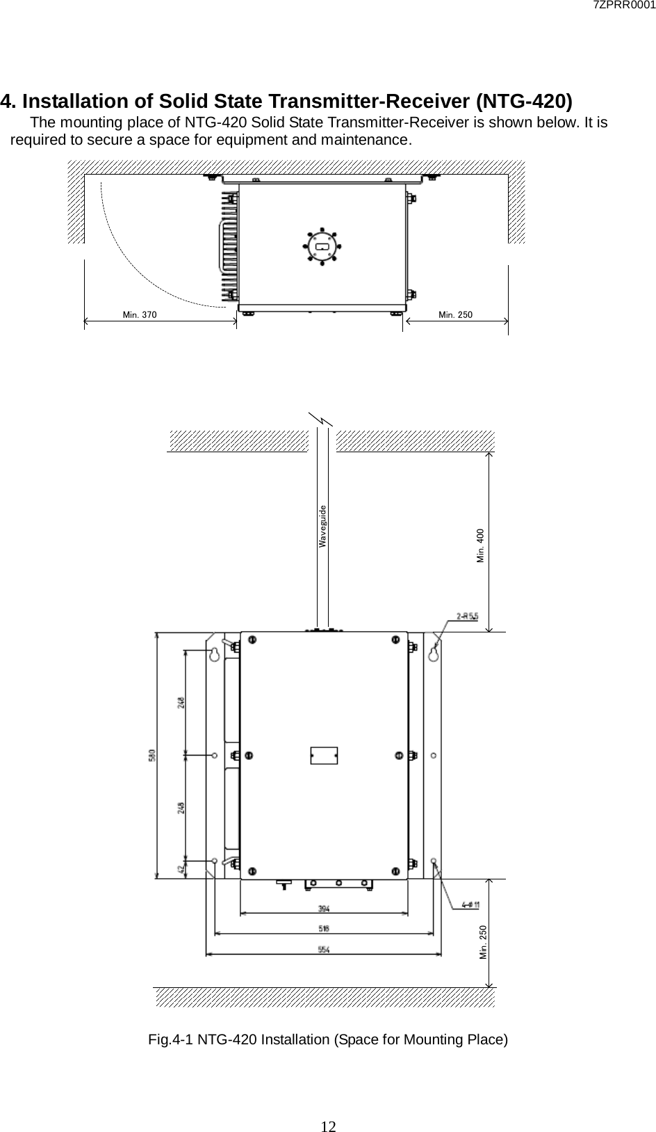
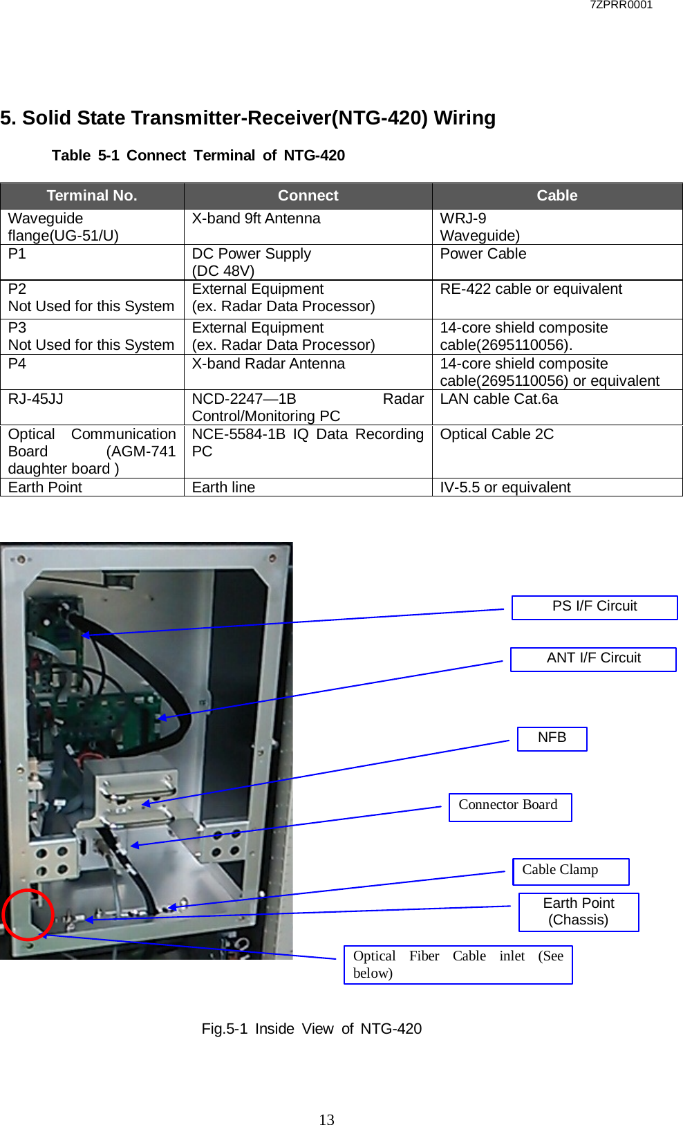
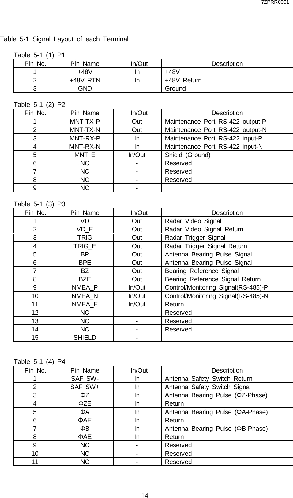
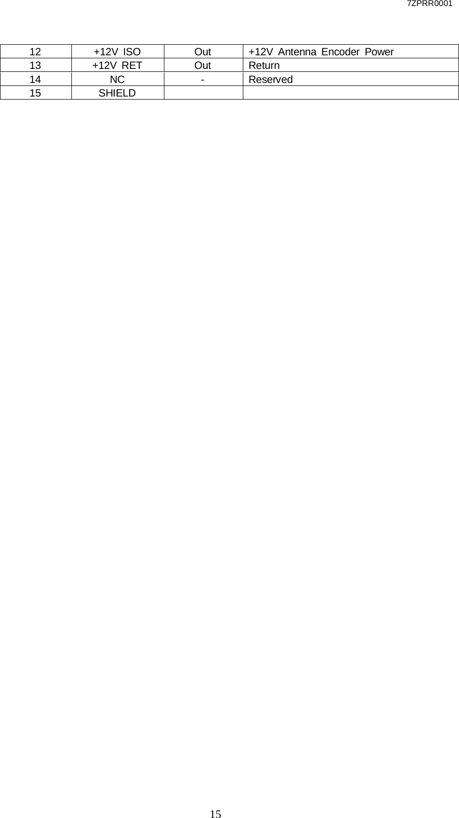
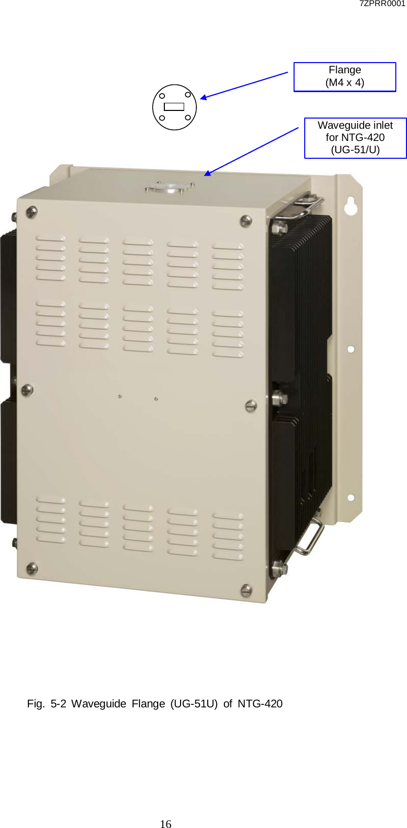
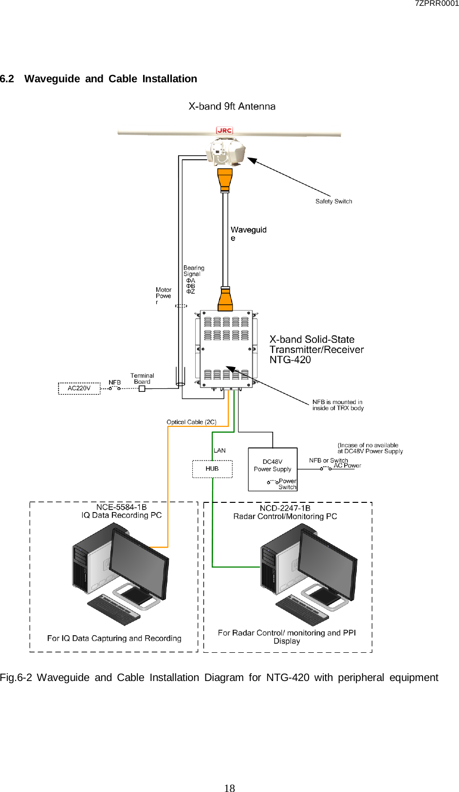
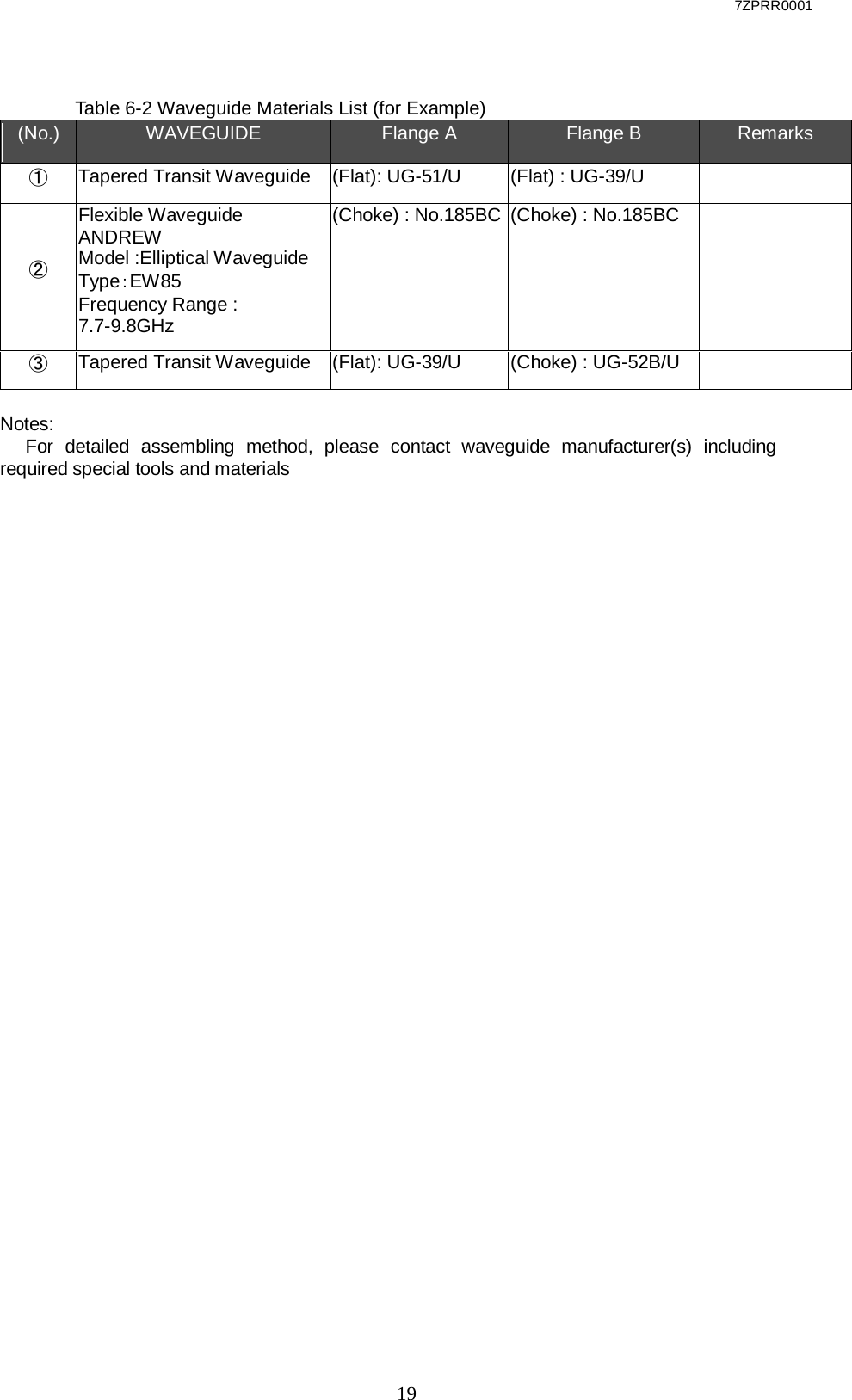
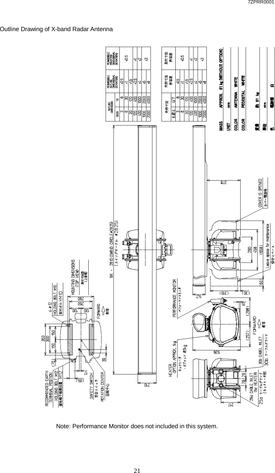
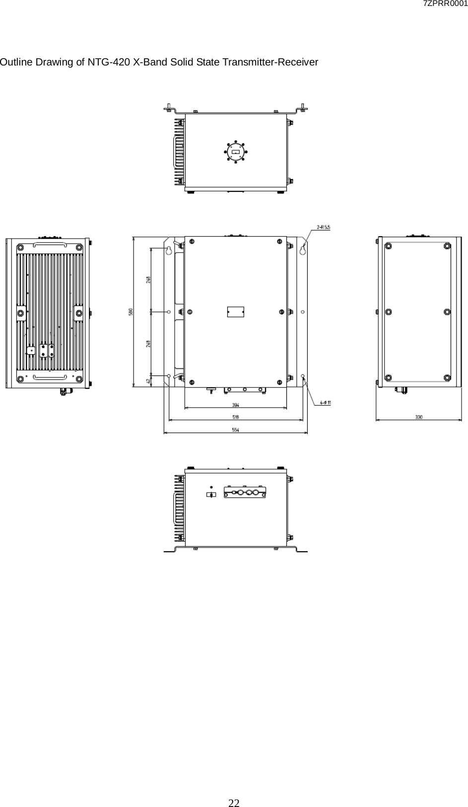
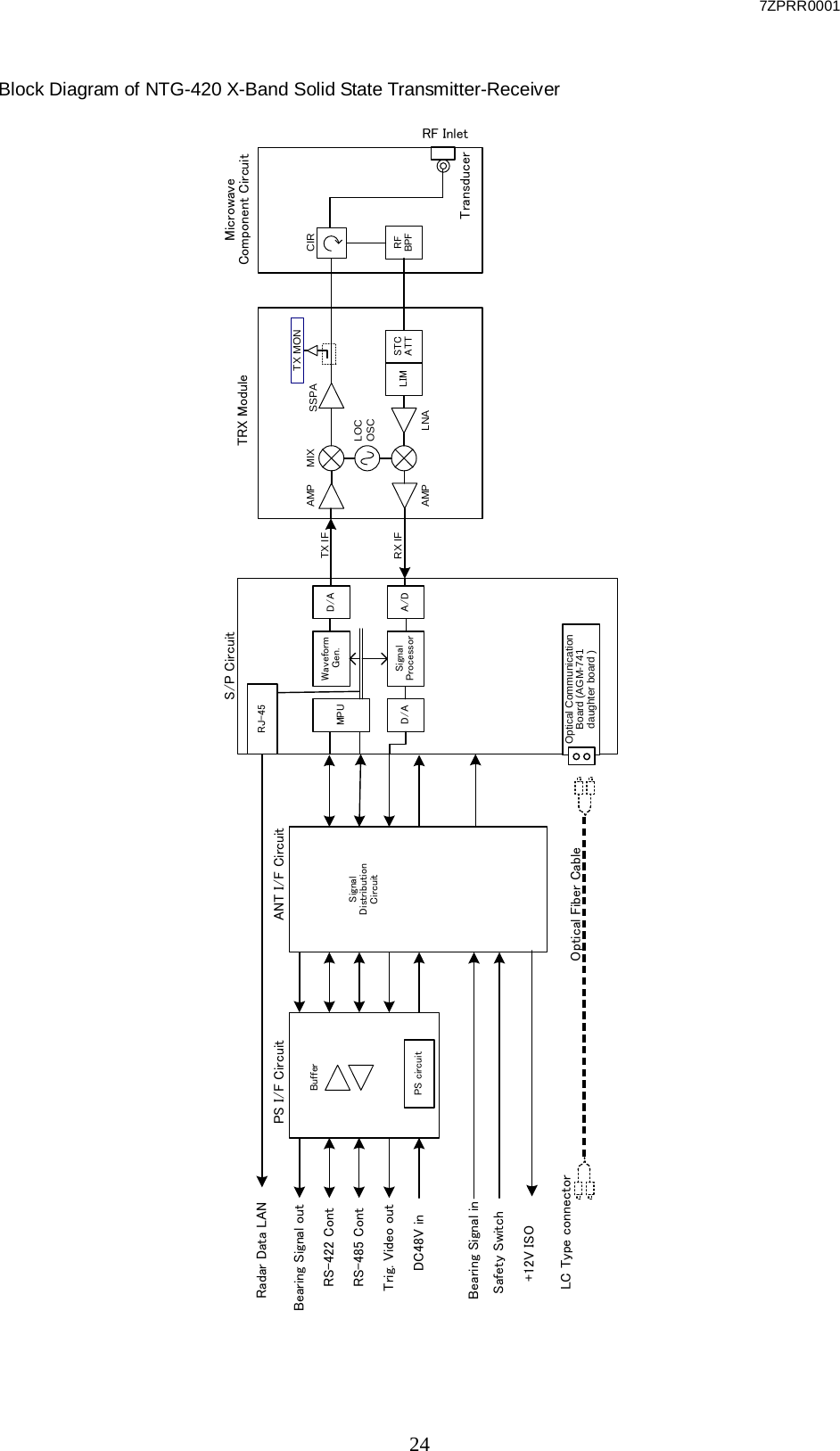
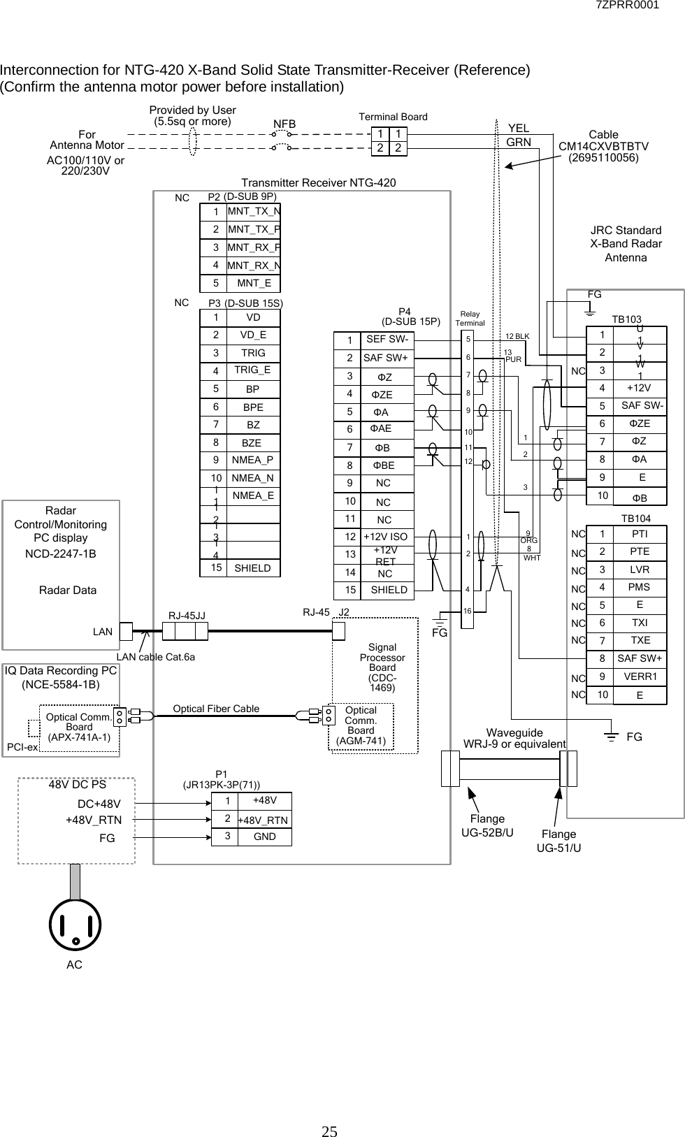
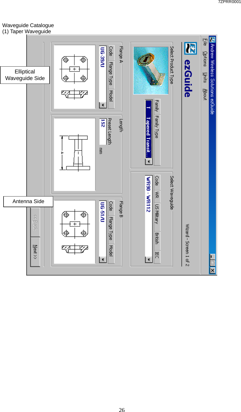
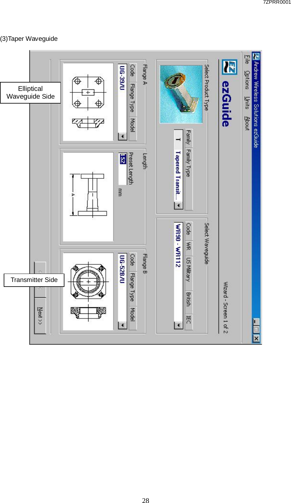
Usera manual(Installation)