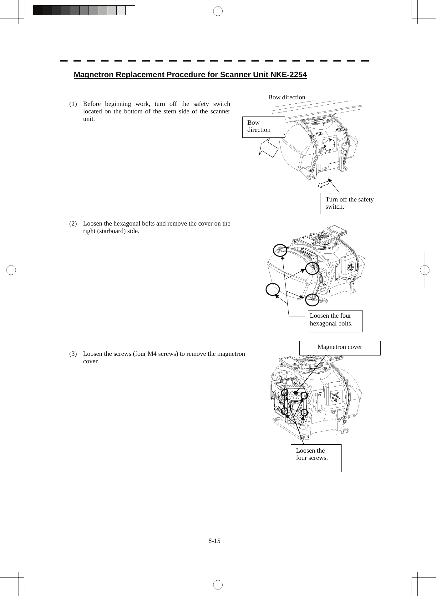
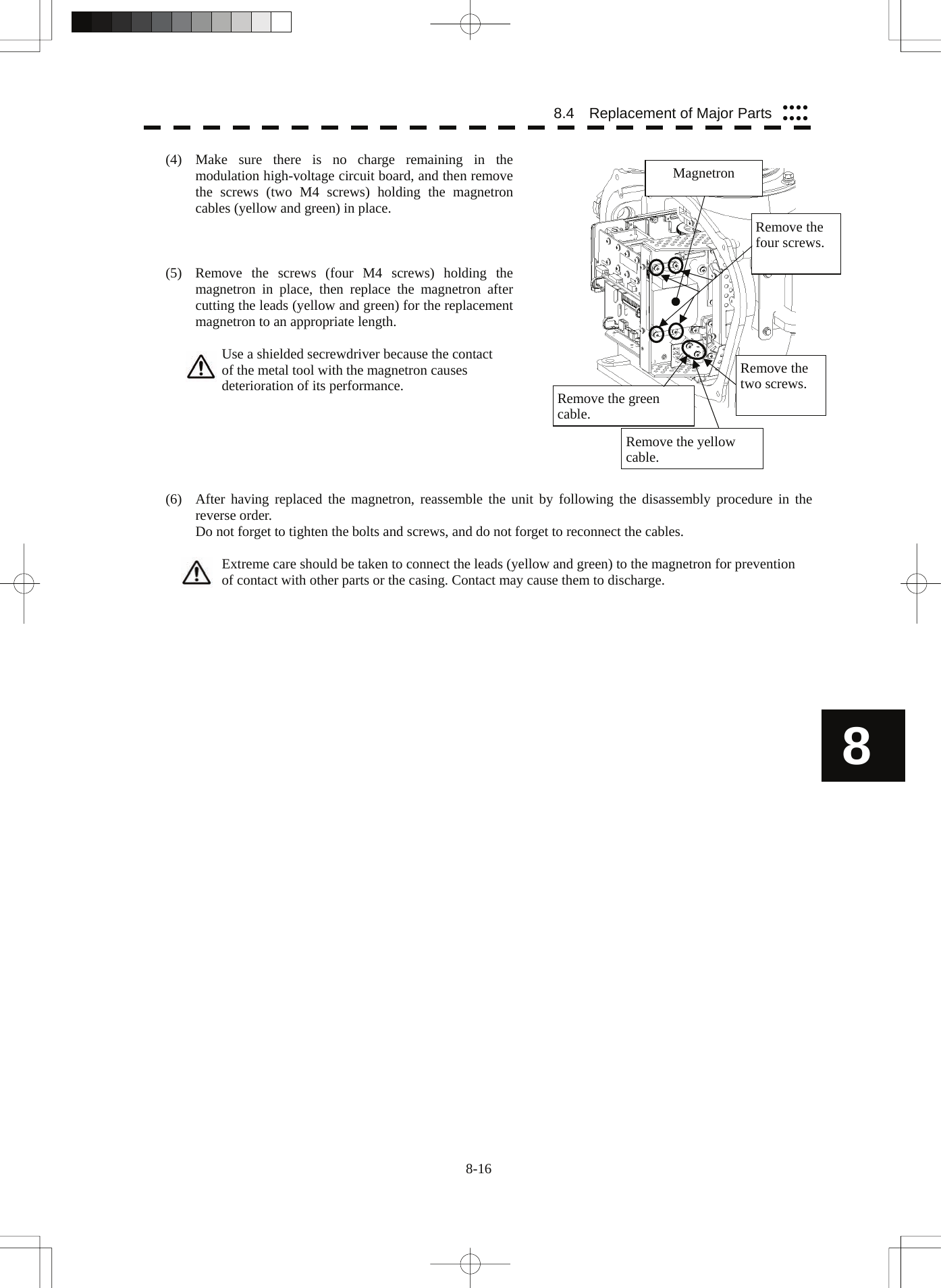
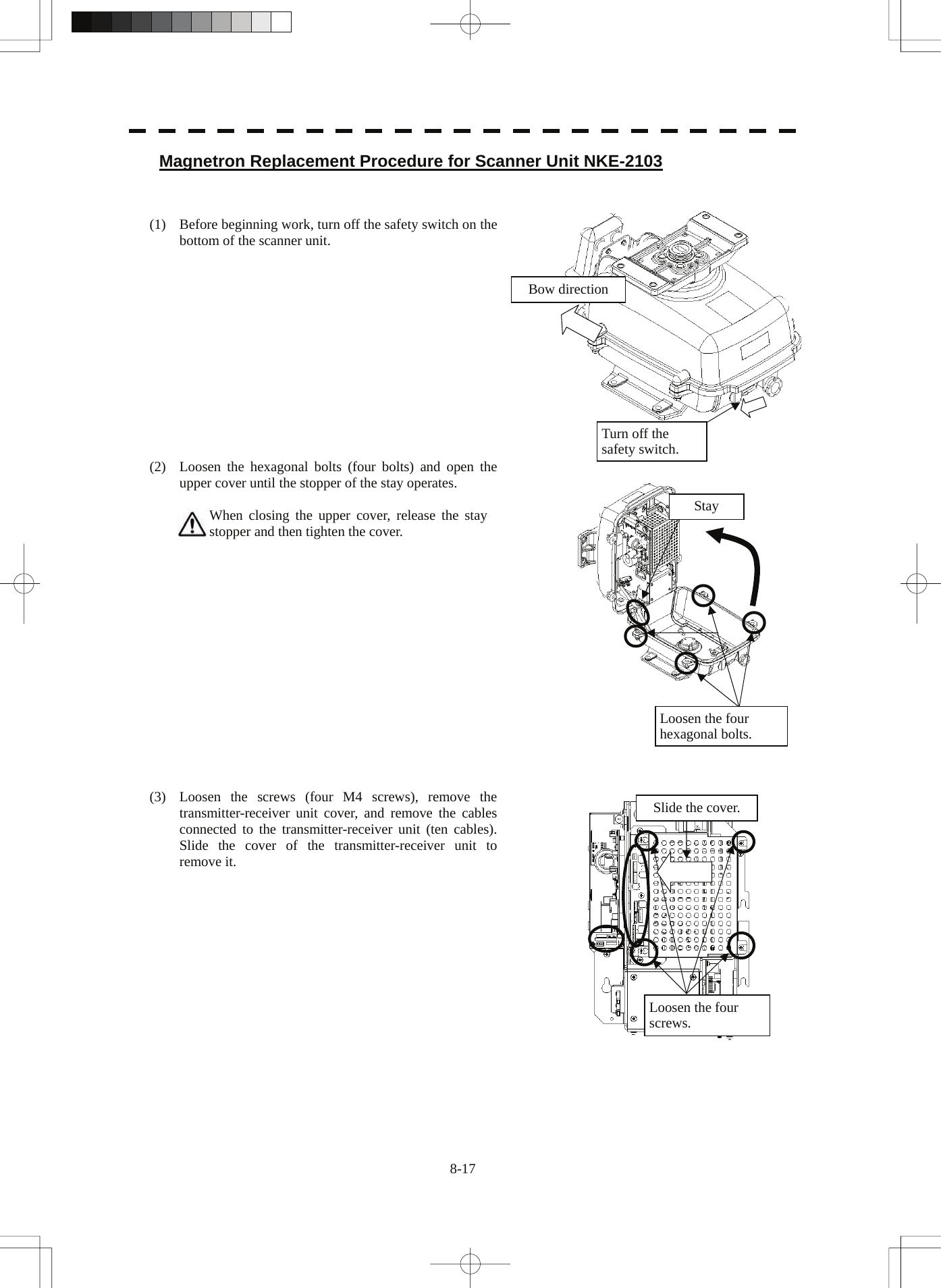
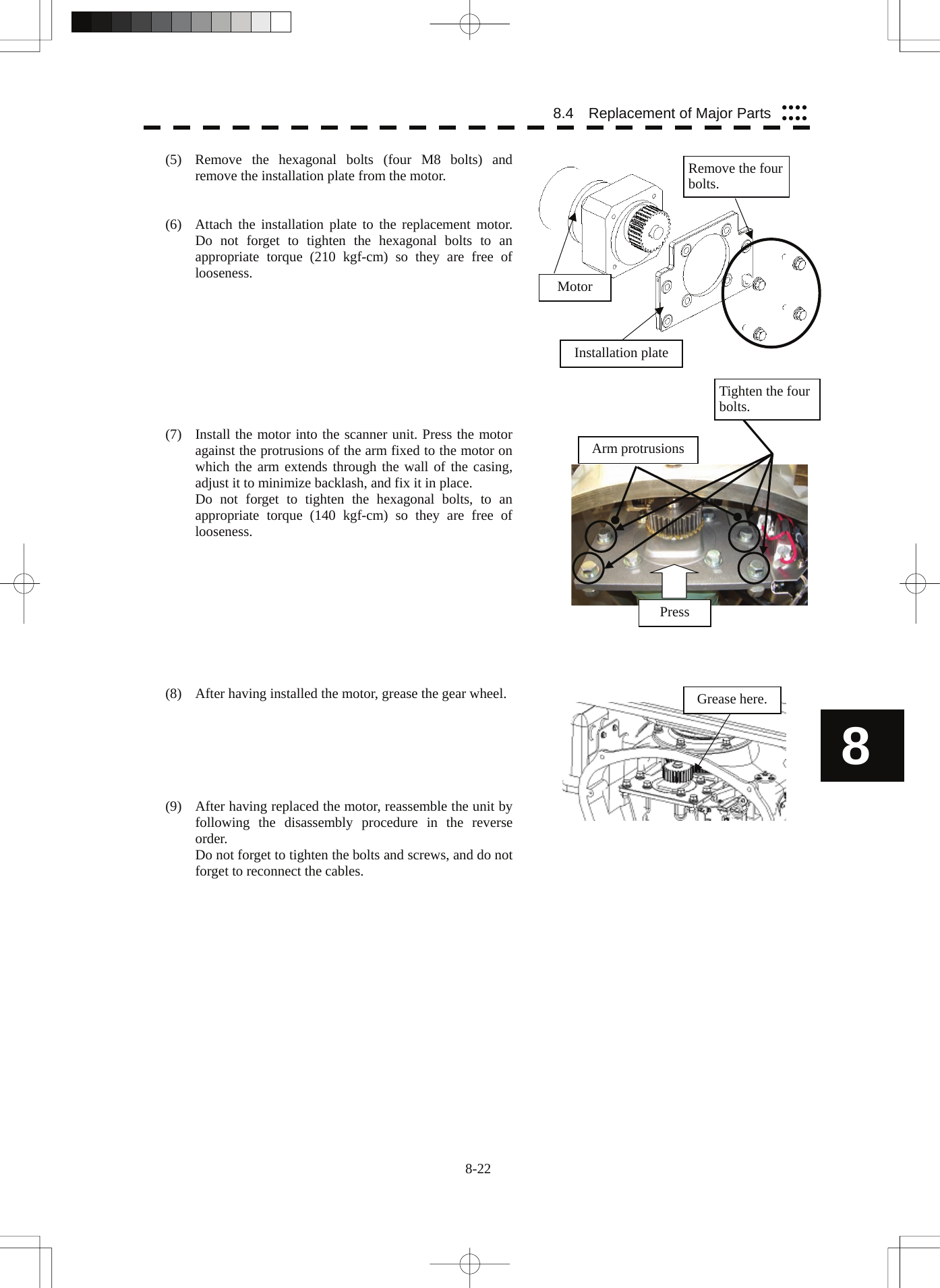
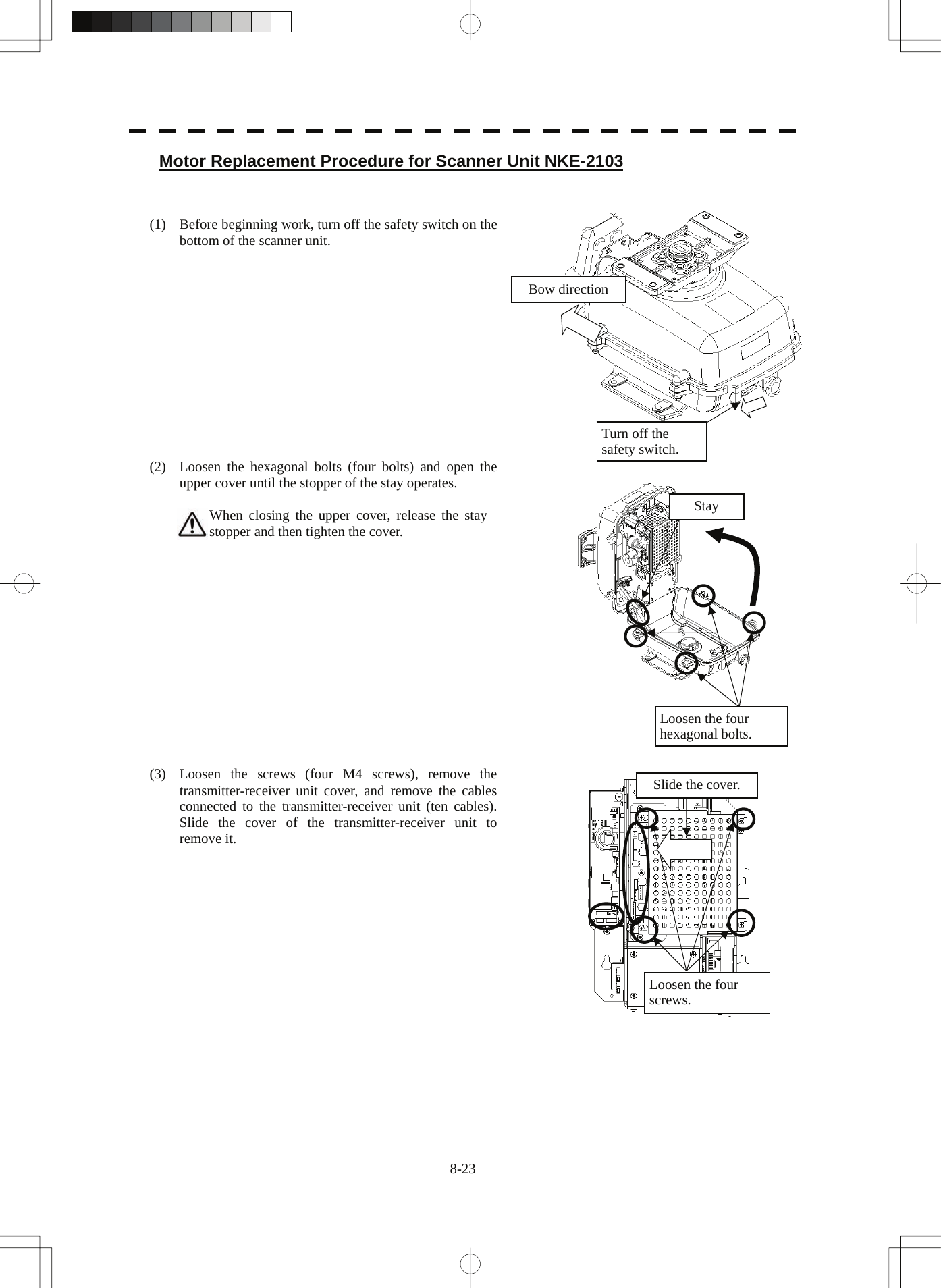
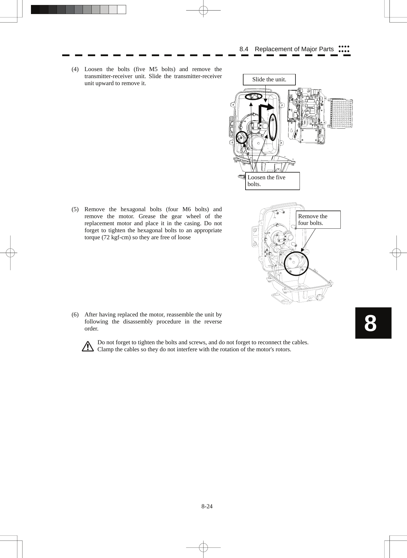
Japan Radio NKE2254 Marine Radar User Manual
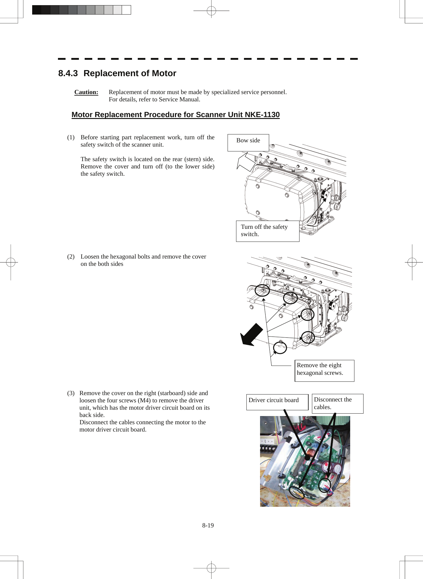
Japan Radio Co Ltd. Marine Radar Users Manual
UserManual.wiki
>
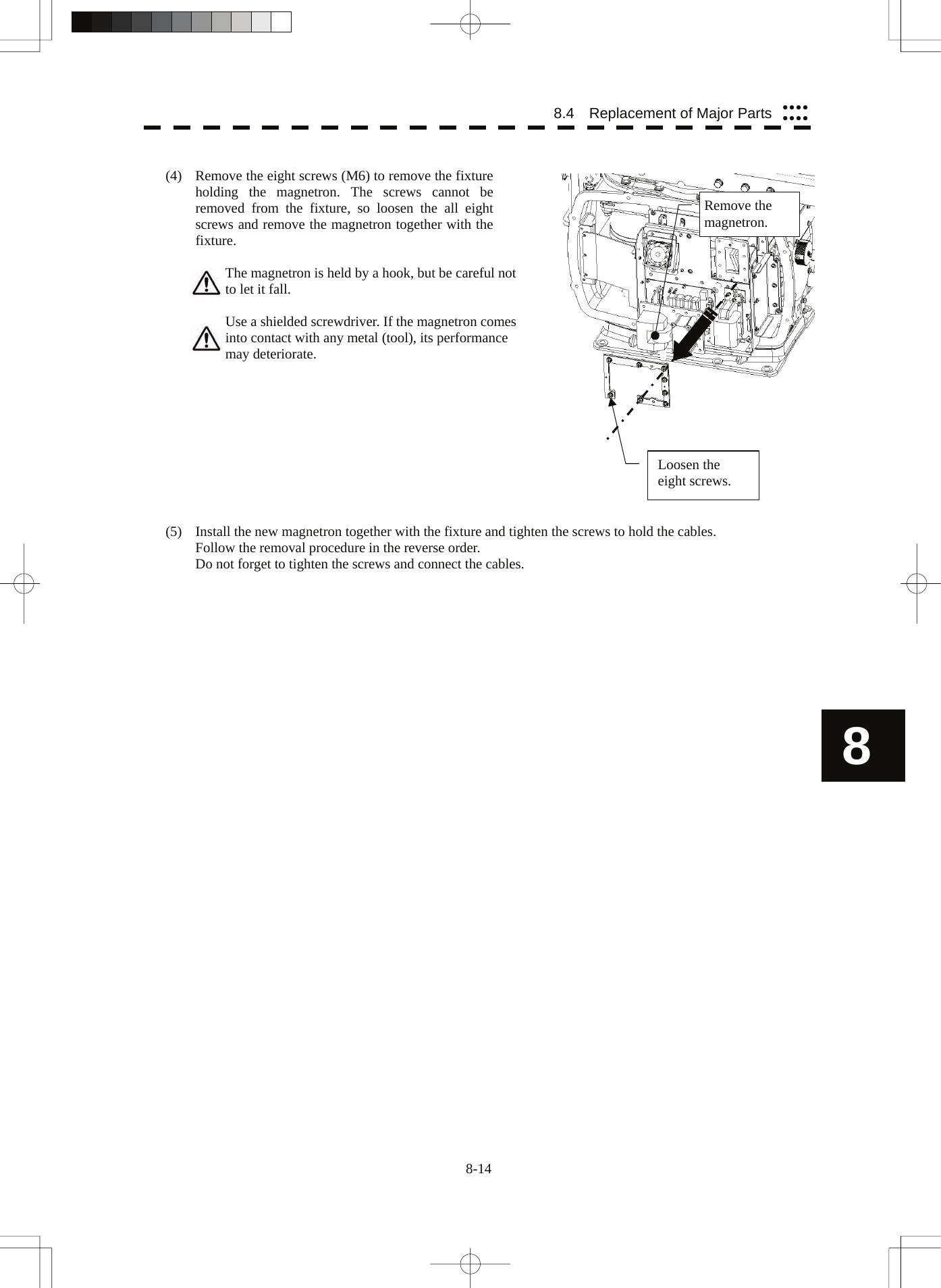
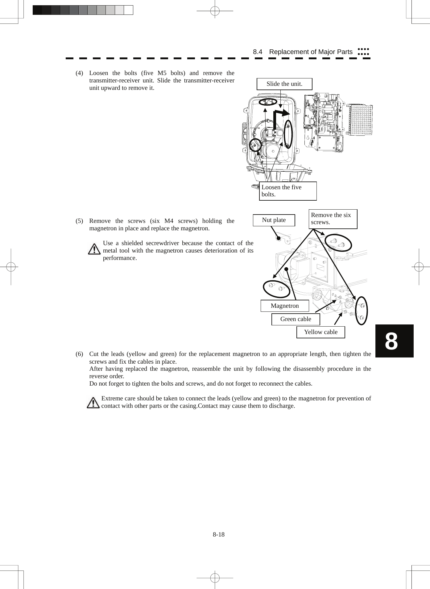
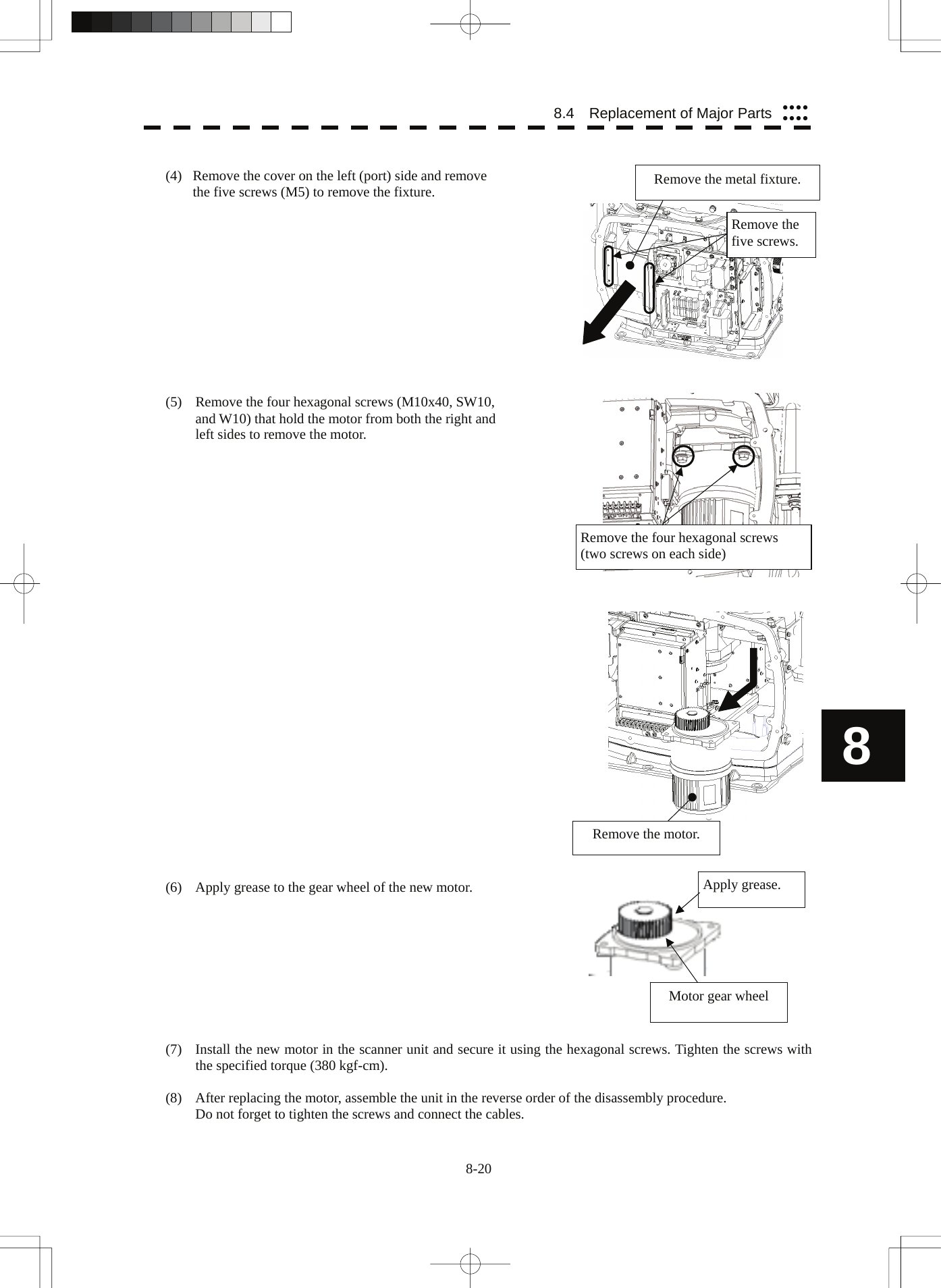
Japan Radio
>
NKE2254 User Manual
>
Users Manual 4
Contents
1.
Users Manual 1
2.
Users Manual 2
3.
Users Manual 3
4.
Users Manual 4
5.
Users Manual
Users Manual 4
Navigation menu
Upload a User Manual
Namespaces
Wiki Guide
HTML
PDF
Info
Views
User Manual
Discussion / Help
Navigation
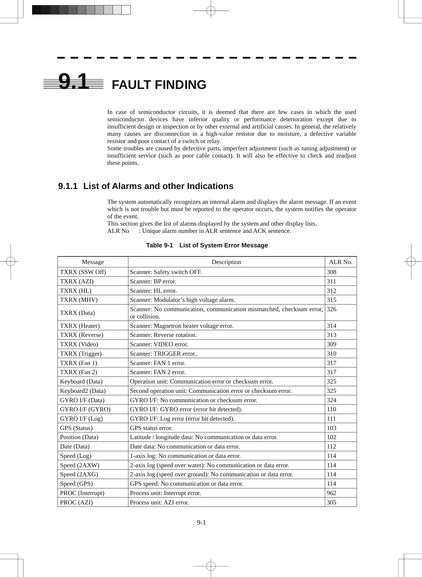
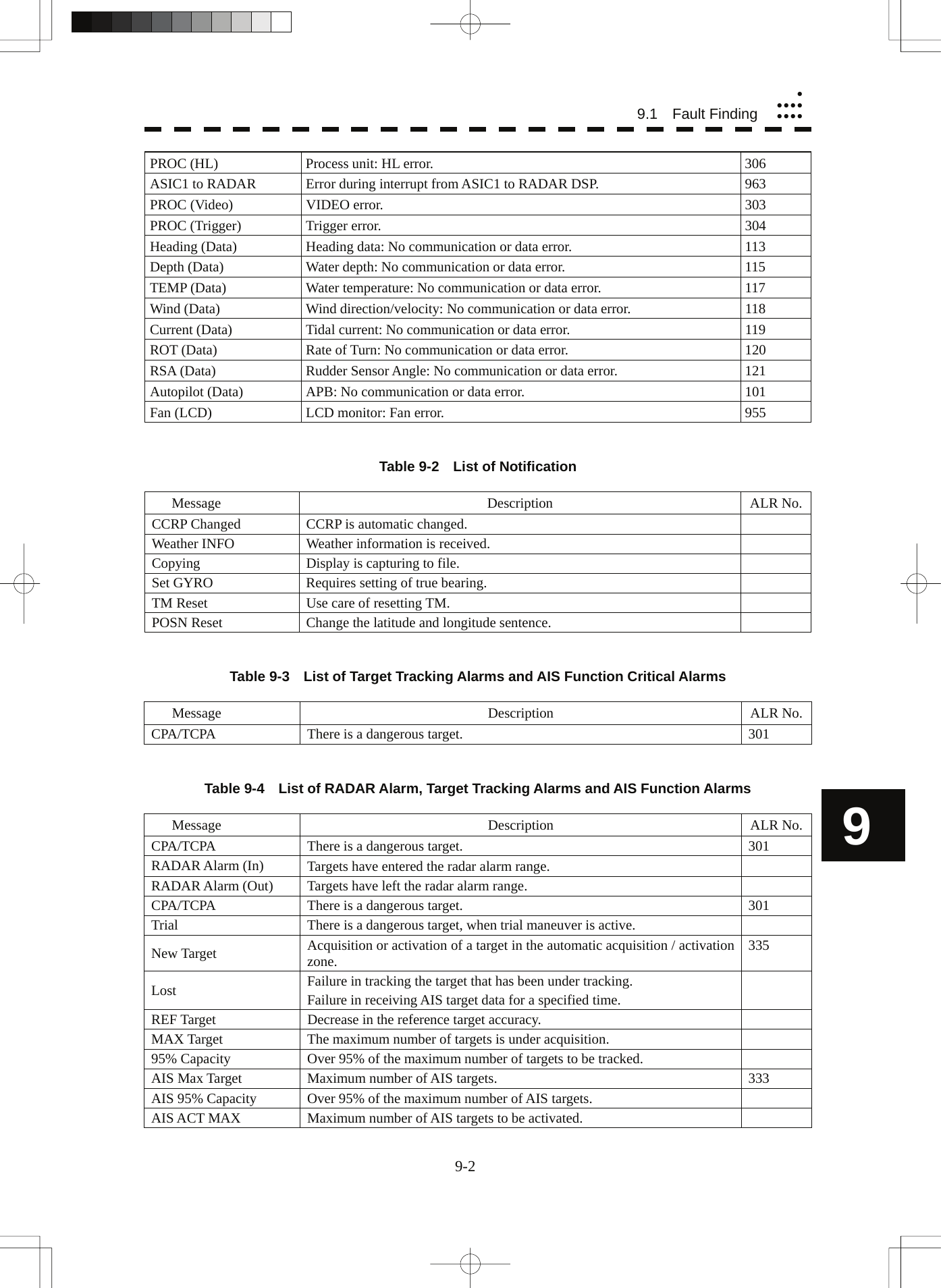
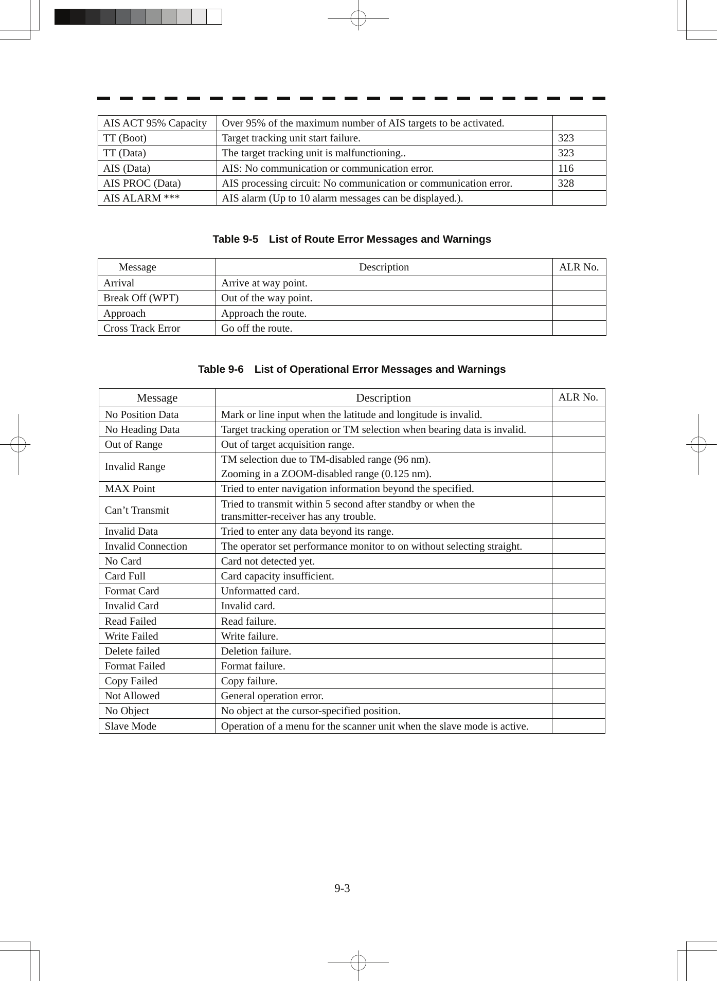
![8.3 Performance Check yyyyyyyy8.3 PERFORMANCE CHECK Make operational check on the radar equipment regularly and if any problem is found, investigate it immediately. Pay special attention to the high voltage sections in checking and take full care that no trouble is caused by any error or carelessness in measurement. Take note of the results of checking, which can be used effectively in the next check work. Operational check shall be made in accordance with Table 8-1 Function Check List in the order as specified in it. Table 8-1 Check List Equipment Item to be checked Criteria Remarks Transmitter-receiver Unit Tuning LED of Receiver The LED is lighting during operation 48NM range Video and echoes on the screen Sensitivity LCD brilliance can be controlled correctly Various markers Various numerical indications Lighting Can be correctly controlled Memory See section 8.3.1 [I]-[1]. Communications Lines See section 8.3.1 [I]-[3]. Power Supply, Backup Battery See section 8.3.1 [I]-[4]. Monitor See section 8.3.1 [II]. Operation Unit See section 8.3.1 [III]. System Alarm Log Display See section 8.3.1 [V]. System Information Display See section 8.3.1 [VI]. Magnetron current See section 8.3.1 [VII]. Display Unit Target Tracking See section 5.2.7. Signals from the Scanner Unit See section 8.3.1 [I]-[2]. Scanner Unit Performance Monitor See section 8.3.1 [IV]. 8 8-6](https://usermanual.wiki/Japan-Radio/NKE2254.Users-Manual-4/User-Guide-993477-Page-8.png)
![8.3.1 Check Performance on Test Menu The radar operating state can be checked by opening the Test Menu. Procedures 1. Perform the following menu open procedure to open the Test Menu. Main → 9. NEXT → 9. Test Menu 2. Select the items to be checked. The list of check items will appear. 1. Self Test [I] Self-diagnostic function 2. Monitor Test [II] Monitor check 3. Keyboard Test [III] Operation unit check 4. MON Display [IV] Performance monitor 5. System Alarm Log [V] Error log display 6. System Information [VI] System information display Magnetron Current [VII] Indication of magnetron current 3. Select the items to be checked. The list of check items will appear. [I] Self-diagnosis function (Self Test) Check of memory, scanner unit, and communications Lines 1. Memory Test [1] Memory check 2. TXRX Test [2] Scanner check 3. Line Test [3] Communication line check 4. Supply Voltage [4] Supply voltage check [1] Memory Test Checks for the performance of built-in memory. 1. SDRAM [1] SDRAM check 2. SRAM [2] SRAM check 3. FLASH ROM [3] Flash ROM check 4. GRAPHIC [4] Graphic check When no abnormality is found, OK is displayed. When an abnormality is found, NG is displayed. 8-7](https://usermanual.wiki/Japan-Radio/NKE2254.Users-Manual-4/User-Guide-993477-Page-9.png)
![8.3 Performance Check yyyyyyyy [2] TXRX Test Checks for signals from the scanner. Safety Switch Scanner’s safety switch check AZI Pulse Scanner rotation signal check HL Pulse Heading line signal check MH Current Check on the load current of high voltage in the modulator Trigger Radar trigger signal check Video Radar video check When no abnormality is found, OK is displayed. When an abnormality is found, NG is displayed. In standby, ** will appear. [3] Check of Communication Lines (Line Test) Check the status of communications with options. TXRX Check on connection with the transmitter-receiver SIG.PROC Check on connection with the signal processing circuit TT Check on connection with the target tracking unit GYROO I/F Check on connection with the GYRO I/F unit GPS Compass Check on connection with the GPS compass ISW Check on connection with the interswitch Plotter Key Check on connection with the plotter option When no abnormality is found, OK is displayed. When an abnormality is found, NG is displayed. The status display field of equipment not connected is left blank. 8 [4] Supply Voltage Check the voltage of internal power supply. Item Normal value 12V 11.00 to 12.20V 5V 4.75 to 5.25V 3.3V 3.14 to 3.46V Battery 2.50V or more 8-8](https://usermanual.wiki/Japan-Radio/NKE2254.Users-Manual-4/User-Guide-993477-Page-10.png)
![[II] Monitor Test Checks for the display. The test pattern will be shown on the display. Pattern 1 All colors are filled with white. Pattern 2 A white box is displayed on the black background of 1280 × 1024 dots. Pattern 3 Displays rectangle × 2, circle × 2, and cross-shape× 13 (white lines on the black background). Pattern 4 Displays “H” of 9 dots × 9 dots on the entire screen (white character on the black background). Pattern 5 Gray scale display (16 levels) Pattern 6 Displays a color bar. Pattern 7 Displays the VDR test pattern. Pattern 8 Displays the specified color. To return to the normal display, press any key. If errors occur in the monitor, no test pattern will appear. [III] Keyboard Test (Operation Unit Test) Checks for the controls and switches of the operation panel. 1. Key Test [1] Key check 2. Buzzer Test [2] Buzzer check 3. Light [3] Control panel light check [1] Key Test Checks for the controls and switches of the operation panel. Each key on the operation panel on the display is shown in reverse video at the same time the key is pressed, and the name of the pressed key is displayed. [2] Buzzer Test Checks for the operation panel buzzer. The buzzer will sound. The buzzer automatically stops after it sounds for a specified length of time. [3] Light Test Checks for the control panel light. The brightness of the operation panel is gradually intensified at four levels. [IV] Check of the Performance Monitor (MON Display) Displays the performance monitor status. * Transmitter System Transmitter system attenuation value check. Attenuation Value * Receiver System Receiver system attenuation value check. MON Pattern Range Attenuation Value Turn the [VRM] dial to make adjustments so that the farthest point of the performance monitor pattern. The attenuation value of receiver system is displayed. 8-9](https://usermanual.wiki/Japan-Radio/NKE2254.Users-Manual-4/User-Guide-993477-Page-11.png)
![8.3 Performance Check yyyyyyyy[V] System Alarm Log display Displays previously occurred system errors with the dates and times when they occurred. The current error is displayed at the lower right of the radar display. For details, refer to Chapter 9. The Error log display button (2-29P Alarm) is clicked, in the same way as that one. To erase the alarm logs, press the All Clear button in the log display window. [VI] System INFO Displays the current system information. Indicator Processor software version information TXRX Scanner software version information System No. System number TX Time Total magnetron transmitting time (Total time during which radar was transmitted) X-Band S-Band Motor Time Total operating time (Total power-on time) TXRX Total Time Total operating time of the scanner unit (Total power-on time of the antenna unit) Total Time Total operating time of the display unit (Total power-on time of the display unit) [VII] Magnetron Current 8 Displays the Magnetron Current bar indicating the magnetron current to check. When a 48 NM range is set, the magnetron current is normal if the Magnetron Current bar reads the value below. 10 kW: 4 to 7 scale marks 25/30 kW: 5 to 8 scale marks 8-10](https://usermanual.wiki/Japan-Radio/NKE2254.Users-Manual-4/User-Guide-993477-Page-12.png)
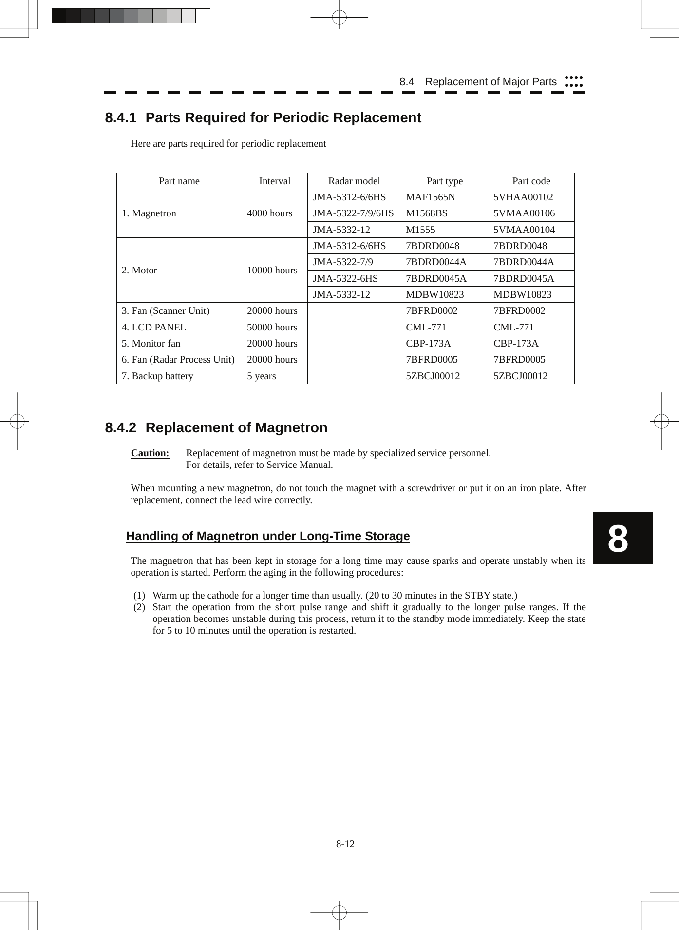

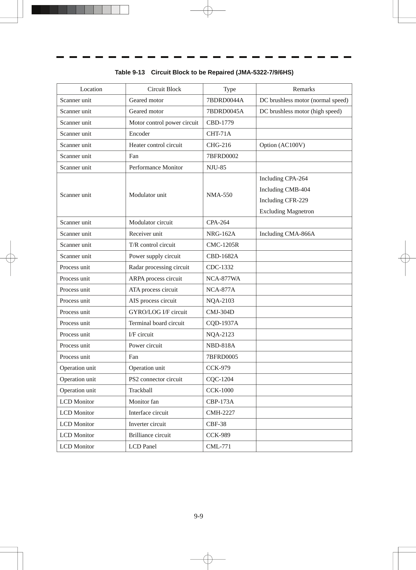
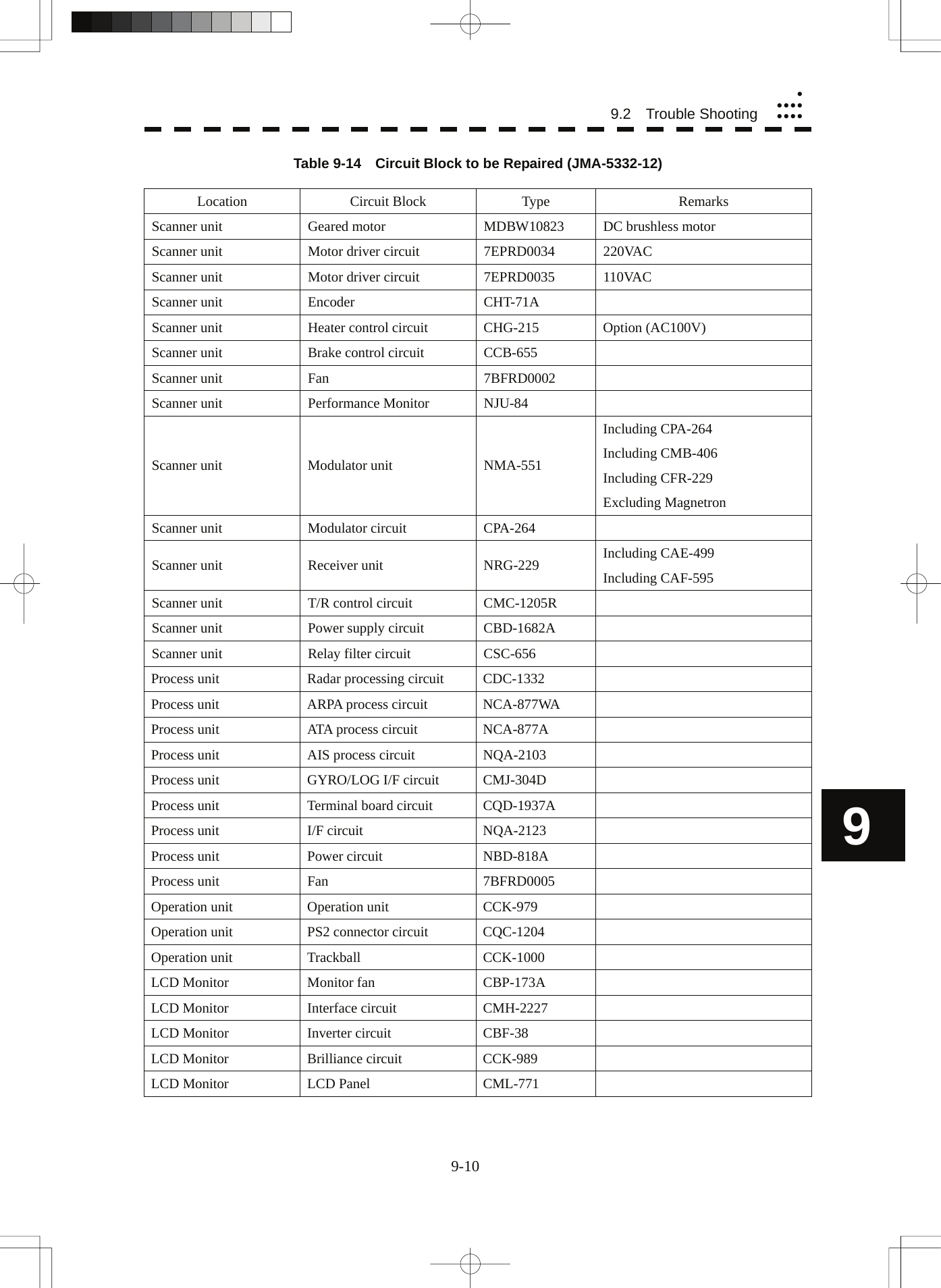
![Table 9-11 Special Parts [I] JMA-5312-6/6HS Parts No. Name Type Manufacturer Location Code V101 Magnetron MAF1565N NJRC Scanner unit 5VHAA00102 A101/A102 Circulator FCX68R Toshiba Scanner unit 5AJIX00027 A103 Dummy NJC4002 NJRC Scanner unit 5ANDF00001 A104 Filter NJC9952 NJRC Scanner unit 5AWAX00002 A301 Diode Limiter NJS6930 NJRC Scanner unit 5ATBT00006 [II] JMA-5322-7/9/6HS Parts No. Name Type Manufacturer Location Code V101 Magnetron M1568BS NJRC Scanner unit 5VMAA00106 A101/A102 Circulator NJC3901M NJRC Scanner unit 5AJBV00007 A103 Dummy NJC4002 NJRC Scanner unit 5ANDF00001 A104 Filter NJC9952 NJRC Scanner unit 5AWAX00002 A301 Diode Limiter NJS6930 NJRC Scanner unit 5ATBT00006 [III] JMA-5332-12 Parts No. Name Type Manufacturer Location Code V101 Magnetron M1555 NJRC Scanner unit 5VMAA00104 A101 Circulator NJC3316 NJRC Scanner unit 5AJBV00008 A301 Diode Limiter NJS6318 NJRC Scanner unit 5ATBT00005 9-7](https://usermanual.wiki/Japan-Radio/NKE2254.Users-Manual-4/User-Guide-993477-Page-37.png)

![11.4 Scanner (NKE-2103-6)yyyyyyyyyyy11.4 SCANNER (NKE-2103-6) (1) Dimensions Height 457mm×Swing Circle 1910mm (2) Mass Approx. 40kg (3) Polarization Horizontal Polarization (4) Directional Characteristic Horizontal Beam Width: 1.2° (-3dB width) Vertical Beam Width: 20° (-3dB width) Sidelobe Level: Below –26dB (within ±10°) Below –30dB (outside ±10°) (5) Revolution Approx. 27rpm (Normal) (6) Peak Power 10kW±50% (7) Transmitting Frequency 9410 ±30MHz (8) Transmitting Tube Magnetron [MAF1565N] (9) Pulse width/Repetition Frequency SP1:0.08uS/2250Hz MP1:0.25uS/1700Hz,MP2:0.5uS/1200Hz LP1:0.8uS/750Hz,LP2:1.0uS/650Hz 0.125NM SP1 0.25NM SP1 0.5NM SP1 0.75NM SP1 / MP1 1.5NM SP1 / MP1 / MP2 3NM MP1 / MP2 / LP1 6NM MP1 / MP2 / LP1 / LP2 12NM MP1 / MP2 / LP1 / LP2 24NM MP2 / LP1 / LP2 48NM LP2 96NM LP2 (10) Duplexer Circulator + Diode Limiter (11) Mixer MIC Front End (12) Intermediate Frequency Amplifier Intermediate Frequency: 60MHz Band Width: 20MHz(0.08μS) 6MHz(0.25μS,0.5μS) 3MHz(0.8μS, 1μS) 11 Gain: More than 90dB Amplifying Characteristics: Logarithmic Amplifier (13) Overall Noise Figure 7.5dB(Average) 11-4](https://usermanual.wiki/Japan-Radio/NKE2254.Users-Manual-4/User-Guide-993477-Page-52.png)
![11.5 SCANNER (NKE-2254-7/9) (1) Dimensions 25kW-7ft: Height 536mm×Swing Circle 2270mm 25kW-9ft: Height 536mm×Swing Circle 2825mm (2) Mass 25kW-7ft: Approx. 58 kg 25kW-9ft: Approx. 60 kg (3) Polarization Horizontal Polarization (4) Directional Characteristics Horizontal Beam Width: 1.0° (7ft, -3dB width) 0.8° (9ft, -3dB width) Vertical Beam Width 20° (7/9ft, -3dB width) Sidelobe Level: Below –26dB (7/9ft, within ±10°) Below –30dB (7/9ft, outside ±10°) (5) Revolution 24rpm (7/9ft, Normal) (6) Peak Power 25kW ±50% (7) Transmitting Frequency 9410 ±30MHz (8) Transmitting Tube Magnetron [M1568BS] (9) Pulse Width/Repetition Frequency SP1:0.07uS/2250Hz MP1:0.2uS/2250Hz,MP2:0.3uS/1900Hz,MP3:0.4uS/1400Hz LP1:0.8uS/750Hz,LP2:1.0uS/650Hz,LP3:1.2uS/510Hz 0.125NM SP1 0.25NM SP1 0.5NM SP1 0.75NM SP1 / MP1 1.5NM SP1 / MP1 / MP2 / MP3 3NM MP1 / MP2 / MP3 / LP1 6NM MP1 / MP2 / MP3 / LP1 / LP2 12NM MP1 / MP2 / MP3 / LP1 / LP2 24NM MP3 / LP1 / LP2 48NM LP2 96NM LP3 (10) Duplexer Circulator + Diode Limiter (11) Mixer MIC Front End (12) Intermediate Frequency Amplifier Intermediate Frequency: 60MHz Band Width: 25MHz(0.07μS) 8MHz(0.2μS, 0.3μs, 0.4μS) 3MHz(0.8μS, 1μS, 1.2μS) Gain: More than 90dB Amplifying Characteristics: Logarithmic Amplifier (13) Overall Noise Figure 7.5dB(Average) 11-5](https://usermanual.wiki/Japan-Radio/NKE2254.Users-Manual-4/User-Guide-993477-Page-53.png)
![11.7 SCANNER (NKE-2103-6HS) (1) Dimensions Height 457mm×Swing Circle 1910mm (2) Mass Approx. 40kg (3) Polarization Horizontal Polarization (4) Directional Characteristic Horizontal Beam Width: 1.2° (-3dB width) Vertical Beam Width: 20° (-3dB width) Sidelobe Level: Below –26dB (within ±10°) Below –30dB (outside ±10°) (5) Revolution Approx. 48rpm (6) Peak Power 10kW±50% (7) Transmitting Frequency 9410 ±30MHz (8) Transmitting Tube Magnetron [MAF1565N] (9) Pulse width/Repetition Frequency SP1:0.08uS/2250Hz MP1:0.25uS/1700Hz,MP2:0.5uS/1200Hz LP1:0.8uS/750Hz,LP2:1.0uS/650Hz 0.125NM SP1 0.25NM SP1 0.5NM SP1 0.75NM SP1 / MP1 1.5NM SP1 / MP1 / MP2 3NM MP1 / MP2 / LP1 6NM MP1 / MP2 / LP1 / LP2 12NM MP1 / MP2 / LP1 / LP2 24NM MP3 / LP1 / LP2 48NM LP2 96NM LP2 (10) Duplexer Circulator + Diode Limiter (11) Mixer MIC Front End (12) Intermediate Frequency Amplifier Intermediate Frequency: 60MHz Band Width: 20MHz(0.08μS) 6MHz(0.25μS,0.5μS) 3MHz(0.8μS, 1μS) Gain: More than 90dB Amplifying Characteristics: Logarithmic Amplifier (13) Overall Noise Figure 7.5dB(Average) 11-7](https://usermanual.wiki/Japan-Radio/NKE2254.Users-Manual-4/User-Guide-993477-Page-55.png)
![11.8 Scanner (NKE-2254-6HS)yyyyyyyyyyy11.8 SCANNER (NKE-2254-6HS) (1) Dimensions 25kW-6ft: Height 536mm×Swing Circle 1910mm (2) Mass Approx. 55 kg (3) Polarization Horizontal Polarization (4) Directional Characteristics Horizontal Beam Width: 1.2° Vertical Beam Width 20° (-3dB width) Sidelobe Level: Below –26dB (within ±10°) Below –30dB (outside ±10°) (5) Revolution 48rpm (Normal) (6) Peak Power 25kW ±50% (7) Transmitting Frequency 9410 ±30MHz (8) Transmitting Tube Magnetron [M1568BS] (9) Pulse Width/Repetition Frequency SP1:0.07uS/2250Hz MP1:0.2uS/2250Hz,MP2:0.3uS/1900Hz,MP3:0.4uS/1400Hz LP1:0.8uS/750Hz,LP2:1.0uS/650Hz,LP3:1.2uS/510Hz 0.125NM SP1 0.25NM SP1 0.5NM SP1 0.75NM SP1 / MP1 1.5NM SP1 / MP1 / MP2 / MP3 3NM MP1 / MP2 / MP3 / LP1 6NM MP1 / MP2 / MP3 / LP1 / LP2 12NM MP1 / MP2 / MP3 / LP1 / LP2 24NM MP3 / LP1 / LP2 48NM LP2 96NM LP3 (10) Duplexer Circulator + Diode Limiter (11) Mixer MIC Front End (12) Intermediate Frequency Amplifier Intermediate Frequency: 60MHz Band Width: 25MHz(0.07μS) 8MHz(0.2μS, 0.3μS, 0.4μS) 3MHz(0.8μS, 1μS, 1.2μS) 11 Gain: More than 90dB Amplifying Characteristics: Logarithmic Amplifier (13) Overall Noise Figure 7.5dB(Average) 11-8](https://usermanual.wiki/Japan-Radio/NKE2254.Users-Manual-4/User-Guide-993477-Page-56.png)
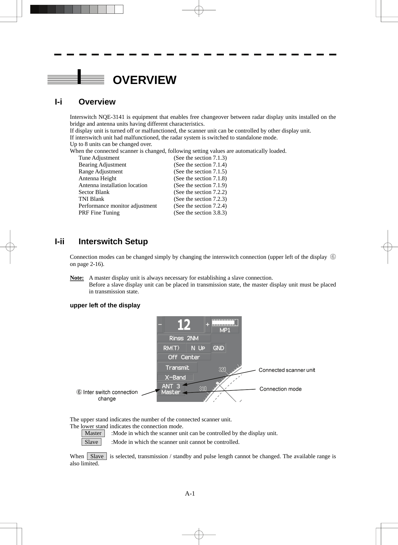
![A-3 II-ii Inter Switch Menu The Inter Switch Menu can be opened only when the transmission standby state. Procedures 1 Press the [STBY] key. The transmission standby state will be placed. 2 Move the cursor onto the Interswitch connection change (upper left of the display ⑥ on page 2-16), and press the [ENT] key. The Inter Switch Menu will appear. Exit 1 Press the [0] key. The Inter Switch Menu will close.](https://usermanual.wiki/Japan-Radio/NKE2254.Users-Manual-4/User-Guide-993477-Page-73.png)
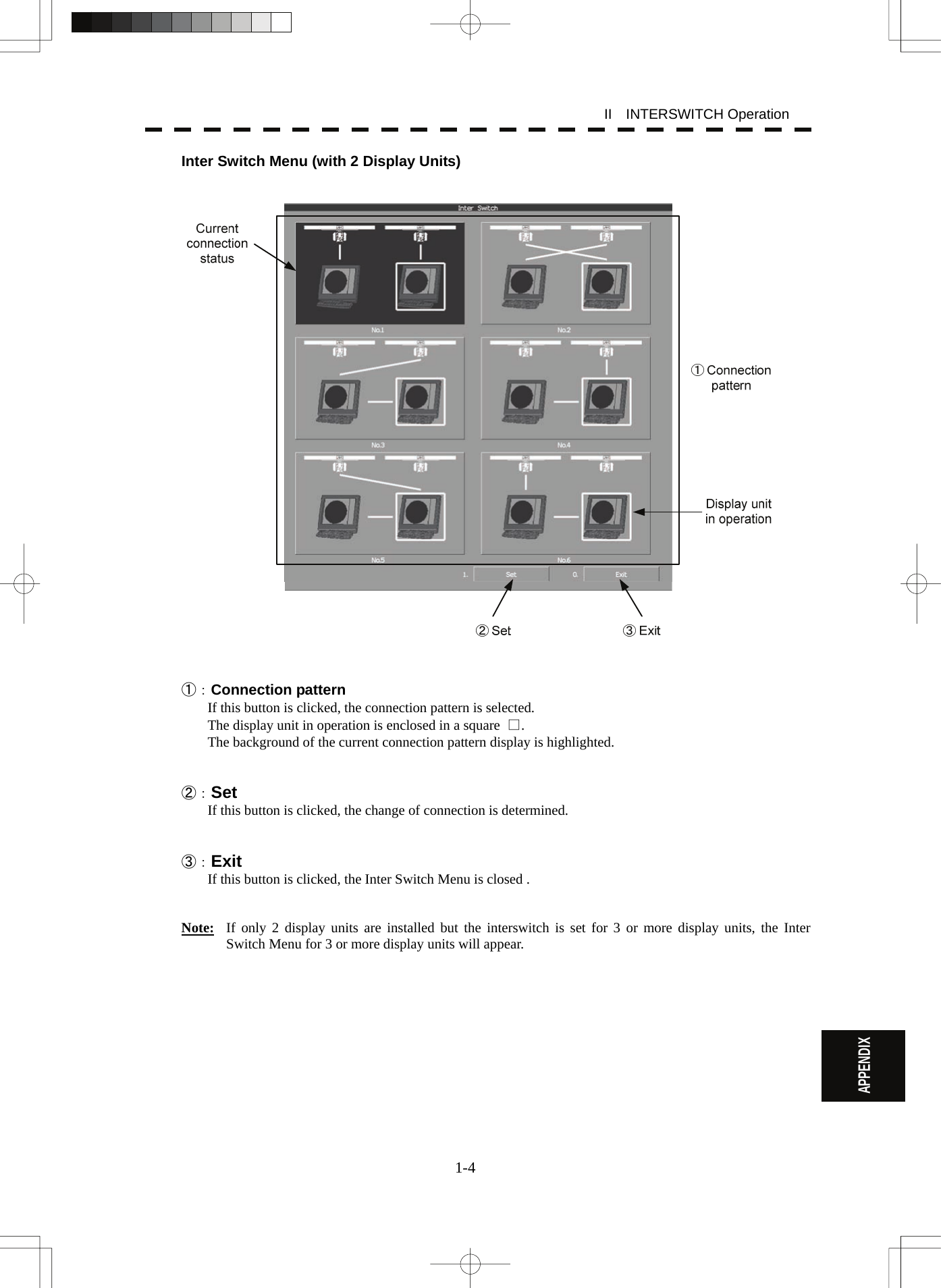
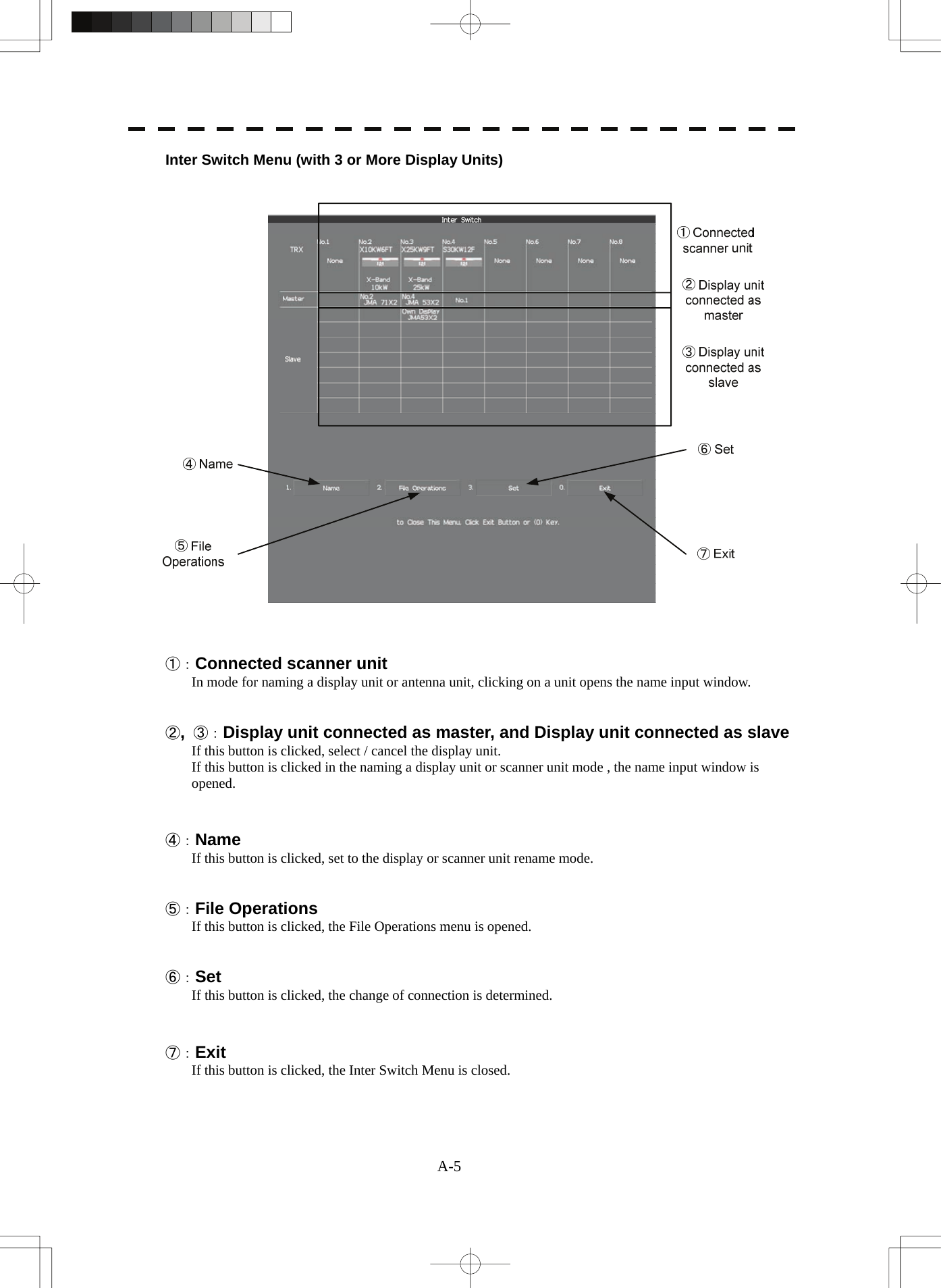
![1-6 II INTERSWITCH Operation APPENDIX II-iii Change of Connection Pattern (with 2 Display Units) If two display units are installed, a connection pattern needs to be selected. Procedures 1 Open the Inter Switch menu (with 2 Display Units). 2 Move the cursor onto the Connection pattern (Inter Switch Menu ① on page A-4) to be changed , and press the [ENT] key. The connection pattern will be selected, and Set (in Inter Switch Menu ② on page A-4) will blink. 3 Press the [3] key. The connection pattern will be changed. II-iv Change of Connection Pattern (with 3 or More Display Units) If three or more display units are installed, the layout of connection patterns needs to be set. Procedures 1 Open the Inter Switch Menu (with 3 or More Display Units). 2 Move the cursor onto the display unit (Inter Switch Menu ②/③ on page A-5) to be changed , and press the [ENT] key. The selected display unit will be highlighted. To deselect the display unit, press the [ENT] key again. 3 Move the cursor to the change-destination display unit, and press the [ENT] key. The selected display unit in step 2 will be switched to the change-destination display unit, and Set (Inter Switch Menu ⑥ on page A-5) will blink. If the change destination is empty, control will move and Set will blink. 4 Press the [3] key. The connection pattern will be changed. Note: A master display unit is always necessary for establishing a slave connection.](https://usermanual.wiki/Japan-Radio/NKE2254.Users-Manual-4/User-Guide-993477-Page-76.png)
![A-7 II-v Operating Connection Pattern Files (File Operations) Frequently used connection patterns can be read easily by saving interswitch connection patterns. [I] Loading connection patterns (Load) Procedures 1 Open the Inter Switch Menu (with 3 or More Display Units). 2 Press the [2] key. The File Operations menu will appear. 3 Press the [1] key. Currently saved connection patterns in memory will be listed. 4 Press the [numeric] key corresponding to the file to be loaded. Confirmation Window will appear. 5 Press the [1] key. The connection pattern will be changed. [II] Saving connection patterns (Save) Procedures 1 Open the Inter Switch Menu (with 3 or More Display Units). 2 Press [2] key. The File Operations window will appear. 3 Press [2] key. The Save menu will appear. Currently saved connection patterns in memory will be listed. 4 Press the [numeric] key corresponding to the file to be saved. The Input File Name window will appear. 5 Enter the file name to be saved. Up to 8 characters can be entered. For the input method on the character input screen, see Section 3.3.4. The connection pattern will be saved when the name is input.](https://usermanual.wiki/Japan-Radio/NKE2254.Users-Manual-4/User-Guide-993477-Page-77.png)
![1-8 II INTERSWITCH Operation APPENDIX [III] Erasing a connection pattern (Erase) Procedures 1 Open the Inter Switch Menu (with 3 or More Display Units). 2 Press the [2] key. The File Operations window will appear. 3 Press the [3] key. The Erase menu will appear. The list of connection patterns stored in the memory will be displayed. 4 Press the [numeric] key corresponding to the file to be erased. Confirmation Window will appear. 5 Press the [1] key. The selected connection pattern is erased and the file name is deleted from the list. II-vi Names of Display Units and Scanner Units The display units and antenna units can be named. Procedures 1 Open the Inter Switch Menu (with 3 or More Display Units). 2 Press the [1] key. "Name" will be highlighted, indicating that the rename mode is activated. 3 Move the cursor to the display unit or scanner unit to be renamed (Inter Switch Menu ① / ② / ③ on page A-5), and press the [ENT] key. The Input IND Name or the Input TXRX Name window will appear. 4 Input a new unit name. Up to 8 characters can be input as a unit name. For the input method on the character input menu, see Section 3.3.4. The selected display unit or antenna unit will be renamed when the new name is input.](https://usermanual.wiki/Japan-Radio/NKE2254.Users-Manual-4/User-Guide-993477-Page-78.png)