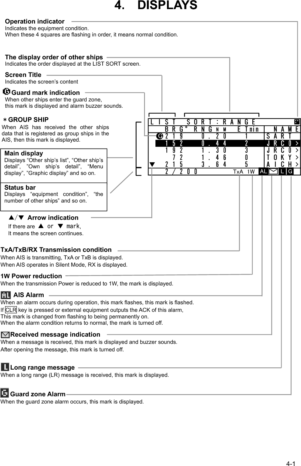
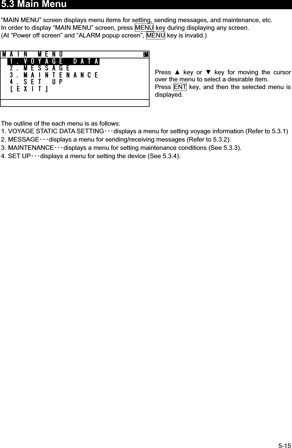
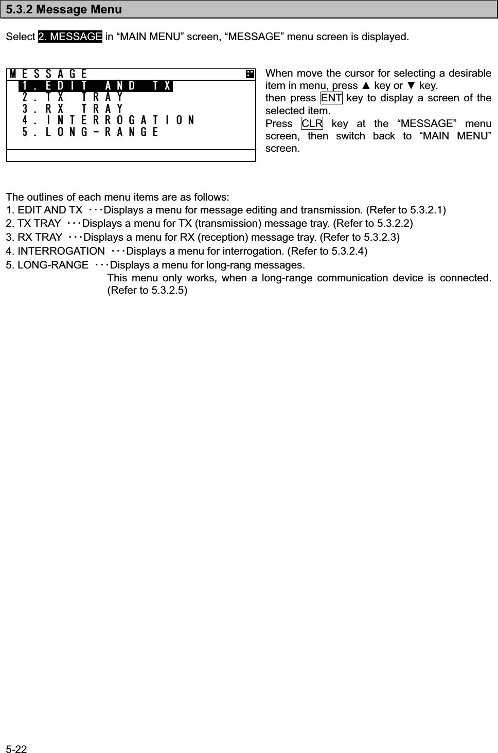
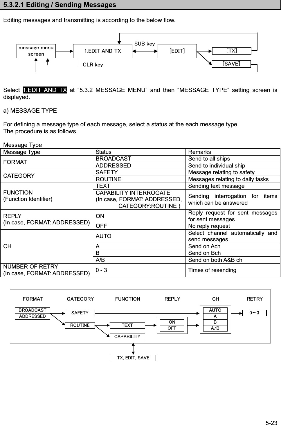
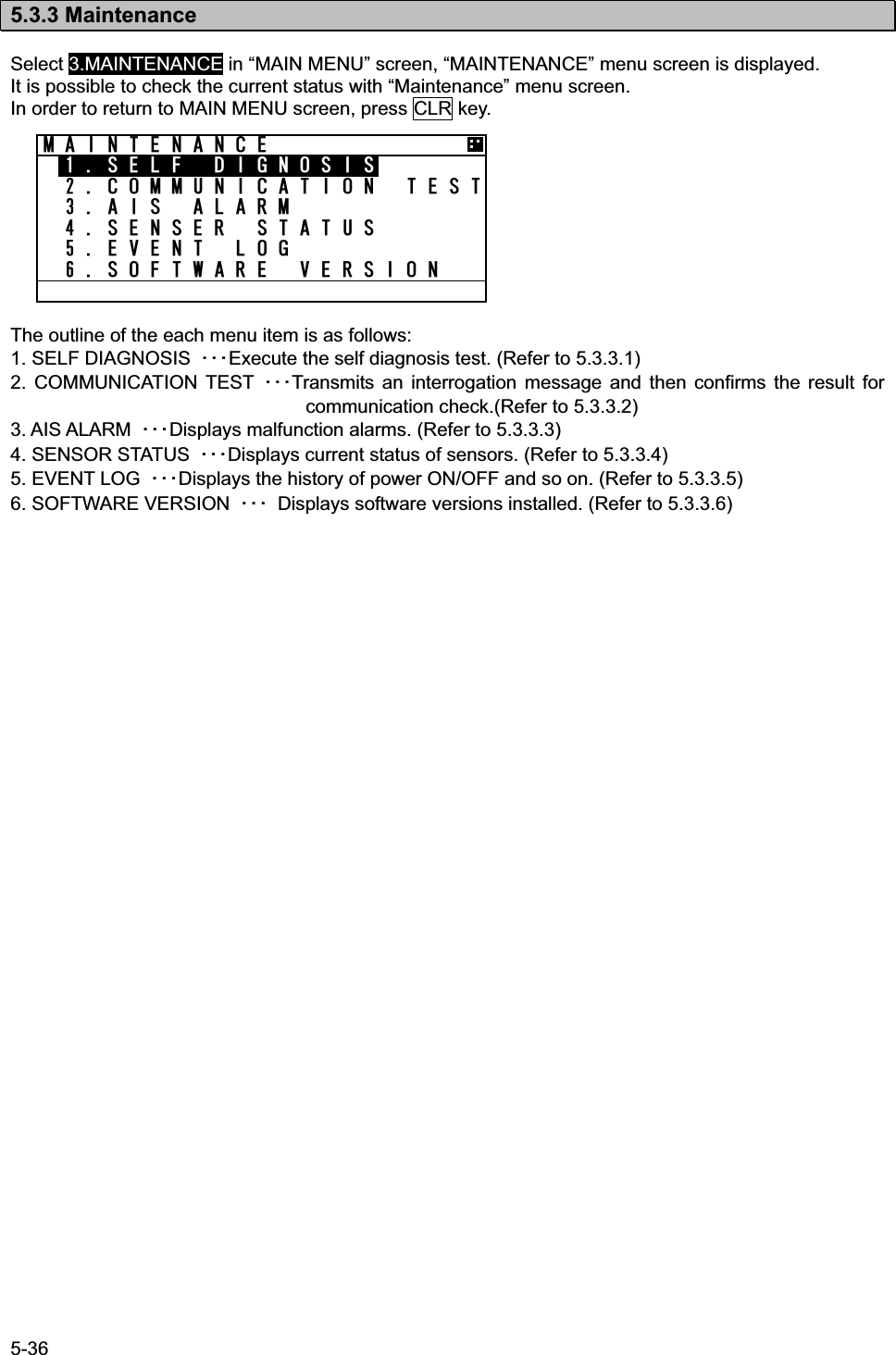
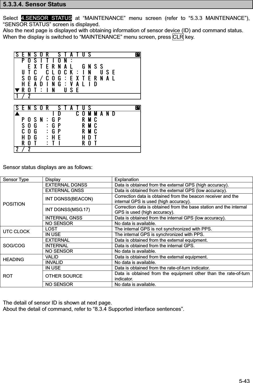
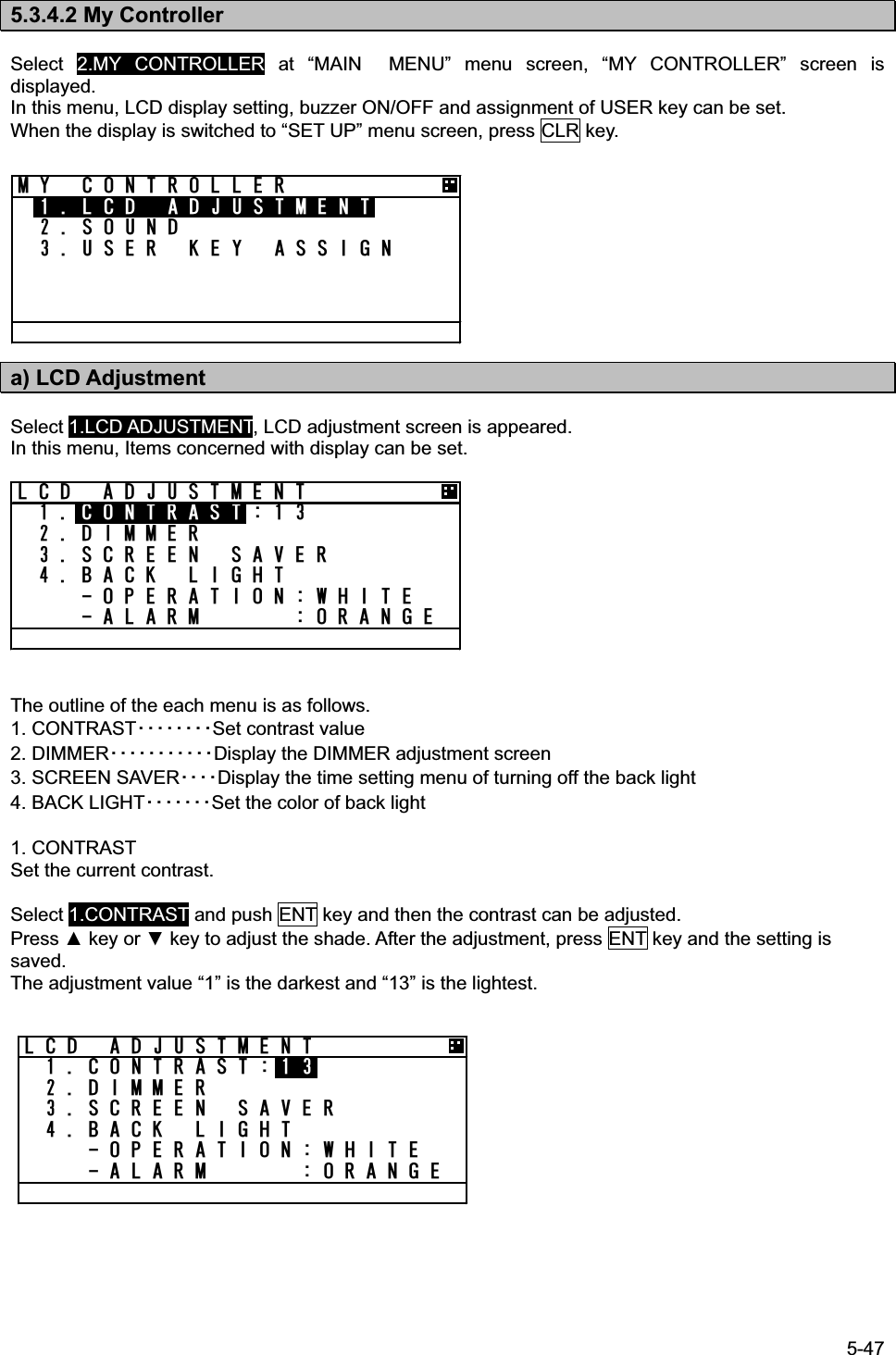
Japan Radio JHS-183 MARINE AIS CLASS A User Manual E a
Japan Radio Co Ltd. MARINE AIS CLASS A E a
UserManual.wiki
>
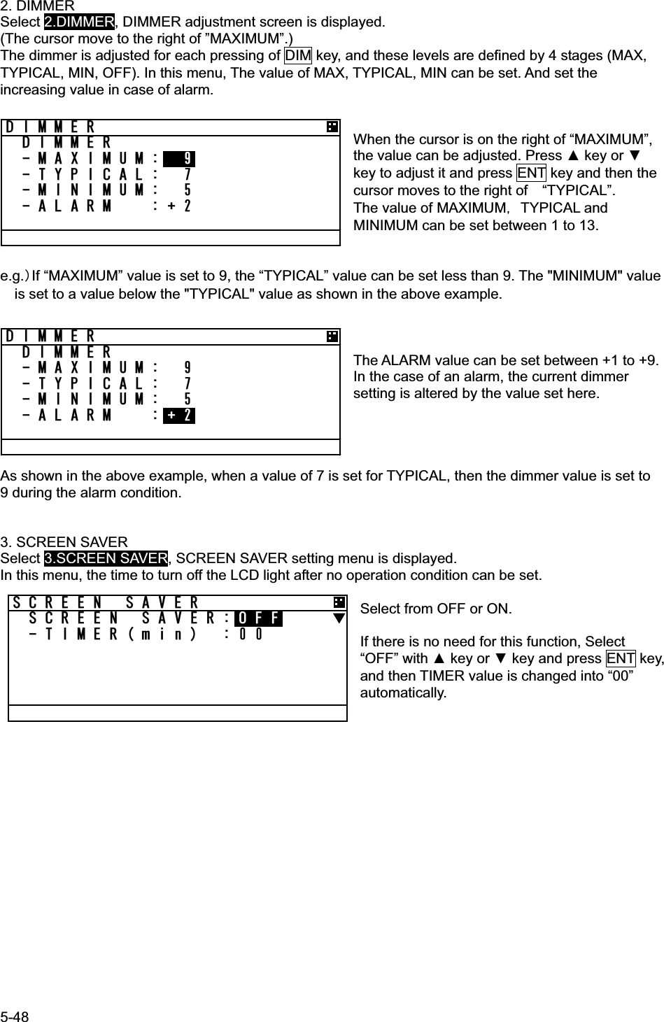
Japan Radio
>
JHS-183 User Manual
>
User Manual 1
Contents
1.
User Manual 2
2.
User Manual 1
User Manual 1
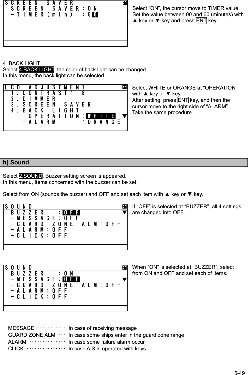
Navigation menu
Upload a User Manual
Namespaces
Wiki Guide
HTML
PDF
Info
Views
User Manual
Discussion / Help
Navigation

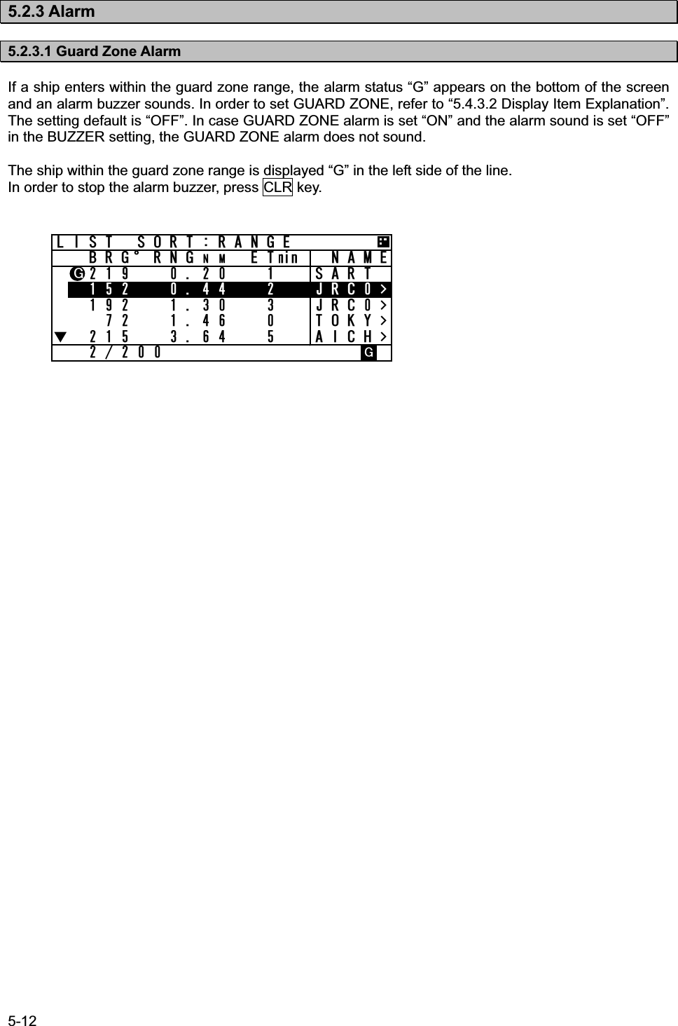
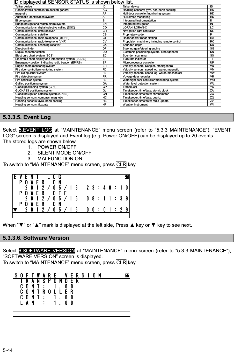
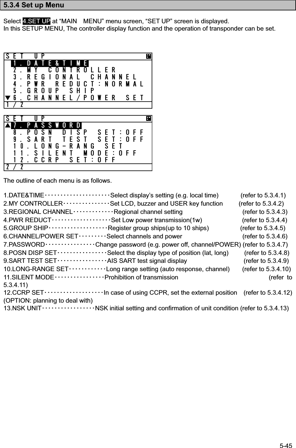
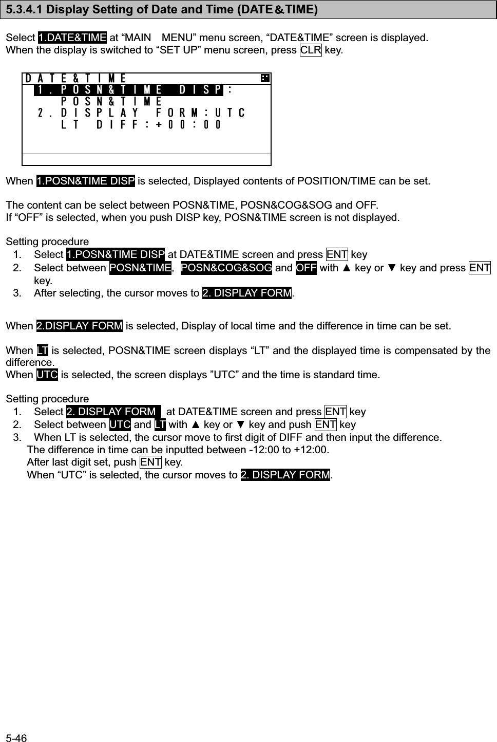
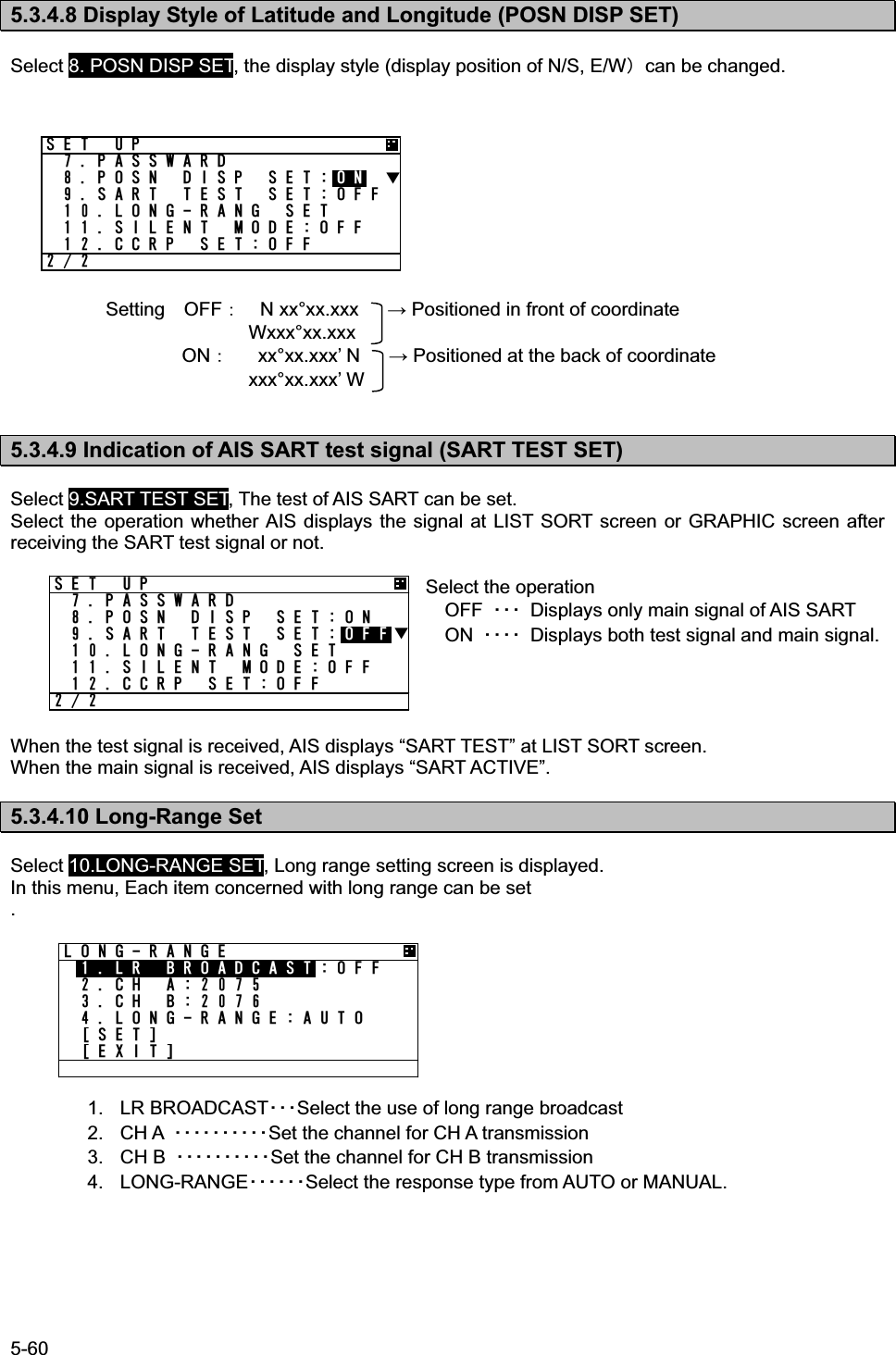
![5-1 5. OPERATION 5.1 Menu Tree POSN/Date [DISP]Own ship's TRX condition [DISP]Own ship's detail2 [DISP]Own ship's detail1 [DISP]Graphic display[SUB]1. Range2. Bearing3. Sort4. Name5 .Guard zone6. Number of ships7. Contrast [DISP] 8. Auto range set(Power ON)[ENT] [SUB] Edit and TXOther ship's detail InfoInterrogationEXIT [CLR]key + [DISP]key [DISP] [SUB] [CLR]key + [USER]key1. Bearing2. Sort3. Name4. Disp䫹䫹or [ENT] 䫹䫹or [ENT] 䫹䫹or [ENT] [MENU] 䫹 [CLR] [DISP]䫹䫹or [CLR] 䫹䫹or [CLR] 䫹䫹or [CLR][MENU]Main menu 1. Voyage static data 1. Navigational status2. Destination3. ETA [SET]4. Draught [DIST LOAD]Setting Screen from [DEST LOAD]5. Cargo/Status [EXIT]6. Persons on board2. Message 1. Edit and TX 1. Format/MMSI2. Category [EDIT]3. Function [TX] Text edit Screen(4). Reply [SAVE]5. Channel [EXIT](6). Number of retry2. TX tray 1. Sent messages [DETAIL VIEW] TX Message Screen[EDIT][DELETE][EXIT]3. RX tray1. Received safety related messages [DETAIL VIEW] RX Message Screen2. Received others messages ([REPLY])([EDIT])[DELETE][EXIT]4. Interrogation 1. MMSI [TX]2. Request [CHECK] Interrogation Screen[CLEAR][EXIT]5. Long-range Long-range message screen ([REPLY)([NOT REPLY])[EXIT]3. Maintenance 1. Self diagnosis 1. Transponder2. Controller3. Controller LAN4. Transponder log Log screen5. Controller log Log screen6. Controller LAN log Log screen2. Communication test Destination3. AIS ALARM Alarm information screen Alarm history4. Sensor status Sensor status screen5. Event log Log screen6. Software versionSoftware version - Transponder cont - Controller disp - Controller LAN (- NSK unit)4. SET UP 1. Date and time 1. POSN/Time disp2. Display form - UTC/LT - LT diff2. My Controller 1. LCD adjustment 1. Contrast2. DimmerDimmer - Maximum - Typical - Minimum - Alarm3. Screen saver4. Back Light - Operation- Alarm2. SoundBuzzer - Message - Guard zone alarm - Alarm - Click3. User key assign User key assign screen3. Regional channel setting 1. CH A: CH, TRX2. CH B: CH, TRX [CHECK]3. TX/RX mode [SAVE]4. TX power [LIST] Setting List Screen5. Zone size [CLEAR]6. Area (NE) [EXIT]7. Area (SW)8. Source4. Power reduction5. Group ship 1. Ship name,MMSI [SAVE][CLEAR][ALL CLEAR][EXIT]6. Channel/power setting 1. CH A: CH [SET]2. CH B: CH [EXIT]3. POWER7. Password 1. User level8. POSN disp setting9. AIS SART test mode setting10. Long-range setting 1. LR Broadcast 2. CH A [SET]3. CH B [EXIT]4. Long-range response11.Silent mode12.CCRP setting(13. NSK unit) 1. Heading2. Alarm3. Type4. Ratio [SET]5. Direction [EXIT]6. Output timing7. Simulator8. ERR timingOther ships listSUBSUBSUBSUBSUBSUBSUBSUBSUBSUB](https://usermanual.wiki/Japan-Radio/JHS-183.User-Manual-1/User-Guide-1846411-Page-27.png)
![5-2 .+56 51464#0)'$4)c40)0/'6OKP //5+ Ť 㪫㫏㪘 5.2 Basic Operation 5.2.1 Turning ON the power Holding down the PWR/CONT key for 1 second turns on the power, the starting screen appears about 2 seconds later, and then the Other Ships List display appears about 10 seconds later. Caution: Check the main power supply of the switchboard and a cable connection of NCM-983 AIS controller when the power cannot be turned on. During operation, Pressing MENU key displays MAIN MENU. Pressing DISP key switches the screen. Pressing OFF key displays the screen for turning off the power. When alarm buzzer is beeping, press CLR key to stop the beeping. When alarm display is displaying, press CLR key to close the display. The alarm buzzer can be disabled through the initial setting menu. (Refer to “5.3.4.2 b) Sound”.) When the Other Ships List is displayed, transmission is started after 1 minute later. While the transponder transmits normally, “Tx A (Tx B)” is displayed in the status line. (“TxA” and “TxB” are indicated alternately. If the transmission interval is 10s, the controller displays “TxA” for 10s and then “TxB” for 10s and repeats the operation.) When the saved data is different between AIS Transponder and AIS Controller, the information screen is displayed. The following items are displayed in the information screen. - VOYAGE STATIC DATA : The voyage static data mismatching. - SHIP STATIC DATA : The ship static data mismatching. - MMSI / IMO NO. : The MMSI and IMO No. mismatching. - MMSI SETTING : 000000000 : The MMSI No. is ‘000000000’ setting. - NG AIS TRANSPONDER [CONTROL UNIT] : Failure of the control unit (CDJ) in the AIS TRANSPONDER The cases when there can be a data difference is explained on the following page.](https://usermanual.wiki/Japan-Radio/JHS-183.User-Manual-1/User-Guide-1846411-Page-28.png)
![5-3 #.#4/&#6# /+5/#6%*=//5++/15*+285&?+0+6+#. 5'66+0) 4'34'56#46/#+06'0#0%'/1&'24'55 #0& *1.&=294%106?=&+/? a) The voyage static data mismatch When only voyage data is different, it is displayed as follows. When [OK] is selected, voyage static data setting screen is displayed. When [CANCEL] is selected, LIST SORT screen is displayed. Confirms the voyage data and select [ENT]. Refer to 5.3.1 VOYAGE DATA SETTING for the change of the setting and the operating method. b) Other data mismatching When the following item is displayed, press and hold PWR/CONT and DIM keys together until the power is turned off (refer to 5.2.2). - SHIP STATIC DATA - MMSI / IMO NO. - MMSI SETTING : 000000000 According to the information screen, contact our service center or agents. Example) Ship static data, MMSI/IMO No., Voyage static data mismatching Different contents are displayed. Press and hold PWR/CONT and DIM keys together in order to turn off the power. Select [CANCEL], LIST SORT screen is displayed. Select [OK], VOYAGE DATA screen is displayed. 85& 4'%10(+)&#6# /+5/#6%*=81;#)' &#6#?4'%10(+)74'!=1-?=%#0%'.?.+56 51464#0)'$4)c40)0/'6OKP 0#/' 5#46 ,4% ,4% 61-; Ť #+%* 81;#)' &#6#0#856#675'0)#)'& +0 (+5*+0)&'56+0#6+10,#2#0'6#Ť ](https://usermanual.wiki/Japan-Radio/JHS-183.User-Manual-1/User-Guide-1846411-Page-29.png)
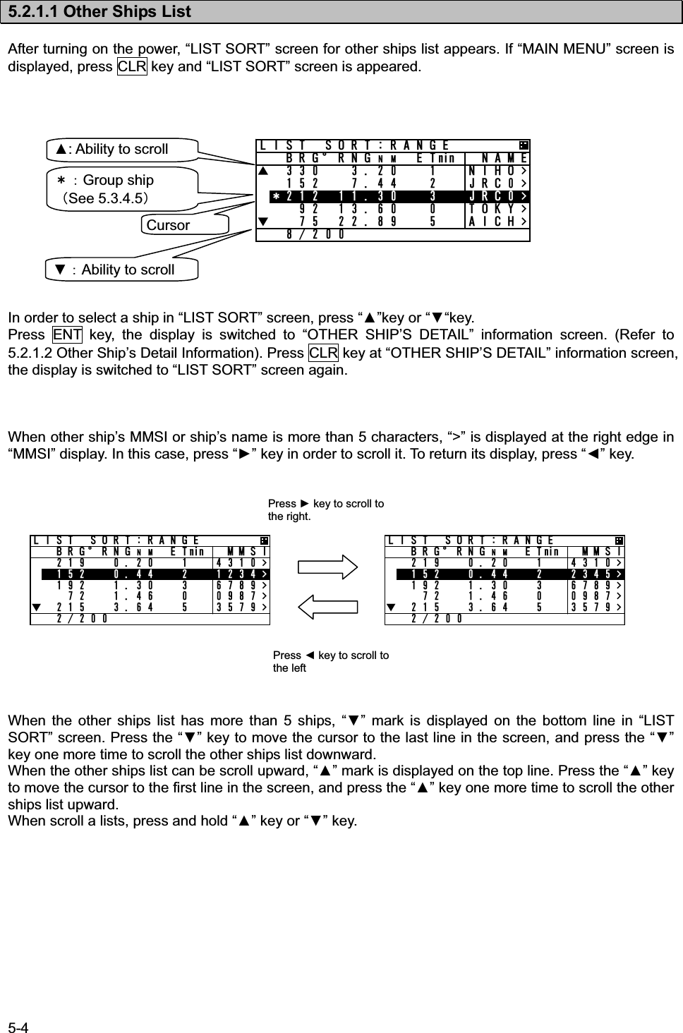
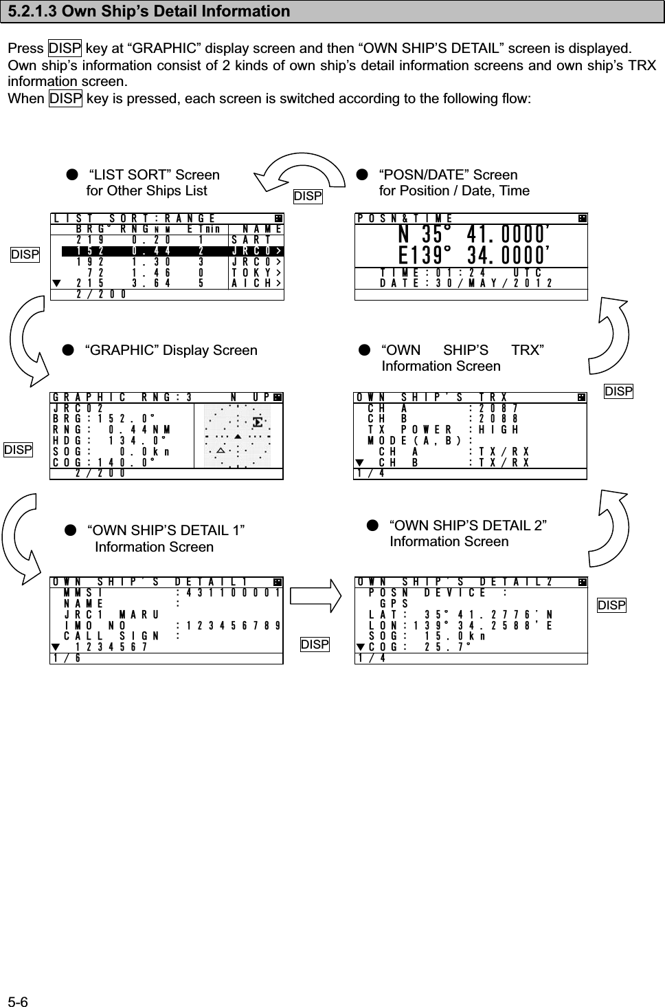
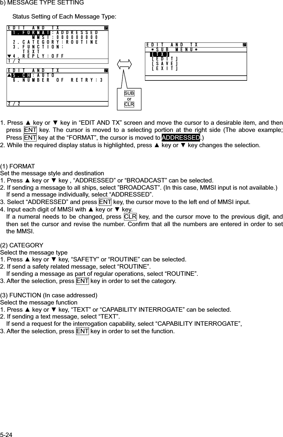
![5-5 5.2.1.2 Other Ship’s Detail Information In order to see detail information of a ship selected at “LIST SORT” screen or “GRAPHIC” display screen, Press ENT key, and then the screen is switched to “OTHER SHIP’S DETAIL” information screen. When the display is changed the next page / the previous page, press “”key or ““key. Press SUB key in order to display the Sub menu, and then the cursor can be moved with “”key or ““key. When the display is switched to “LIST SORT” screen for other ships list, select [EXIT], and then press ENT key. When the display is switched to “EDIT AND TX” screen for sending message, select [EDIT AND TX], and then press ENT key. (refer to “5.3.2.1 Editing / Sending Messages.”) When the display is switched to “INTERROGATION” screen for interrogating to other ship, select [INTERROGATION], and then press ENT key. (refer to “5.3.2.4 Interrogation.”) In order to switch to “LIST SORT” screen for other ships list (or “GRAPHIC” display screen), press CLR key. ً or ٕ SUB or CLR 16*'4 5*+25 &'6#+.57$ /'07='&+6 #0& 6:?=+06'441)#6+10?=':+6?The contents of screen 8/9, 9/9 are shown below. CARGO/SATUS: Cargo type MF ID: Manufacture code (factory code) MODEL CODE: Model information (e.g. AIS JHS-183, MF ID:JRCޔMODEL CODE:3㧕NO: Serial number of the other’s AIS CPA: Closest point of approach TCPA: Time to closest point to approach BEARING: The direction of the ship RANGE: The range from the ship.16*'4 5*+25 &'6#+.//5+ 0#/' ,4% /#47+/1 01 %#.. 5+)0 Ť16*'4 5*+25 &'6#+.Ţ2150 &'8+%' )25.#6 c0.10c'51) MPŤ%1) c16*'4 5*+25 &'6#+.Ţ*&) c416 cOKP2150 37#.+6;2150 /2#.19 4#+/01 75'Ť6+/' 56#/2 16*'4 5*+25 &'6#+.Ţ5;0% 56#6' 76% &+4'%64%8 56#6+105Ť16*'4 5*+25 &'6#+.Ţ0#8 56#675 70&'4 9#; 75+0) '0)+0'&'56+0#6+10 ,#2#0Ť16*'4 5*+25 &'6#+.Ţ'6#/&*/&'%&4#7)*6 O.'0)6* Ť/16*'4 5*+25 &'6#+.Ţ$'#/ /6;2' 1( 5*+2%#4)1 5*+25Ť16*'4 5*+25 &'6#+.Ţ%#4)156#675 #.. 5*+25 1( 6*+5 6;2'%.#55%.#55 #/( +&Ť/1&'. %1&'16*'4 5*+25 &'6#+.Ţ01 %2# 0/6%2# OKP$'#4+0) c4#0)' 0/](https://usermanual.wiki/Japan-Radio/JHS-183.User-Manual-1/User-Guide-1846411-Page-31.png)
![5-10 5.2.1.4 Display Setup of Other Ships List In order to change the display setting of other ship list, press SUB key at “LIST SORT” screen for other ships list and switch to SUB screen. When the screen is switched from the SUB menu screen to “LIST SORT” screen, press CLR key or select [EXIT], and then press ENT key. At SUB menu screen, Other ship’s bearing basis, sorting of range, TCPA or own group priority order, and ship’ s name indication in “LIST SORT” screen (upper left figure) can be set. Select item at the SUB screen and press ENT key, then select a desirable indication and press ENT key again. 1. BEARING: HEAD UP : Other ship’s bearing value is displayed on the basis of own ship’s bearing. NORTH UP : Other ship’s bearing value is displayed with the north base. 2. SORT : RANGE : Other ships are displayed in the order of small range from own ship. TCPA : Other ships are displayed in the order of small TCPA with own ship. GROUP : Other ships are displayed with the priority for own group ships. 3. NAME : SHIP NAME : When receiving static information, the ship’s NAME is displayed. MMSI : Ship’s MMSI is displayed. 4. DISP : NORMAL : “LIST SORT” screen is displayed with BRG, RNG, ET and NAME. TYPE 1 : “LIST SORT” screen is displayed with BRG, RNG, and NAME. TYPE 2 : “LIST SORT” screen is displayed with BRG, and NAME. “ETmin” means the “elapsed time” from the last data received, After 7 minutes elapsed, the ship is erased from the other ship’s list. Select [SET] and then press ENT key to determine. “LIST SORT” screen for other ships list is displayed with the setting. SUB or CLR .+56 51464#0)'$4)c40)0/'6OKP 0#/' 5#46 ,4% ,4% 61-; Ť #+%* .+56 &+525'657$ /'07$'#4+0)0146*7251464#0)'0#/'5*+20#/'&+52014/#.Ť=5'6?.+56 &+525'657$ /'07Ţ=':+6?ً or ٕ](https://usermanual.wiki/Japan-Radio/JHS-183.User-Manual-1/User-Guide-1846411-Page-36.png)
![5-11 5.2.1.5 Graphic Display In order to switch from “LIST SORT” screen for other ships list to “GRAPHIC” display screen, press DISP key. (Refer to 5.2.1.3 for DISP key operation) (Refer to 5.4 Graphic Display Function) 5.2.2 Turning OFF the Power CAUTION: The PASSWORD must be entered to turn off the power. The password preset at shipment is “0000”. The administrator must manage PASSWORD. When turn off the power, press and hold PWR/CONT key and OFF key together for 1 second and then “PASSWORD” input screen is displayed. Enter 4 digits of password, select [ENT] and press ENT key. Password is composed of alphanumeric “A㨪Z” and “0㨪9”. (Refer to “5.2.4 Character Pad Window Display and Input Method” to input the password.) After the correct password is inputted, the power is turned off. Caution:If the power is turned off by main power supply, the setup contents or received messages may not be saved. .+56 51464#0)'$4)c40)0/'6OKP 0#/' 5#46 ,4% ,4% 61-; Ť #+%* 219'4 1((2#55914&#$%&'()*+,-./0123456789:;< =᳖?A!"@ ='06?=':+6?DISP)4#2*+% 40) 0 72,4%$4)c40) 0/*&) c51) MP%1)c](https://usermanual.wiki/Japan-Radio/JHS-183.User-Manual-1/User-Guide-1846411-Page-37.png)
![5-13 5.2.4 Character Pad Window Display and Input Method a) Inputting characters When character input is needed, the character pad window is displayed. When character input operation starts, the cursor is on “A” in the character pad window. Pressing ““ in the arrow key, the cursor is moved to like that “B”, “C”, “D”, ----. Set the cursor on a desirable input character, and then press ENT key. The number of characters is displayed in the bottom. Text Setting Window Character Pad Window - In order to move the cursor to the other window (Ԙwindow ÅÆԙwindow), press SUB key. - When clear all inputting characters, select [AC] and then the cursor is moved to the top in the character input line. - When clear the current inputting character, select [C] and then the cursor is moved to the one-character front. b) Inserting a character The procedure which inserts a character in the text is followings: 1. Press SUB key in order to move the cursor in Text window. 2. Then the cursor in Text Window can be moved with the arrow key. Therefore move the cursor to insert position in the text. 3. Press SUB key in order to move the cursor in Character pad window. Select a desirable insert character and press ENT key. Therefore the selected character is inserted at the cursor position in Text window. 4. After inserted characters, if you wish to move the cursor to the end of the text, press SUB key to move the cursor in Text window, and then move the cursor to the end of the text. 5. Additional characters can be inputted at the end of the text. 1 2&'56+0#6+1061-;1#$%&'()*+,-./0123456789:;< =᳖?A!"@ =%?=#%?=1-?=':+6?12](https://usermanual.wiki/Japan-Radio/JHS-183.User-Manual-1/User-Guide-1846411-Page-39.png)
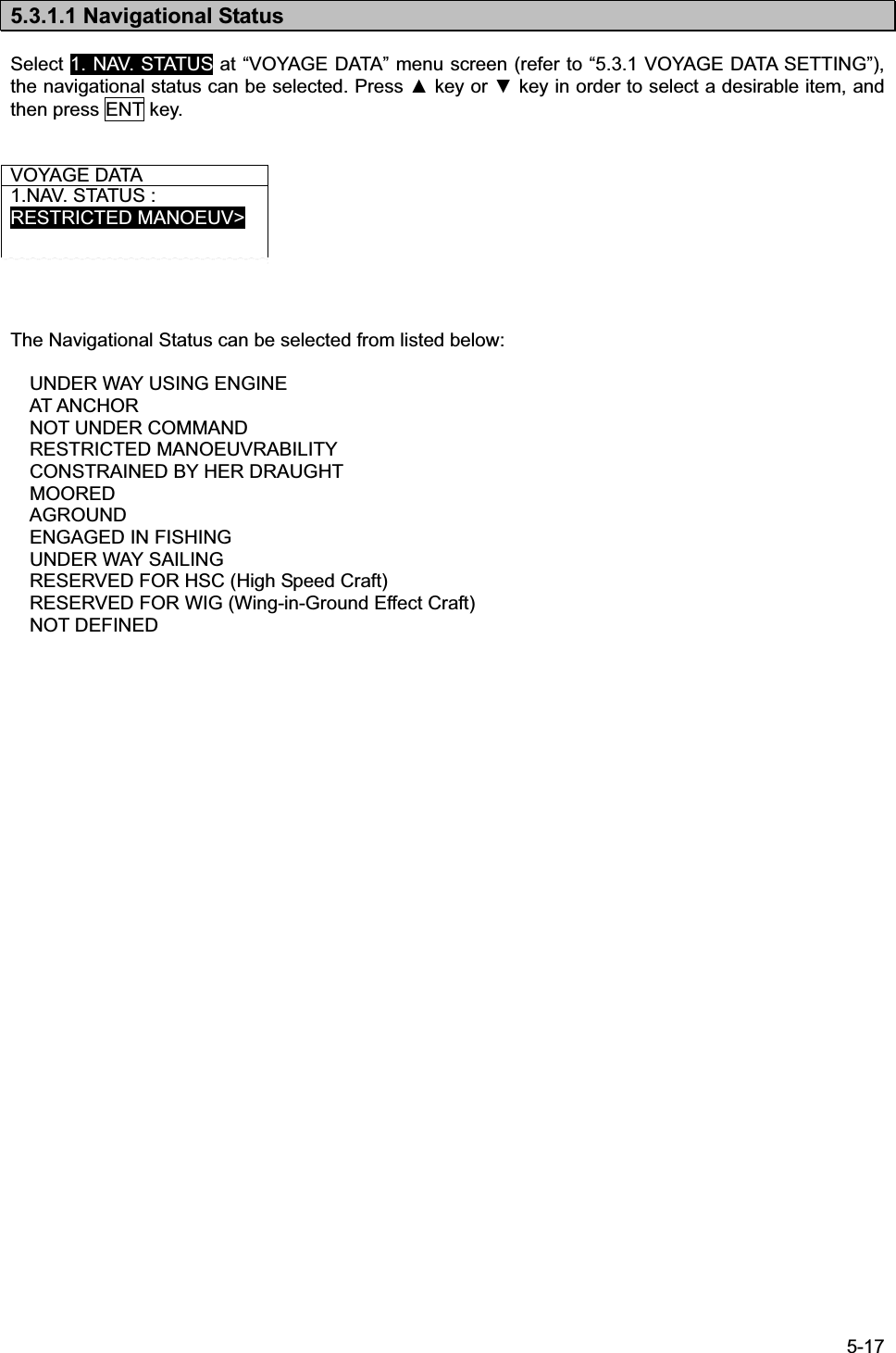
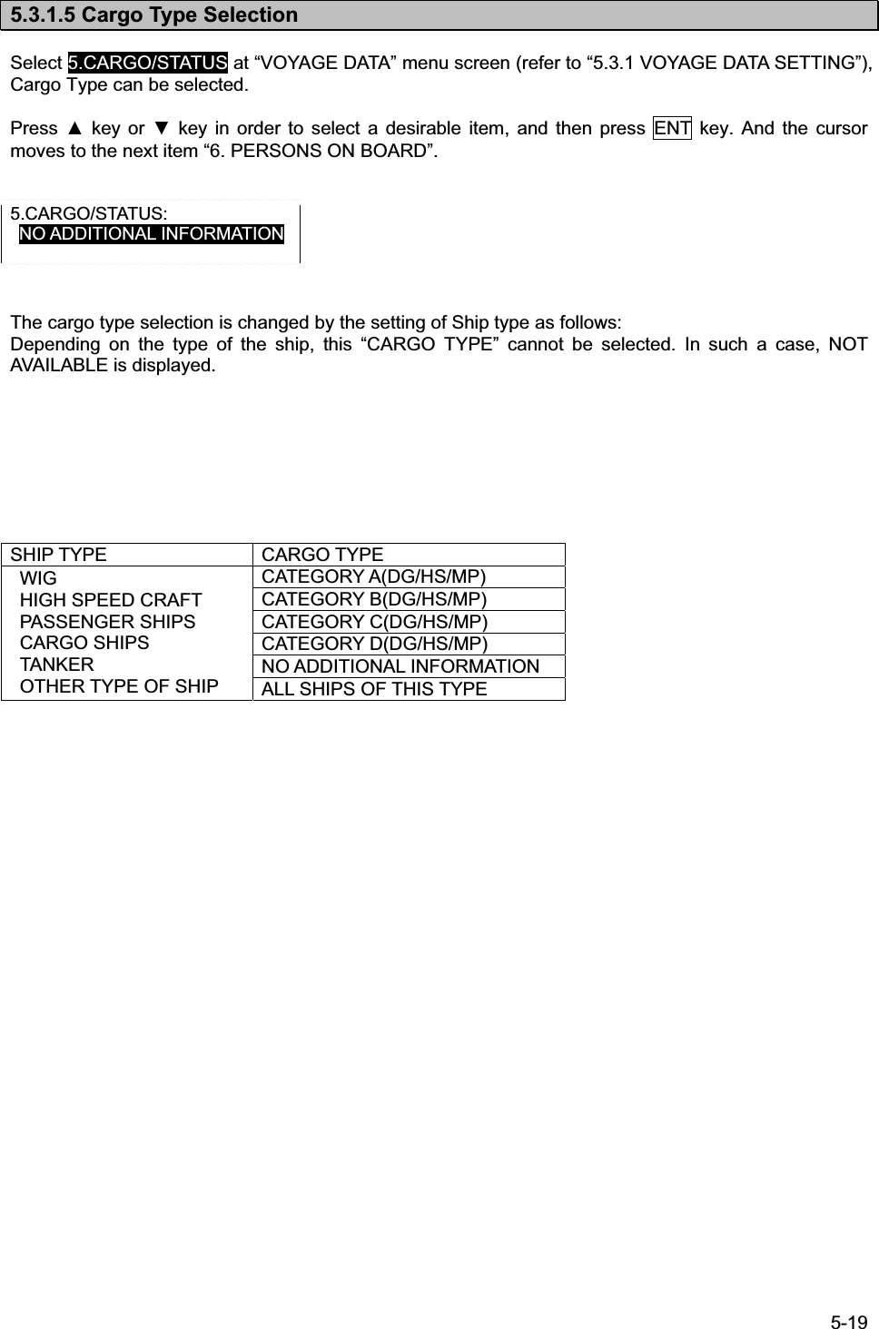
![5-16 5.3.1 Voyage data setting Select 1. VOYAGE STATIC DATA in “5.3 MAIN MENU” screen, “VOYAGE DATA” menu screen for setting is displayed. Press key or key to select a desirable setting item and press ENT key, then selecting item and inputting data are available. To switch to “VOYAGE DATA” menu screen, press CLR key during selecting item or inputting data. To switch to “MAIN MENU” screen, press CLR key at “VOYAGE DATA” menu screen. When the SUB menu screen is displayed, press SUB or CLR key and switch to “VOYAGE DATA” menu screen. Select [SET] at the sub menu screen, the setting is saved. If [EXIT] is selected at the sub menu screen, the screen is returned to “MAIN MENU”. In order to select a destination from past inputted destinations, Select [DEST LOAD] at the sub menu. (Refer to “5.3.1.7 Re-load destination”.) The outline of the each menu is as follows: 1. NAV. STATUS㨯㨯㨯select navigational status. (Refer to 5.3.1.1) 2. DESTINATION㨯㨯㨯input the destination. (Refer to 5.3.1.2) 3. ETA㨯㨯㨯input ETA(expected time for arrival). (Refer to 5.3.1.3) 4. DRAUGHT㨯㨯㨯input draught value.( Refer to 5.3.1.4) 5. CARGO/STATUS㨯㨯㨯select cargo/status.( Refer to 5.3.1.5) 6. PERSONS ON-BOARD㨯㨯㨯input the number of persons on-board.( Refer to 5.3.1.6) Caution: In order to save the setting, select [SET] at the SUB menu. If you switch to any other screen without selecting [SET], the setting is not saved. ً or ٕ SUB or CLR 81;#)' &#6#0#856#675'0)#)'& +0 (+5*+0)&'56+0#6+10,#2#0'6#Ť 81;#)' &#6#Ţ&4#7)*6/%#4)156#675#.. 5*+25 1( 6*+ 2'45105 10 $1#4&81;#)' &#6#57$ /'07=5'6?=&'56 .1#&?=':+6?](https://usermanual.wiki/Japan-Radio/JHS-183.User-Manual-1/User-Guide-1846411-Page-42.png)
![5-18 5.3.1.2 Destination Input Select 2.DESTINATION at “VOYAGE DATA” menu screen (refer to “5.3.1 VOYAGE DATA SETTING”), the name of the destination can be inputted. The name can be inputted with using the Character Pad window at the bottom of the screen. Refer to “5.2.4 Character Pad Window Display And Input Method” in order to input characters. Operation at the Destination Name Input screen is as follows: Up to 20 characters can be entered for naming destination. Select [EXIT] on the bottom right of the Character Pad window, discard a current inputting characters and the cursor is returned to 2.DESTINATION. Select [OK], Name of destination has been set. and the cursor moves to the next item “3.ETA”. Select [AC], all characters inputted are cleared, and the cursor moves to the top of the line. Select [C], the current character is cleared, and the cursor moves to the one- character front. 5.3.1.3 Estimated Time of Arrival (ETA) Input Select 3. ETA at “VOYAGE DATA” menu screen (refer to “5.3.1 VOYAGE DATA SETTING”), ETA (Expected Time of Arrival) can be inputted. (Refer to “5.2.5 Numerical Input” for numerical input procedure.) ETA input procedure is as follows: Input numerals for ETA on UTC in the order of Month-Day-Hour-Minute with key or key. ‘/’ will be inserted automatically. After inputting the last “Minute”, the cursor moves to the next item “4. DRAUGHT” (Draught Value Input). 5.3.1.4 Draught Value Input Select 4. DRAUGHT at “VOYAGE DATA” menu screen (refer to “5.3.1 VOYAGE DATA SETTING”), the draught value can be inputted. Input a value according to the procedure of ”5.2.5 Numerical Input”. The input range of draught is between 0 and 99.9 m. When the inputted value is greater than 25.5 m, “25.5M OR GREATER” is displayed. After pressing ENT key and the draught value has been set. Then the cursor moves to the next item “5.CARGO/STATUS”. 3.ETA : 12/31 23:31 4.DRAUGHT : 25.4M &'56+0#6+1061-;1#$%&'()*+,-./0123456789:;< =᳖?A!"@ =%?=#%?=1-?=':+6?](https://usermanual.wiki/Japan-Radio/JHS-183.User-Manual-1/User-Guide-1846411-Page-44.png)
![5-20 5.3.1.6 Persons on Board Input Select 6. PERSONS ON BOARD at “VOYAGE DATA” menu screen (refer to “5.3.1 VOYAGE DATA SETTING”), the number of persons on board can be inputted. Input a value with key or key according to the procedure of ”5.2.5 Numerical Input”. The input range of PERSONS is between 0 and 9999. When the inputted number is more than “8191”, “8191 OR MORE” is displayed. 6. PERSONS ON BOARD : 8191 After pressing ENT key at the last digit, the inputted PERSONS has been set. And the cursor returns to “6. PERSONS ON BOARD”. Caution: In order to save the setting, select [SET] in the SUB menu screen. If [SET] in the SUB menu is not selected, the setting is not saved.](https://usermanual.wiki/Japan-Radio/JHS-183.User-Manual-1/User-Guide-1846411-Page-46.png)
![5-21 5.3.1.7 Re-load Destination from history Data Select [DEST LOAD] in the sub menu in “5.3.1 VOYAGE DATA SETTING”, Destinations list (current destination and 4 destinations in the past) is displayed. Select the destination from the list and press ENT key, then the screen is switched to “VOYAGE DATA” menu screen and the selected one is displayed at the 2.DESTINATION. If CLR key is pressed at “DEST LOAD” screen, the re-load operation is canceled and switch back to “VOYAGE DATA” screen. If a past destination is selected from the DEST LOAD screen, the destination is displayed as the newest at the DEST LOAD screen. e.g.) If TOKYO is selected on the setting procedure above, the “DEST. LOAD” screen is changed as shown below. 㧔Example㧕 YOKOHAMA TOKYO ABCDEFGHIJKLMNOPQRST YOKOHAMA TOKYO ABCDEFGHIJKLMNOPQRST AFRICA AFRICA 01234567890123456789 01234567890123456789 Select [DEST LOAD]CLR key Select a destination, and then press ENT key. 81;#)' &#6#57$ /'07=5'6?=&'56 .1#&?=':+6?&'56 .1#&;1-1*#/##$%&'()*+,-./012345661-;1#(4+%#81;#)' &#6#0#856#675'0)#)'& +0 (+5*+0&'56+0#6+1061-;1'6#Ť Ť](https://usermanual.wiki/Japan-Radio/JHS-183.User-Manual-1/User-Guide-1846411-Page-47.png)
![5-26 6':6 '&+6 5%4''0*19 #4' ;17!#$%&'()*+,-./0123456789:;< =᳖?A!"@ =%?=#%?=1-?=':+6?'&+6 #0& 6:57$ /'07='&+6?=6:?=5#8'?=':+6? c) TEXT EDIT SCREEN In order to transmit a text message, press SUB key at “EDIT AND TX” screen and SUB menu screen is displayed and then select [EDIT]. Refer to the procedure of “5.2.4 Character Pad window Display and Input Method” to input character.. TEXT EDIT screen is composed of 2screens. 1. After editing the text, move the cursor to [OK] in Character Pad window and press ENT key. The edit has been set and the cursor is jumps back to the SUB menu screen. 2. If cancel the editing text, move the cursor to [EXIT] and press ENT key. The text has been canceled and the cursor is returns to the SUB menu screen. - Maximum number of characters to send a message FORMAT CATEGORY MAXIMUM CHARACTERS SAFETY 156 ADDRESSED ROUTINE 151 SAFETY 161 BROADCAST ROUTINE 156 21 3](https://usermanual.wiki/Japan-Radio/JHS-183.User-Manual-1/User-Guide-1846411-Page-52.png)
![5-27 d) Transmitting and Saving If “FUNCTION” in Message Type (refer to “a) MESSAGE”, and “b) MESSAGE TYPE SETTING”) is “TEXT”, operate transmitting or saving a message according to the following procedure: - After editing, select “SAVE” in SUB menu. Then the message is saved in TX TRAY. - If [EXIT] is selected, return to “EDIT AND TX” screen for message type setting. Select [TX] in “EDIT AND TX” sub screen and press ENT key. A confirmation message is appeared. If select [OK], the message is transmitted. After its acknowledgement is received, “RESULT: ACK OK” is displayed. Press [OK] and then return to “EDIT AND TX” screen. In case of ADDRESSED In case of BROADCAST e) SETTING TIMES OF RETRY When AIS transmits the individual message (FORMAT: ADDRESSED), the acknowledgement of receiving the message is replied from the destination. If the acknowledgement could not be received after transmitting, the transmission is retried. The Numbers of retry can be set between 0 and 3 times. However, when the numbers of retry is set to 0~2 times (except 3 times), its numbers is changed to 3 times as the default after 8 minutes. 6. NUMBER OF RETRY: 3 6. NUMBER OF RETRY: 3 6. NUMBER OF RETRY: 1 Set to 0~2 with key or key Change to “3” after 8 minutes '&+6 #0& 6:57$ /'07='&+6?=6:?=5#8'?=':+6?'&+6 #0& 6:56#46 64#05/+66*+5/'55#)'!=1-?=%#0%'.?'&+6 #0& 6:019 64#05/+66+0) '&+6 #0& 6:4'57.6#%- 1-=1-?'&+6 #0& 6:64#05/+61-=1-?](https://usermanual.wiki/Japan-Radio/JHS-183.User-Manual-1/User-Guide-1846411-Page-53.png)
![5-28 5.3.2.2 TX Tray (Viewing Transmitted Messages) Select 2. TX TRAY at “MESSAGE” menu screen (refer to “5.3.2 MESSAGE MENU”),“TX TRAY” screen is displayed. Transmitted and edited messages can be saved up to 10 massages in the transmitted message list. The listed messages can be edited and/or can be transmitted again. Transmitted Message List Press ENT key Press CLR key Press SUB key Press SUB key Select [EXIT] Press SUB key Press SUB key Select [EXIT] Select [EDIT] Select [DETAIL VIEW] Sub Menu Screen TX VIEW screen EDIT AND TX screen Detail Information Screen 6: 64#;$41#&%#56,4%*#-7;17/#47$41#&%#56$41#&%#56Ť*#-7;17/#476':68+'9 5%4''0*19#4';17!6: 64#;57$ /'07=&'6#+. 8+'9?='&+6?=&'.'6'?=':+6?*#-7;17/#47 %#6')14;4176+0'4'2.;1(((70%6+106':6%*#761 4'57.61-$41#&%#56 $41#&%#56%#6')14;5#('6;4'2.;1(((70%6+106':6%*#761 64#05/+61-'&+6 #0& 6:(14/#6#&&4'55'&//5+%#6')14;4176+0'(70%6+106':6Ť4'2.;1((Press CLR key If STATIC DATA is not received at the message transmission, it is saved by “MMSI” in the TRAY After received STATIC DATA, it is saved by “NAME” in the TRAY.](https://usermanual.wiki/Japan-Radio/JHS-183.User-Manual-1/User-Guide-1846411-Page-54.png)
![5-29 Press key or key in order to select a desirable message in the display list in “TX TRAY” screen, and then press ENT key. The selected message is displayed in ”TEXT VIEW SCREEN”. “㧖” mark in the front of a message number indicates not transmitted message. In order to display SUB menu screen, press SUB key at the list screen or text view screen. Select [DETAIL VIEW] and press ENT key, detail information screen is displayed with the following information: 1. Transmitted or edited date and time with UTC. 2. FORMAT: 9 digits MMSI for “ADDRESSED” “BROADCAST” as BROADCAST. 3. Other items (CATEGORY, FUNCTION, REPLY, CH) of message type: Refer to the above selected TX message detail information screen. 4. ACK (Acknowledgement): (1) Set “REPLY ON” at “ADDRESSED”, ACK display is as follows: “ACK: OK” is displayed at received ACK. “ACK: NG” is displayed at not received ACK. (2) Set “BROADCAST”, its display is as follows: “TRANSMIT OK” is displayed at succeeded transmission. “TRANSMIT NG” is displayed at Failed Transmission. When return to SUB menu screen, press CLR key at TX message detail information screen. In order to edit newly a message, select [EDIT] at the selected message’s SUB menu screen, and then the screen is switched to “EDIT AND TX” screen for message type setting. In order to delete the selected message, select [DELETE] at the selected message’s SUB menu screen, and then the message is deleted.](https://usermanual.wiki/Japan-Radio/JHS-183.User-Manual-1/User-Guide-1846411-Page-55.png)
![5-30 5.3.2.3 RX Tray (Viewing Received Messages) Select 3. RX TRAY at “MESSAGE” menu screen (refer to “5.3.2 MESSAGE MENU”), “RX TRAY” screen is displayed. In the RX TRAY, safety related messages can be saved up to 20, others messages can be saved up to 10. Confirmation of contents and reply are performed by selecting a message in the TRAY. When messages are received, receiving alarm sounds normally. If the message buzzer is set “OFF” in the BUZZER setting, receiving alarm does not sound. (“Message received popup” is appeared.) RX TRAY” Screen Press ENT key Press CLR keyPress SUB key Press SUB key Select [EXIT] Press SUB keyPress SUB keySelect [EXIT] Select [EDIT] Sub Menu Screen Select [DETAIL VIEW]EDIT AND TX Screen Detail Information screen TEXT VIEW screen 16*'45 /'55#)'5 64#; $41#&%#56 4 ,4%4 ,4% $41#&%#56$41#&%#56Ť*#-7;17/#476':68+'9 5%4''0*19#4';17!16*'45 /'55#)'5 64#;57$ /'07=&'6#+. 8+'9?='&+6?=&'.'6'?=':+6?Press CLR key'&+6 #0&6:(14/#6#&&4'55'&//5+%#6')14;4176+0'(70%6+106':6Ť4'2.;1((If STATIC DATA is not received at the message receiving, it is saved by “MMSI” in the TRAY After received STATIC DATA, it is saved by “NAME” in the TRAY. $41#&%#56 $41#&%#56%#6')14;4176+0'4'2.;1(((70%6+106':6%*#](https://usermanual.wiki/Japan-Radio/JHS-183.User-Manual-1/User-Guide-1846411-Page-56.png)
![5-31 Press key or key in order to select a desirable message in the list “1. SAFETY MESSAGES” tray and “2. OTHERS MESSAGES” tray in “RX TRAY” screen, and then press ENT key. The selected message is displayed in TEXT VIEW screen. “㧖” mark in the front of a message number indicates an unread message. “R” mark in the front of a message number indicates that it is a received message with reply and a reply is not carried out at that time. In order to display SUB menu screen, press SUB key at the list screen or text view screen. Select [DETAIL VIEW] and press ENT key, detail information screen is displayed with the following information: 1. Received or edited date and time with UTC 2. FORMAT: 9 digits MMSI for ADDRESSED “BROADCAST” as BROADCAST 3. Other items (CATEGORY, FUNCTION, REPLY, CH) of message type: Refer to the above selected RX message detail information screen. In order to return to SUB menu screen, press CLR key at TX message detail information screen. In order to edit newly a message such as replay, select [EDIT] at the selected message’s sub menu screen, and then the screen is switched to “EDIT AND TX” screen for message type setting. However the reply cannot be performed with BROADCAST, since the [EDIT] selection is reply for a receiving “ADDRESSED” message. In order to delete the selected message, select [DELETE] at the selected message’s sub menu screen and then the message is deleted. A received message with Reply: The message type of the received message is the following setting. 1. Received Message Type = FORMAT: ADDRESSED, CATEGORY: ROUTINE, FUNCTION: TEXT, REPLY: ON 2. Received Message Type = FUNCTION: CAPABILITY INTERROGATION In case of transmitting by CAPABILITY INTERROGATE, the contents of FI number in the received message is shown below. 0)TEXT TELEGRAM 1)APPLICATION ACK 2)INTERROGATION FM 3)CAPABILITY INTERROGATION 4)CAPABILITY INTERROGATION REPLY](https://usermanual.wiki/Japan-Radio/JHS-183.User-Manual-1/User-Guide-1846411-Page-57.png)
![5-32 5.3.2.4 Interrogation Select 4. INTERROGATION at “MESSAGE” menu screen (refer to “5.3.2 MESSAGE MENU”), “INTEROGATION” screen is displayed. An interrogation message can request information with an addressed “MMSI” specified. a) INTERROGATION SETTINGS Set an address and its interrogation request item in “INTERROGATION” screen. Its interrogation request can be performed with the times in “b) INTERROGATION REQUEST ITEM LIST” below. Select 1. MMSII, and then the cursor move to the left end of the digit at “1. MMSI” right side. Input the each digit of MMSI with key or key. After inputted all 9 digits, press ENT key and then the MMSI has been set and the cursor is moves to “2. REQUEST:”. Select 2. REUESTI, Press key or key to move the cursor to a desirable item, and then press ENT key and the selected item has been set. (The interrogation request item are shown in “b) INTERROGATION REQUEST ITEM LIST” below.) b) INTERROGATION REQUEST ITEM LIST The following table is the list for possible interrogation request items. (“CLASS” in the list indicates a kind of AIS on board.) (: selective) Interrogation Item Request Note POSN REPORT(A) Class A shipborne AIS Position Report STATIC/VOYAGE(A) Class A shipborne AIS ship static and voyage data SAR AIRCRAFT POS. REPORT Search and rescue aircraft AIS position report UTC AND DATE Date and time data with UTC POSN REPORT(B) Class B shipborne AIS Position Report STATIC/VOYAGE(B) Class B shipborne AIS ship static and voyage data AIDS-TO-NAVIGATION REPORT Aids to navigation AIS report BASE STATION REPORT Base station AIS report STATIC DATA REPORT Static data report Caution:Check the class of the destination station at “OTHER SHIP’S DETAIL” screen in “5.2.1.2Other Ship’s Detail Information”. If mismatch the class, the ship does not receive the interrogation message. SUB key SUB / CLR key Select [EXIT]Responded Message Screen INTERROGATION Screen +06'441)#6+10//5+ 4'37'5676%#0&&#6' 4'57.6+06'441)#6+1057$ /'07=6:?=%*'%-?=%.'#4?=':+6?+06'441)#6+104'57.6#%- 1-=1-?+06'441)#6+10019 64#05/+66+0) Select [TX]](https://usermanual.wiki/Japan-Radio/JHS-183.User-Manual-1/User-Guide-1846411-Page-58.png)
![5-33 c) SUB menu screen Select an item in SUB menu screen, the each item operation is as follows: [TX] 㨯㨯㨯㨯㨯㨯㨯㨯㨯㨯㨯㨯㨯㨯㨯Transmit the interrogation message [CHECK] 㨯㨯㨯㨯㨯㨯㨯㨯㨯㨯㨯The responded message for the interrogation message is displayed. [CLEAR] 㨯㨯㨯㨯㨯㨯㨯㨯㨯㨯㨯㨯The cursor move to “1. MSSI”. [EXIT] 㨯㨯㨯㨯㨯㨯㨯㨯㨯㨯㨯㨯㨯㨯Return to “INTERROGATION” screen. If there is no response to the interrogation, the replied message that corresponds to the interrogation does not exist, therefore the screen does not switch to the response message screen, After transmitting an interrogation message, the last line “RESULT” in the INTERROGATION screen indicates the result of interrogation response. Responded --------------------- RESULT㧦OK Not responded ---------------- -RESULT㧦NG The following is shown an example for receiving a response. d) VIEWING RESPONDED MESSAGE After a responded message (ACK) has been received, select [CHECK] in the SUB menu, the screen is switched to the following “Responded Message Screen”. In order to switch to “INTERROGATION” sub screen, press CLR key. The contents in the responded message screen are dependent on the type of interrogation. In case of receiving the response (example) POSN REPORT (A) STATIC/VOYAGE (A) BASE STATION REPORT +06'441)#6+10//5+0#8+ 56#675016 &'(+0'&2150#%%74#%;.19Ť+06'441)#6+10Ţ21500 c'c%1)c51)-0*&)c416cOKP+06'441)#6+100#/',4% /#47%#.. 5+)00#+/1 01215+6+10 5'0514Ť70&'(+0'&+06'441)#6+10Ţ&'56+0#6+1061-;1'6# 016 #8#+.#$.'.'0)6*/Ť+06'441)#6+10Ţ$'#//&4#7)*6/Ť+06'441)#6+10Ţ5*+2 6;2'9+)%#4)1 6;2'+06'441)#6+1076% 2150#%%74#%;*+)*21500 c'c](https://usermanual.wiki/Japan-Radio/JHS-183.User-Manual-1/User-Guide-1846411-Page-59.png)
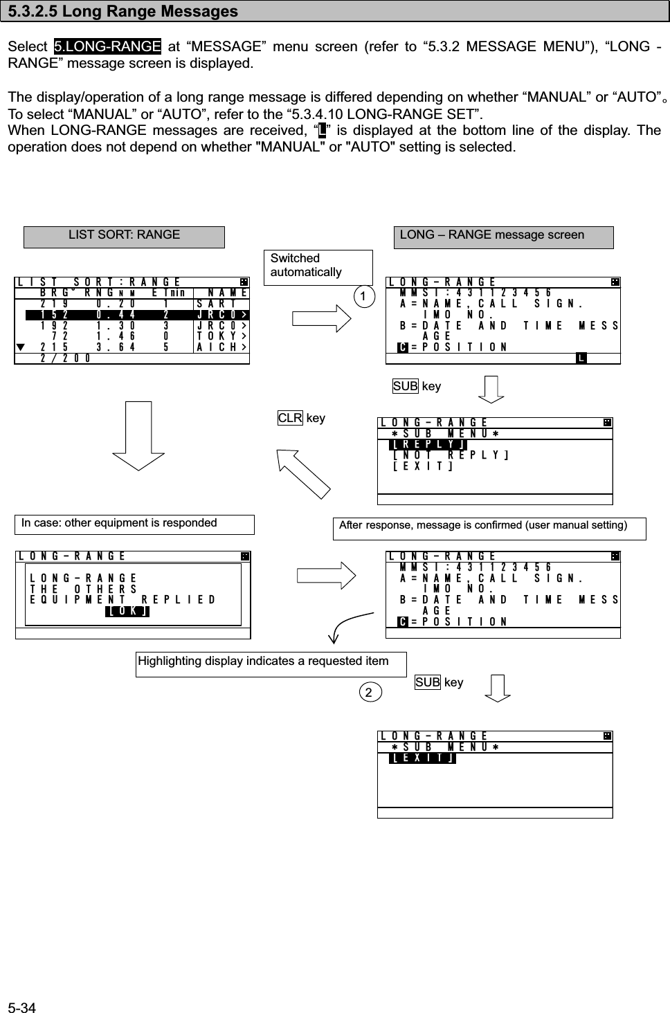
![5-35 a) MANUAL response condition While “MANUAL” is set, Long Range message screen is appears automatically on any screen after receiving a Long Range Request. In case other equipment responds, “THE OTHERS EQUIPMENT REPLIED” is displayed. If other equipment responds while displaying LONG-RANGE message screen, AIS displays the same message. Manual response operation (refer to Long Range message screen shown previously.) - When “LONG – RANGE” message screen is displayed, the requested contents are displayed. The operation after pressing SUB key is as follows: - Select [REPLY], AIS transmits the response containing contents for the request and then “L” is disappeared and the display switches to the Long Range message screen. - Select [NOT REPLY], the AIS will transmit the message that it is not going to reply and then “L” is disappeared and the display switches to the Long Range message screen. - Select [EXIT] or CLR key is pressed, Switched to LIST SORT: RANGE screen. b) AUTO response condition While “AUTO” is set in “4. SET UP” in MAIN MENU, the reply operation is performed at background. In this case, LONG RANGE message screen is not switched automatically. However “L” is displayed at the bottom line of the display. When confirming the message, the response has been already replied. Therefore after pressing SUB key at LONG RANGE” message screen, only [EXIT] is displayed at SUB menu screen. After EXIT is selected, “L” is disappeared.](https://usermanual.wiki/Japan-Radio/JHS-183.User-Manual-1/User-Guide-1846411-Page-61.png)
![5-37 5.3.3.1. Self Diagnosis Select 1.SELF DIAGNOSIS at “MAINTENANCE” menu screen (refer to “5.3.3 MAINTENANCE”), SELF DIAGNOSIS screen is displayed. In order to return to “MAINTENANCE” menu, press CLR key. 5'.( &+#)015+564#05210&'46'56 #..='06?4'57.61-%1061-Ť+06 )251-5'.( &+#)015+5Ţ64:1-251-#06'00#+06'40#.%10641..'4='06?Ť4'57.61-5'.( &+#)015+5Ţ%10641..'4 .#0='06?4'57.61-64#05210&'4 .1)%10641..'4 .1)%10641..'4 .#0 .1) Press key or key and select the unit for performing diagnosis test and press ENT key, and then test item for its self-diagnosis test can be selected. a) TRANSPONDER Select a desirable test item from the following items for 1.TRANSPONDER: TEST ALL: Test all the units. INT GPS: Test the internal GPS unit. TRX: Test the transceiver unit (TRX unit). PS: Test the PS unit is performed. Press ENT key at a desirable test item, and the cursor is moved [ENT]. In order to perform self-diagnosis, select [ENT] and press ENT key. Select [CANCEL], then the cursor is returned back without doing the test.](https://usermanual.wiki/Japan-Radio/JHS-183.User-Manual-1/User-Guide-1846411-Page-63.png)
![5-39 b) CONTROLLER Select 2.CONTROLLER at “SELF DIAGNOSIS” screen, and then press ENT key. In order to perform the self-diagnosis test, select [ENT], and then press ENT key. If you do not perform the self-diagnosis test, press key or key and select [CANCEL], and then the cursor is returned back without the test. When the result of the self-diagnosis test is normal, "OK" is displayed at RESULT:. - The diagnosis result The list of the diagnosis result is shown in the following table. Diagnosis Item Diagnosis Result Defective Unit Contents of Failure Corrective ActionNG SRAM CDJ-2983 SRAM error NG FROM CDJ-2983 Flash ROM error CONTROLLER NG CDJ-2983 Multiple errors in CDJ-2983 Replace CDJ-2983. c) CONTROLLER LAN Select 3.CONTROLLER LAN at “SELF DIAGNOSIS” screen, and then press ENT key. In order to perform the self-diagnosis test, select [ENT], and then press ENT key. If you do not perform the self-diagnosis test, press key or key and select [CANCEL], and then the cursor is returned back without the test. When the result of the self-diagnosis test is normal, "OK" is displayed at RESULT:. - The diagnosis result The list of the diagnosis result is shown in the following table. Diagnosis Item Diagnosis Result Defective Unit Contents of Failure Corrective ActionNG CPU FROM CDJ-2983 CPU internal Flash ROM error NG CPU DRAM CDJ-2983 CPU DRAM error NG CPU RAM CDJ-2983 CPU RAM error NG LAN CDJ-2983 LAN error CONTROLLER LAN NG CDJ-2983 Multiple errors in CDJ-2983 Replace CDJ-2983. [LOG DISPLAY OF SELF DIAGNOSIS RESULT] The past self-diagnosis results are displayed at 4.TRANSPONDER LOG,, 5.CONTROLLER LOG,, and 6.CONTROLLER LAN LOG, . When any of the logs are selected, the selected unit’s self-diagnosis results are displayed up to last 20 results. Log display order is displayed from first to 20th sequentially from a new result. Results and contents according to each diagnostic value are displayed as shown in the following figure. In the last diagnostic time is displayed. In addition,”--/-- --:--“ is displayed when time cannot be acquired. Press key or key to change to next page. %10641..'4 .1)%10641..'41-&#6' %10641..'40) 54#/Ť&#6' 64#05210&'4 .1)64#05210&'40)%1060)+06)251-Ť%10641..'4 .#0 .1)%10641..'4 .#01-&#6' %10641..'4 .#00) 54#/Ť&#6' ](https://usermanual.wiki/Japan-Radio/JHS-183.User-Manual-1/User-Guide-1846411-Page-65.png)
![5-40 5.3.3.2. Communication Test Select 2.COMMUNICATION TEST at “MAINTENANCE” menu screen (refer to “5.3.3 MAINTENANCE”) , “COMMUNICATION TEST” screen is displayed. The address MMSI can be set automatically from nearby ships, and then perform the communication test with others by response request. To switch to “MAINTENANCE” menu screen, press CLR key. In order to transmit communication confirmation contents, select [TX] and then press ENT key. After transmitted, its responded result is displayed. Responded --------------------- ACK: OK Not responded ---------------- ACK: NG Select [OK] in this Popup, and then press ENT key, and the screen is switched to “COMMUNICATION TEST” screen. Also “RESULT:“ on the bottom line in “COMMUNICATION TEST” screen is displayed the response result after transmission. Responded --------------------- RESULT: OK Not responded -----------------RESULT: NG Select [TX] %1//70+%#6+106'56019 64#05/+66+0) %1//70+%#6+106'56#%- 1-=1-?%1//70+%#6+10 6'56=6:?=%#0%'.?&'56+0#6+10//5+4'57.6Communication test screen](https://usermanual.wiki/Japan-Radio/JHS-183.User-Manual-1/User-Guide-1846411-Page-66.png)
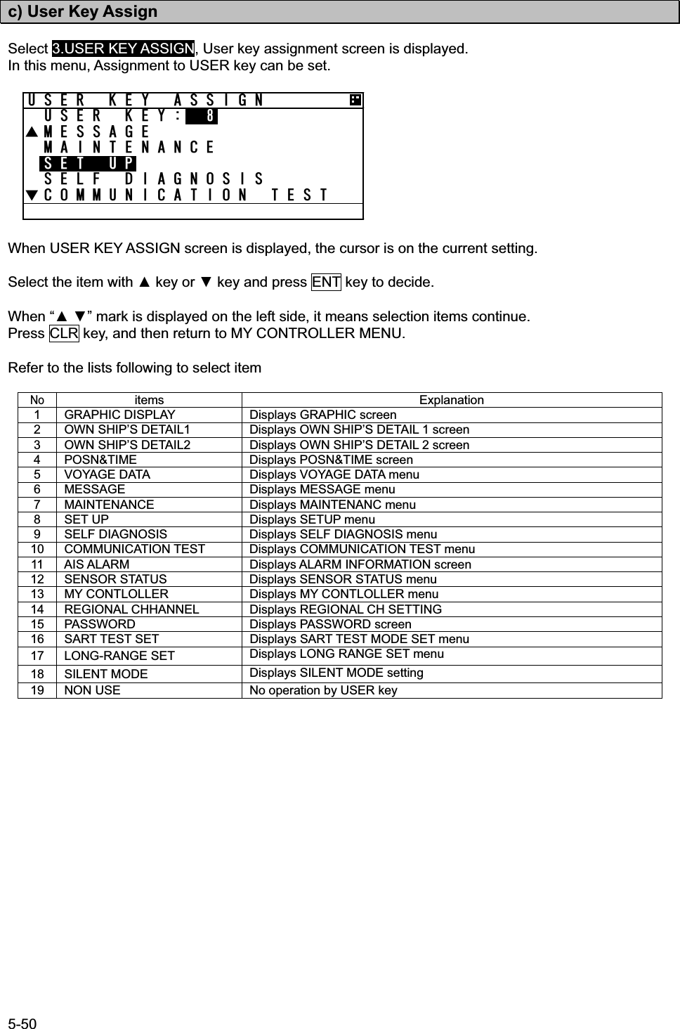
![5-54 b) Check of the setting Check the regional management setting whether it is based on the restriction or not. If there are no errors, the setting can be saved Press SUB key at the setting screen, SUB menu screen is displayed. CHECK 㨯㨯㨯㨯㨯 Check the setting whether it is based on the restriction or not SAVE 㨯㨯㨯㨯㨯㨯㨯 Save the setting, in case there are no problems. LIST 㨯㨯㨯㨯㨯㨯㨯㨯 See the saved data (up to 8 setting) CLEAR 㨯㨯㨯㨯㨯㨯 Clear the contents that is being set EXIT 㨯㨯㨯㨯㨯㨯㨯㨯 Leave the SUB menu and return to SET UP menu Select [CHECK] and push ENT key, the popup screen which shows the result is appeared. Result of checking Indication note OK [SAVE] can be selected NG 20NM>AREA,AREA>200NM The range is under 20NM or over 200NM. NG AREA CORNER ERROR(*1) Each of the distances of 3 area’s corners is within 8NM. NG AREA 500NM OVER Set the area separated 500NM from own ship’s location. NG CHANNEL ERROR Set by invalid channel NG OTHER ERROR Set by other invalid matters NG OVERTIME ERROR No response from transponder (*1)㧦In case of the condition below, AREA CORNER ERR is appeared. 㧦×㧦 57$MG[#TGC #TGC #TGC #TGC0QCTGC 0GYUGVVKPICTGC9KVJKPPOGCEJ CTGC’U EQTPGTYKVJKPPOGCEJ1-UETGGP0)UETGGP57$%.4MG[4')+10#. %*#00'.%* #%* $6:4: /1&' %* #$6:4: 6:4:6: 219'4*+)*Ť<10' 5+<'0/4')+10#. %*#00'.57$ /'07=%*'%-?=5#8'?=.+56?=%.'#4?=':+6?4')+10#. %*#00'.57$ /'07=%*'%-?=5#8'?=.+56?=%.'#4?=':+6?4')+10#. %*#00'.%*'%- 4'57.61-=1-?4')+10#. %*#00'.0) 0/ #4'##4'#0/=1-?](https://usermanual.wiki/Japan-Radio/JHS-183.User-Manual-1/User-Guide-1846411-Page-80.png)
![5-55 4')+10#. %*#00'.Ţ%* #%* $6:4: /1&'#$ 4: 6:4:6: 219'4*+)*Ť<10' 5+<'0/4')+10#. %*#00'.Ţ5174%'$41#&%#56 /5)//5+76% c) Save the setting If the result is OK, the setting is saved by transponder. While the result is “NG”, [SAVE] can not be selected. If the setting is saved normally, “SAVE OK” is appeared. d) Confirmation of saved data Select [LIST] in the SUB menu, Channel management information lists are displayed. The list can be scrolled by key or key. If CLR key is selected, the display is switched to SUB menu screen. If there are no saved data, “NO DATA” is appeared. Indicates the list number If there are or marks on the left side, This means the list continues. The last data indicates the time registered. e) Regional setting change If the regional channel setting is changed, Popup is appeared as shown below. 4')+10#. %*#00'.57$ /'07=%*'%-?=5#8'?=.+56?=%.'#4?=':+6?4')+10#. %*#00'.5#8' 1-=1-?%* /#0#)'/'06%*#0)'=1-?](https://usermanual.wiki/Japan-Radio/JHS-183.User-Manual-1/User-Guide-1846411-Page-81.png)
![5-57 a) Input name Select desirable number to change or register and Press ENT key and then the cursor move to SHIP NAME. Press ENT key at SHIP NAME, SHIP NAME input screen is displayed. Refer to “5.2.4 character input method“ to input. b) MMSI input After the inputting the name, select MMSI and press ENT key, and then MMSI can be inputted. MMSI can be inputted one digit at a time. (refer to 5.2.5 Numerical Input) After inputting the last digit, press ENT key and MMSI setting is finished. The screen move to next GROUP SHIP screen. c) Save and Clear This item is as follows SAVE 㨯㨯㨯㨯㨯㨯㨯㨯㨯㨯 Save the input after editing CLEAR 㨯㨯㨯㨯㨯㨯㨯㨯㨯 Erase the register which is selected or edited and switch to GROUP SHIP screen ALL CLEAR 㨯㨯㨯㨯㨯 Erase all registrations and switch to GROUP SHIP screen EXIT 㨯㨯㨯㨯㨯㨯㨯㨯㨯㨯㨯 Return to SET UP menu If [CLEAR] or [ALL CLEAR] are selected, Popup screen is appeared. (as shown below) If [OK] is selected, the registration is deleted. If [CANCEL] is selected, switch to previous screen. 5GNGEV=5#8'?)4172 5*+25*+2 0#/'//5+5*+2 0#/'#$%&'()*+,-./0123456789:;< =᳖?A!"@ =%?=#%?=1-?=':+6?)4172 5*+25*+2 0#/'//5+)4172 5*+257$ /'07=5#8'?=%.'#4?=#.. %.'#4?=':+6?)4172 5*+25#8' 1-=1-?)4172 5*+2#4' ;17 574'!=1-?=%#0%'.?](https://usermanual.wiki/Japan-Radio/JHS-183.User-Manual-1/User-Guide-1846411-Page-83.png)
![5-58 5.3.4.6 Change of Channels and Transmission Power (CHANNEL/POWER) Select 6.CHANNEL/POWER SET and enter password, Channels and power can be changed. Caution㧦Normally, AIS is operated by regulated channels. Ship’s administrators must be responsible for any change. a) Password input Password is composed of alphabet “A㨪Z” and numeric “0㨪9”. After the 4 digits are input, then the cursor moves to [ENT]. If [ENT] is selected, Channels and power changing screen is displayed. If [EXIT] is selected, switch to SET UP screen. b) Channels and power change Set the channel number and select transmission power After channel and power changing screen is displayed, the cursor is on 1.CH A. Select 1. CH A and press ENT key. The cursor move to on the left side of channel number. Refer to 5.2.5 character input method to input. Press ENT key on the right side of the channel number, the cursor moves to next item. (2.CH B takes same procedure.) Transmission power is selected as shown below. HIGH㨯㨯㨯㨯㨯㨯㨯normal power LOW㨯㨯㨯㨯㨯㨯㨯1W Select the power and press ENT key. The cursor moves to [SET]. If [SET] is selected, AIS starts operation by the setting. If [EXIT] is selected, switch to SET UP screen. If invalid channels are inputted or it can not be set, error popup screen (same as “5.3.4.3 Regional channel setting”) is appeared. x The transmission power set here is not the same as that of “5.3.4.4 POWER REDUCTION” and the AIS will continue operation by the set power and is not dependent on the distance moved. x The setting changed in this menu is reverted to default by restarting the equipment. %*#00'.219'42#55914&#$%&'()*+,-./0123456789:;< =᳖?A!"@ ='06?=':+6?Input field %*#00'.219'4%* #%* $219'4*+)*=5'6?=':+6?%*#00'.219'4%*#00'. '4414=1-?](https://usermanual.wiki/Japan-Radio/JHS-183.User-Manual-1/User-Guide-1846411-Page-84.png)
![5-59 5.3.4.7 Change Password (PASSWORD) Select 7. PASSWORD, Password screen is displayed. In this menu, set the password that is used in case power off or channel change. The password is managed by ship’s administrator. Select 1.USER LEVEL and press ENT key. If CLR is selected, the display is switched to SET UP menu screen. 1. The cursor is on the right side of “OLD” and another cursor is displayed in the character pad at the same time. 2. Input the current password after “OLD:” by using character pad. 3. After 4 digits input, select [ENT] and press ENT key. If the password is not matched with current one, the cursor returns to the first digit. Factory default password is set “0000”. If the password is matched with current one, the cursor move to first digit of “NEW”. 4. Input the new 4 digits password at ”NEW:” 5. Press ENT key at last digit If [ENT] is selected, new screen is appeared and the cursor is at [SAVE]. If [EXIT] is selected, discard the input and return to PASSWORD screen. 6. At the above screen Select [SAVE], new password is saved and display switches to SET UP menu Select [EXIT] , discards the input and display switches to the PASSWORD screen. If password setting is not completed, Popup screen (as shown left) appears. In this case, Select [SAVE] again or change to another password. Note) Password is composed of alphanumeric “A㨪Z” and “0㨪9”. 2#55914&75'4 .'8'.75'4 .'8'.1.& 0'9 #$%&'()*+,-./0123456789:;< =᳖?A!"@ ='06?=':+6?75'4 .'8'.1.& 0'9 =5#8'?=':+6?75'4 .'8'.4'57.65'6 0)=1-?](https://usermanual.wiki/Japan-Radio/JHS-183.User-Manual-1/User-Guide-1846411-Page-85.png)
![5-61 a) Setting of long range management Select 1.LR BROADCAST, Long range broadcast can be set. AIS transmits own ship’s position or navigation status by long range broadcasting (using satellite etc.) The channels are specified in item 2.3. The AIS will respond, in cases where a coast radio station requests own ship's information. Select from ON or OFF with key or key. ON 㨯㨯㨯㨯㨯㨯㨯㨯 Transmit the response by the setting channel (set at item 2.3) . OFF 㨯㨯㨯㨯㨯㨯㨯 Not transmit the response. But requested by LR port, Output the response through LR port. Press ENT key to decide after selection Set the channel to transmit for long range response. Input the channel number one digit at a time. (Refer to “5.2.5 numerical input”) Factory default settings are 2075ch and 2076ch. b) Setting of long range response Select 4.LONG-RANGE, Long range response can be set. Long range transmission operates in cases where the AIS is connected to equipment that supports long range transmission. In this menu the response type shown in paragraph 5.3.2.5 "Confirmation of long range message" refers. AUTO: Respond automatically MANUAL: Respond by manual c) Save the setting Save the setting of item from 1 to 4. Select [SET], save the setting and switch to SET UP menu. Select [EXIT], discard the setting and switch to the SET UP menu. .10)4#0)'.4 $41#&%#561((%* #%* $.10)4#0)'#761=5'6?=':+6?Ť.10)4#0)'.4 $41#&%#561((%* #%* $.10)4#0)'#761=5'6?=':+6?.10)4#0)'.4 $41#&%#561((%* #%* $.10)4#0)'/#07#.=5'6?=':+6?Ť.10)4#0)'.4 $41#&%#561((%* #%* $.10)4#0)'/#07#.=5'6?=':+6?](https://usermanual.wiki/Japan-Radio/JHS-183.User-Manual-1/User-Guide-1846411-Page-87.png)
![5-63 5.3.4.13 Initial Setting of Own Ship’s Heading Direction㧔NSK UNIT㧕 When the NSK unit (gyro interface option) is installed, then the heading direction needs to be set. This item is displayed when AIS is connected with NSK unit and its setting is available. Select 10. NSK UNIT, Own ship’s heading and the setting of NSK UNIT are displayed. If CLR key is selected, the display will switch to the SET UP menu. In this menu, Item 1.HEADING value can only be set. Other items (from 2 to 8) show current NSK unit’s setting and alarm information. a) Initial value input of heading Select 1.HEADING, Heading value can be set. The value is between 000.0° to 359.9° and input one digit at a time by using UP/DOWN key. After all digits input, Press SUB key and then SUB menu is appeared. In this SUB menu Select [SET], saves the heading value and switches the display to SET UP menu. Select [EXIT], Discards the input and switches the display to the NSK UNIT menu. Caution: In case some alarm occurred at NSK unit and NSK is recovered, this screen is displayed and setting the heading value is necessary. If the display is switched to another screen without the NSK being set, the AIS will request the heading input on a regular basis. Therefore this screen is displayed again. 57$MG[%.4MG[57$MG[05- 70+6*'#&+0)c#.#4/241)/'9'446;2'56'24#6+1:&+4'%6+10014/Ť05- 70+6Ţ176276 6+/+0)/55+/7.#614'44 6+/+0)505- 70+657$ /'07=5'6?=':+6?05- 70+6*'#&+0)c#.#4/241)/'9'446;2'56'24#6+1:&+4'%6+10014/Ť](https://usermanual.wiki/Japan-Radio/JHS-183.User-Manual-1/User-Guide-1846411-Page-89.png)