Itron 962 User Manual Installation Information
Silver Spring Networks Installation Information
UserManual.wiki
>
Itron
>
962 User Manual
>
Installation Information
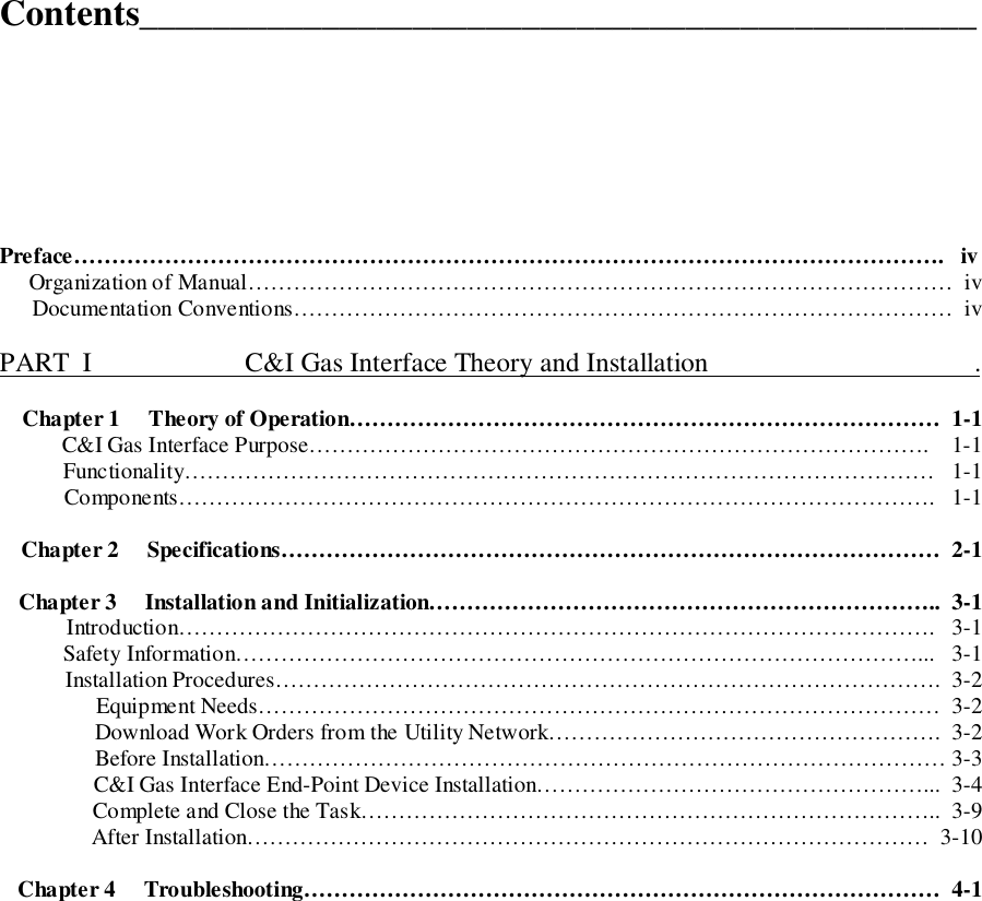
Contents
1.
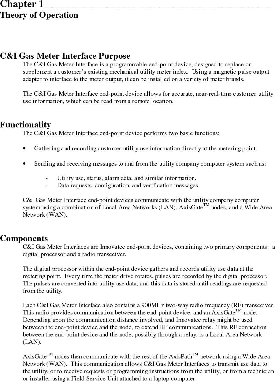
Operational Description
2.
Revised Manual
3.
Installation Information
Installation Information
Navigation menu
Upload a User Manual
Namespaces
Wiki Guide
HTML
PDF
Info
Views
User Manual
Discussion / Help
Navigation