Itron 921 Gateway/Telco User Manual Utility Network Operational Manual
Silver Spring Networks Gateway/Telco Utility Network Operational Manual
Itron >
Contents
- 1. User Manual
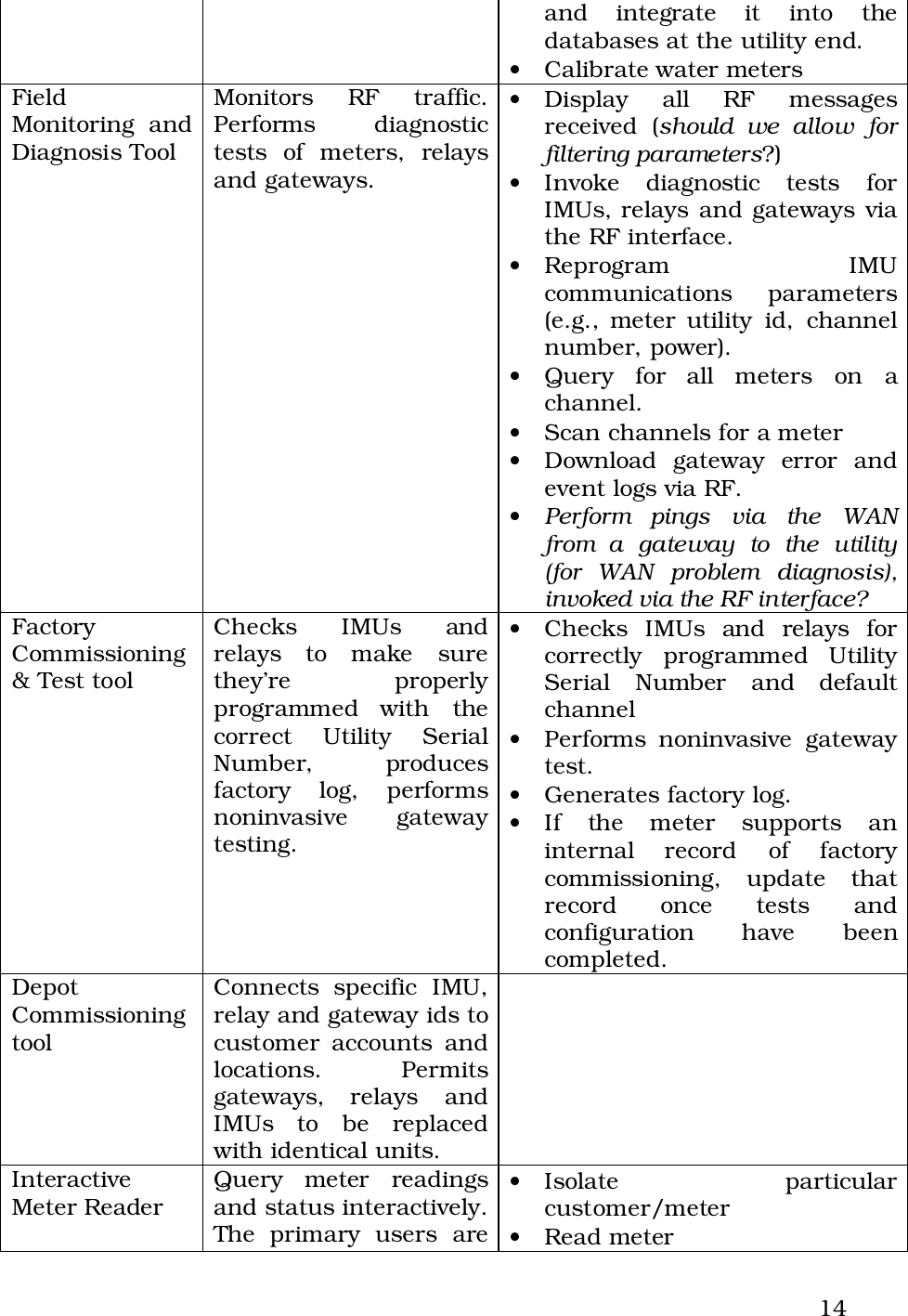
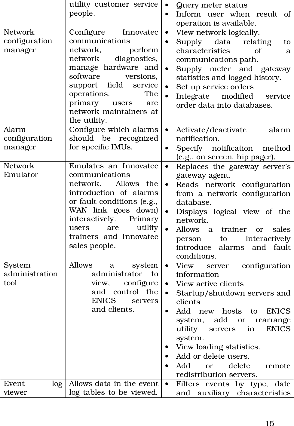
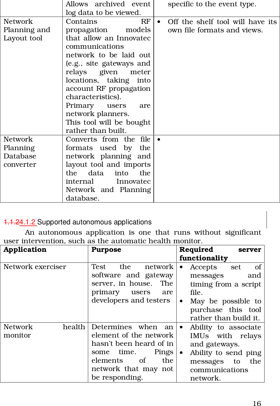
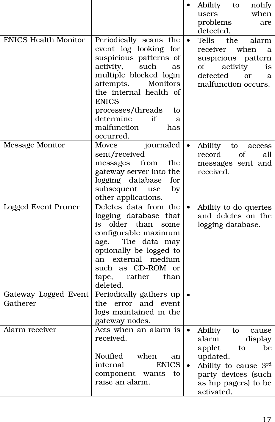
- 2. Utility Network Operational Manual
- 3. Modem User Manual
Utility Network Operational Manual