Itron 921 Gateway/Telco User Manual Modem
Silver Spring Networks Gateway/Telco Modem
UserManual.wiki
>
Itron
>
921 User Manual
>
Modem User Manual
Contents
1.
User Manual
2.
Utility Network Operational Manual
3.
Modem User Manual
Modem User Manual
Navigation menu
Upload a User Manual
Namespaces
Wiki Guide
HTML
PDF
Info
Views
User Manual
Discussion / Help
Navigation


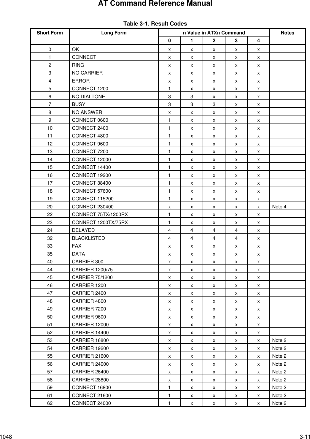
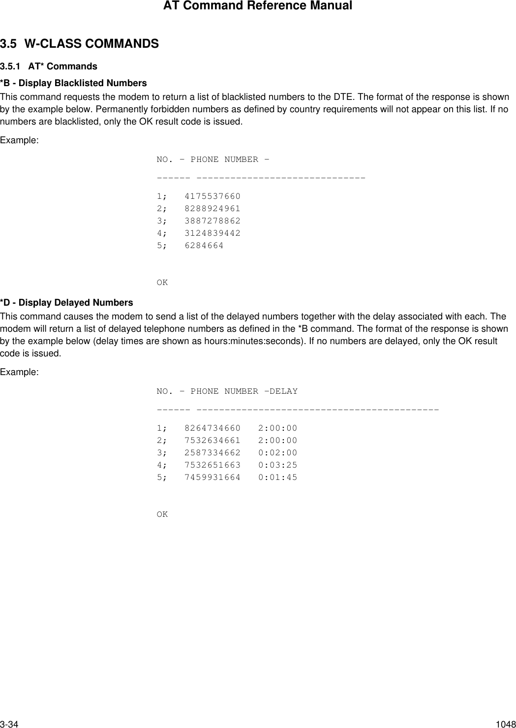
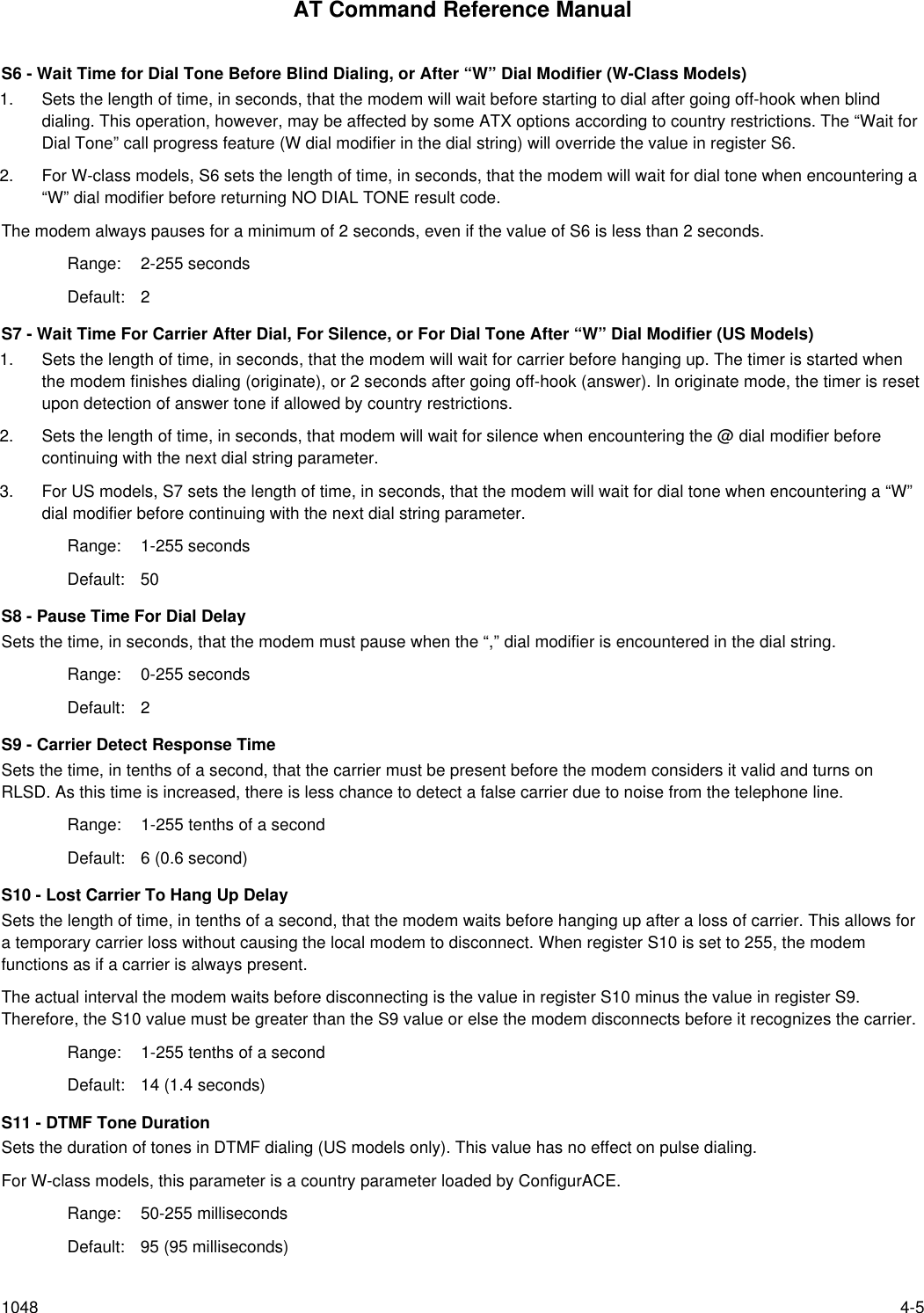
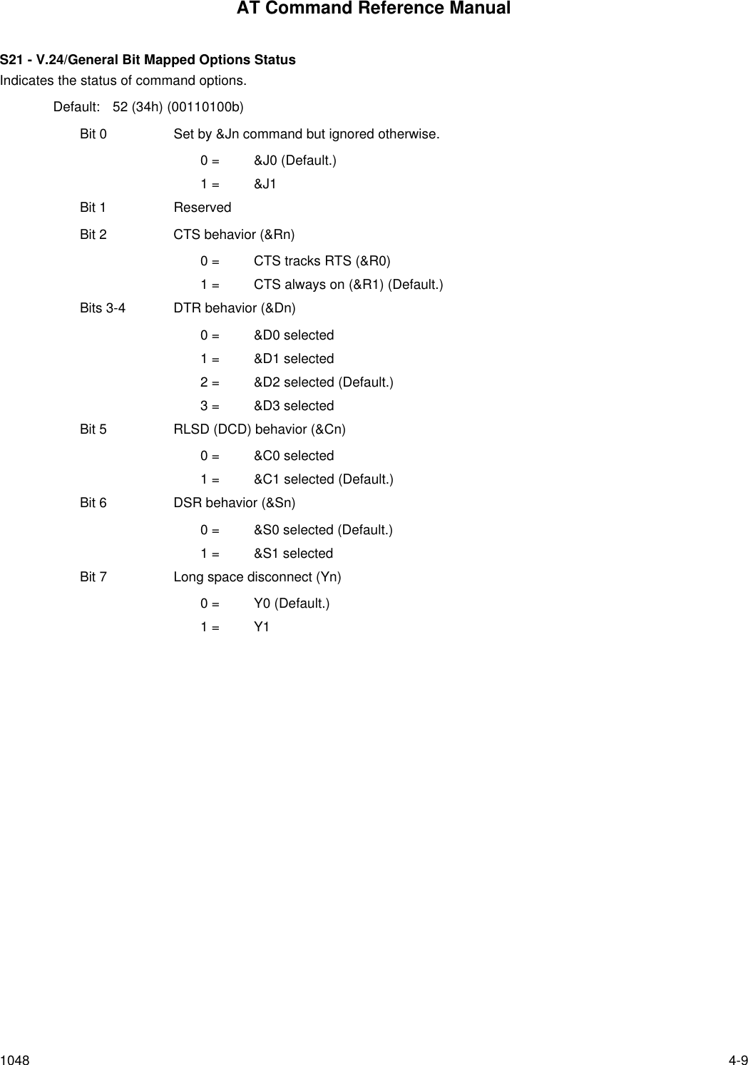
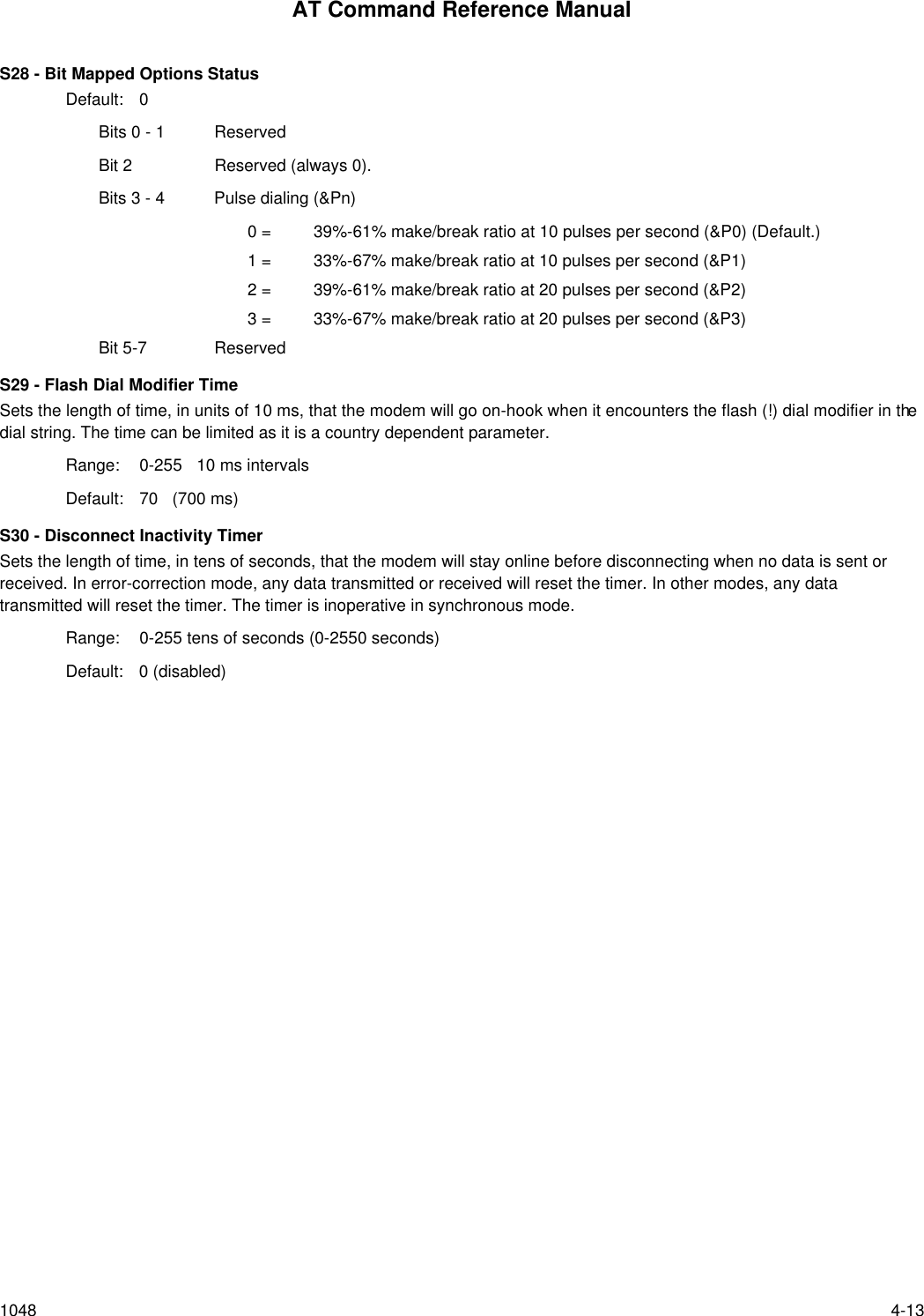
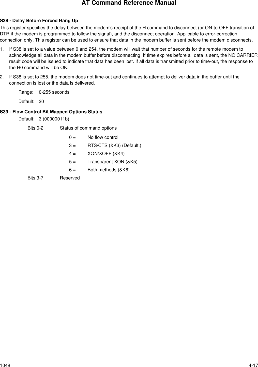
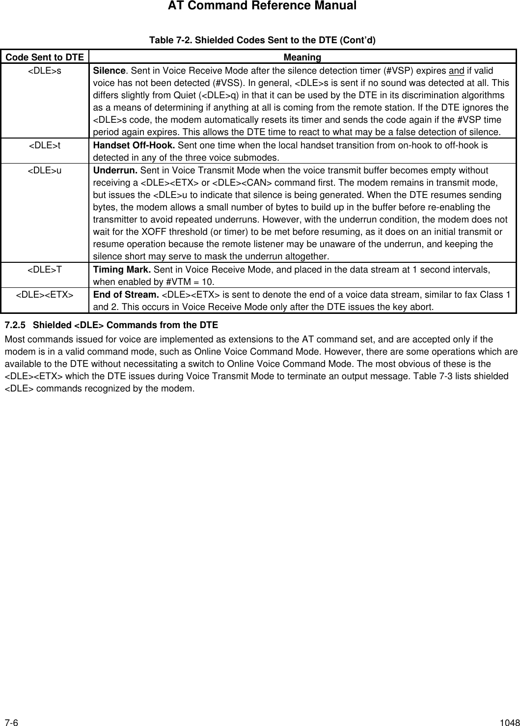
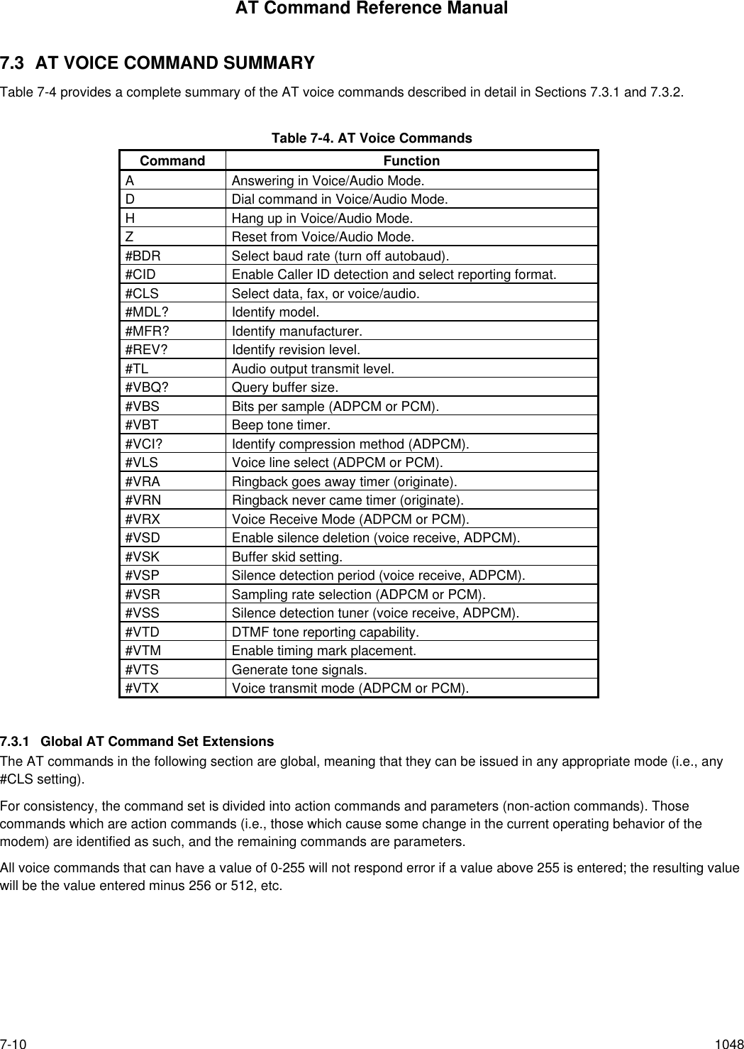
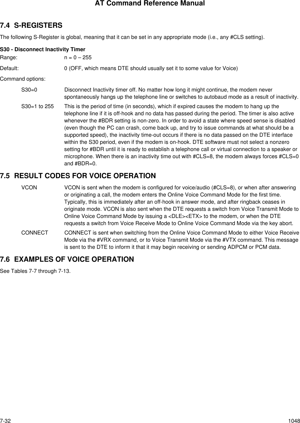
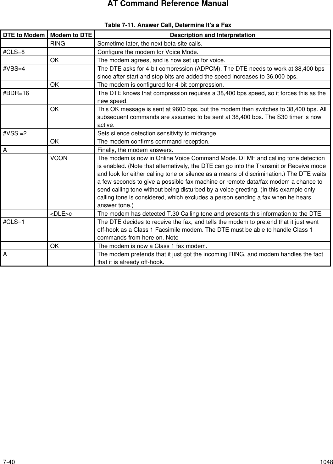
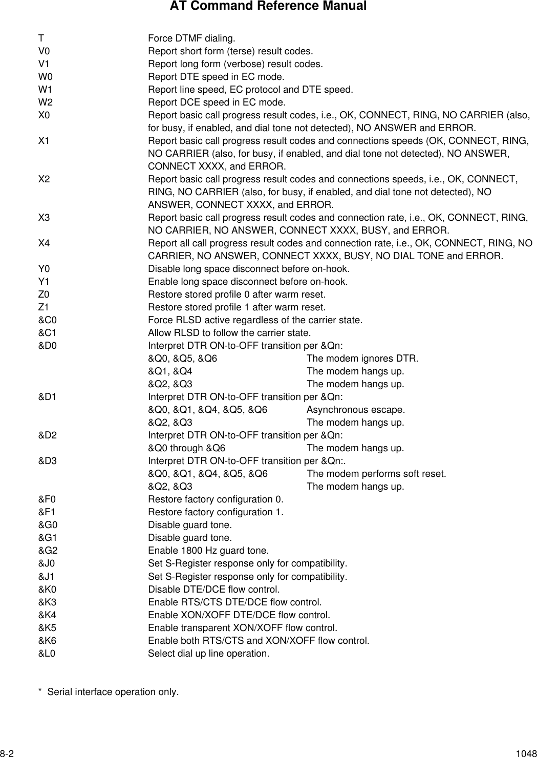
![AT Command Reference Manualxii 1048Voice to Data........................................................................................................................................7-9Unsuccessful Data Connection Attempt to Voice...................................................................................7-97.2.10 Caller ID ................................................................................................................................................7-97.3 AT VOICE COMMAND SUMMARY.....................................................................................................................7-107.3.1 Global AT Command Set Extensions .....................................................................................................7-10ATA - Answering in Voice/Audio..........................................................................................................7-11ATD - Dial Command in Voice/Audio...................................................................................................7-11ATH - Hang Up in Voice/Audio............................................................................................................7-11ATZ - Reset from Voice Mode.............................................................................................................7-12#BDR - Select Baud Rate (Turn off Autobaud) ....................................................................................7-12#CID - Enable Caller ID Detection and Select Reporting Format.........................................................7-12#CLS - Select Data, Fax, or Voice/Audio.............................................................................................7-14#MDL? - Identify Model.......................................................................................................................7-14#MFR? - Identify Manufacturer ...........................................................................................................7-14#REV? - Identify Revision Level..........................................................................................................7-147.3.2 AT#V Commands Enabled Only in Voice Mode (#CLS=8) ......................................................................7-15#TL- Audio Output Transmit Level ......................................................................................................7-15#VBQ? - Query Buffer Size.................................................................................................................7-15#VBS - Bits Per Sample......................................................................................................................7-15#VBT - Beep Tone Timer....................................................................................................................7-16#VCI? - Identify Compression Method.................................................................................................7-16#VLS - Voice Line Select .................................................................................................................... 7-17#VRA - Ringback Goes Away Timer (Originate) ..................................................................................7-19#VRN - Ringback Never Came Timer (Originate) ................................................................................7-19#VRX - Voice Receive ........................................................................................................................7-19#VSD - Enable Silence Deletion (Voice Receive) [ADPCM] .................................................................7-20#VSK - Buffer Skid Setting.................................................................................................................. 7-20#VSP - Silence Detection Period (Voice Receive) [ADPCM] ................................................................7-21#VSR - Sampling Rate Selection.........................................................................................................7-21#VSS - Silence Detection Tuner (Voice Receive) [ADPCM] .................................................................7-22#VTD - DTMF Tone Reporting ............................................................................................................7-23#VTM - Enable Timing Mark Placement ..............................................................................................7-24#VTS - Generate Tone Signals (Online Voice Command) ...................................................................7-24#VTX - Voice Transmit........................................................................................................................ 7-25#VGT - Set Playback Volume in the Command State.......................................................................... 7-25<DLE><u> and <DLE><d> - Set Playback Volume in the Data State...................................................7-257.3.3 Speakerphone Commands ....................................................................................................................7-25Originating a Call in Speakerphone Mode ...........................................................................................7-26Answering a Call in Speakerphone Mode............................................................................................7-26Muting the Local Handset During Phone Conversation - Music on Hold...............................................7-26Recording a Handset Conversation on the Phone Line........................................................................7-27Recording/Playback from Handset through Sound Chip ......................................................................7-27#SPK Parameter ................................................................................................................................7-27Room Monitor.....................................................................................................................................7-29Switching Between #VLS Settings.......................................................................................................7-29Reporting of Local Handset Status......................................................................................................7-297.3.4 Using VoiceView with Speakerphone, Headset, and Handset modes......................................................7-30Using Modem as Dialer Prior to VoiceView Mode................................................................................7-317.4 S-REGISTERS ...................................................................................................................................................7-32S30 - Disconnect Inactivity Timer........................................................................................................7-327.5 RESULT CODES FOR VOICE OPERATION.......................................................................................................7-327.6 EXAMPLES OF VOICE OPERATION .................................................................................................................7-328. AT COMMAND SET SUMMARY...................................................................................................................................8-18.1 BASIC AT COMMANDS........................................................................................................................................8-18.2 ECC COMMANDS................................................................................................................................................8-48.3 MNP 10 COMMANDS...........................................................................................................................................8-5](https://usermanual.wiki/Itron/921.Modem-User-Manual/User-Guide-100350-Page-12.png)
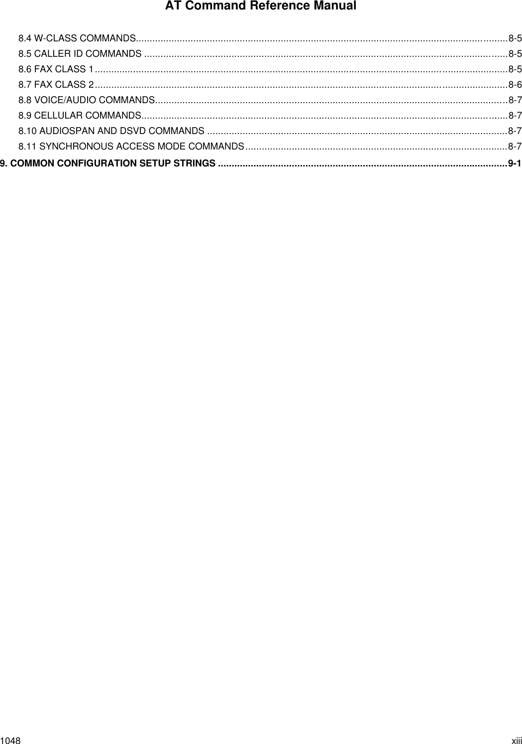
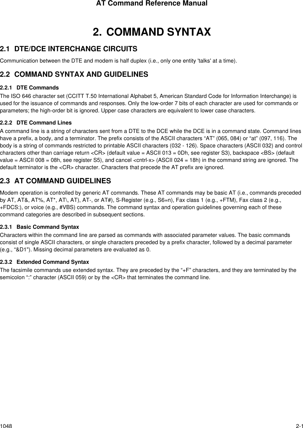

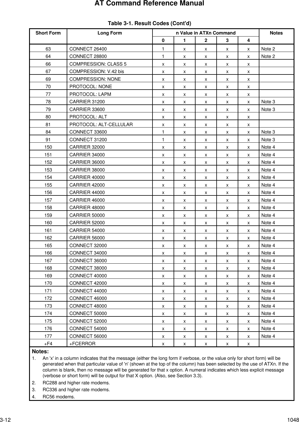
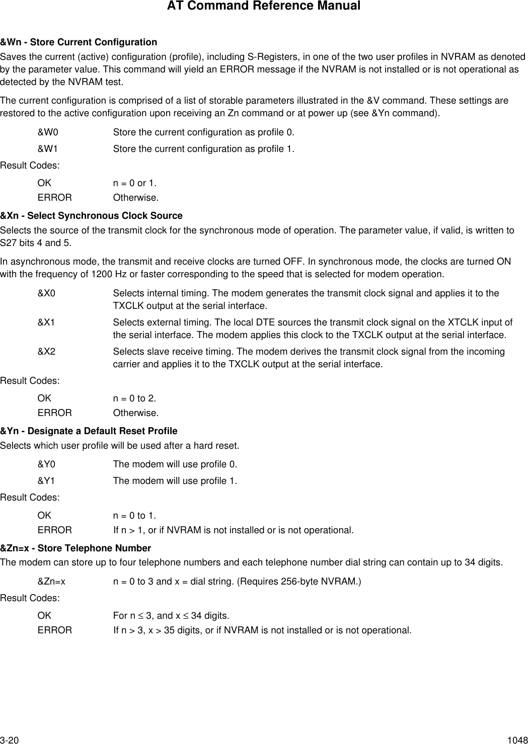
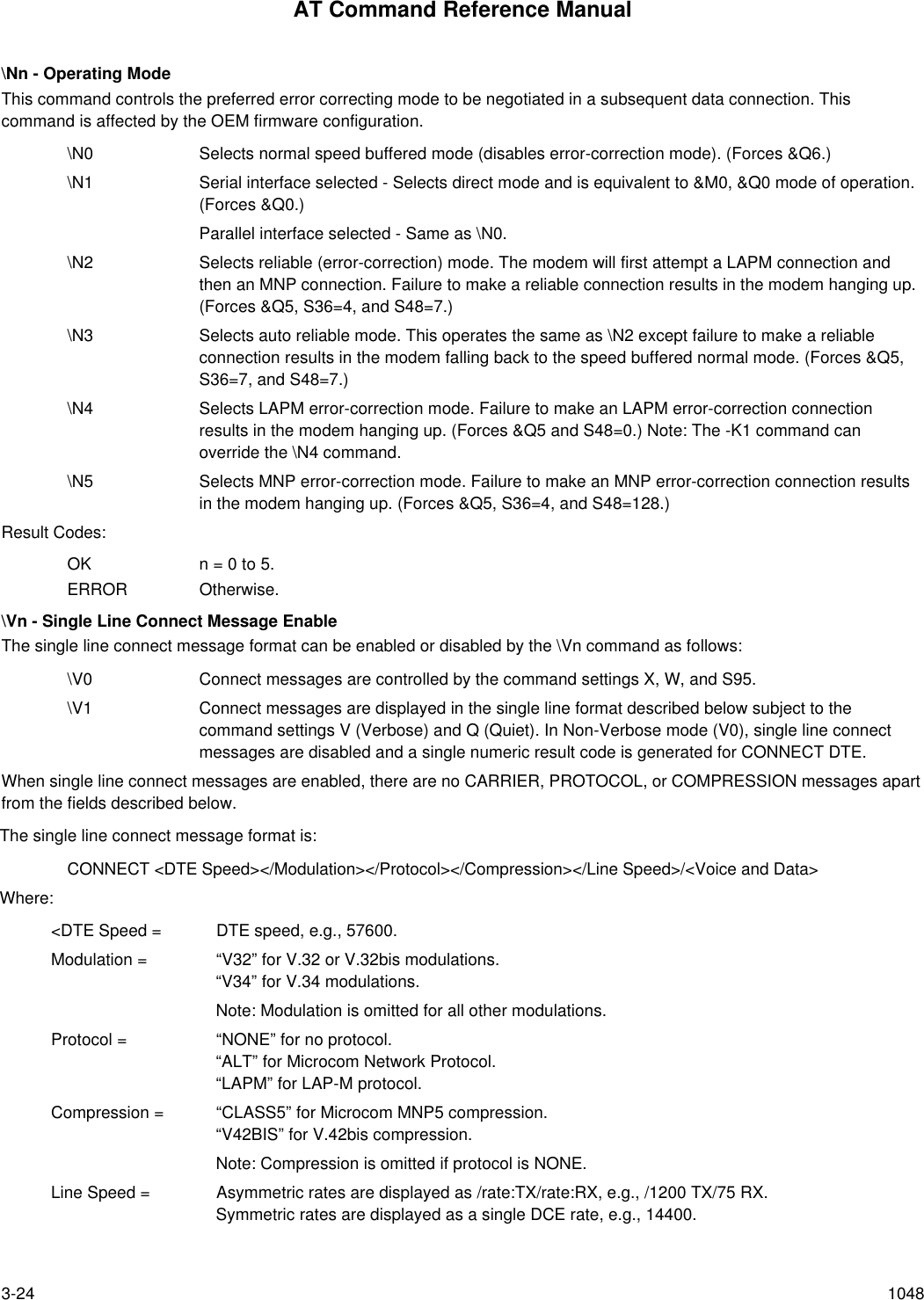
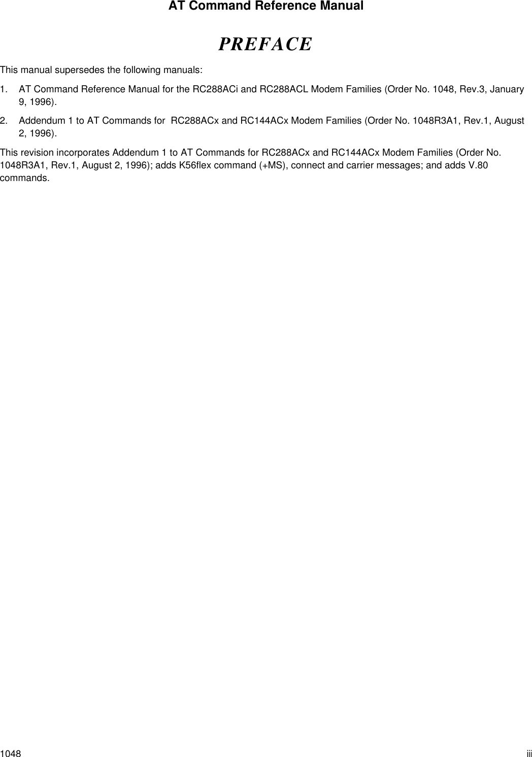
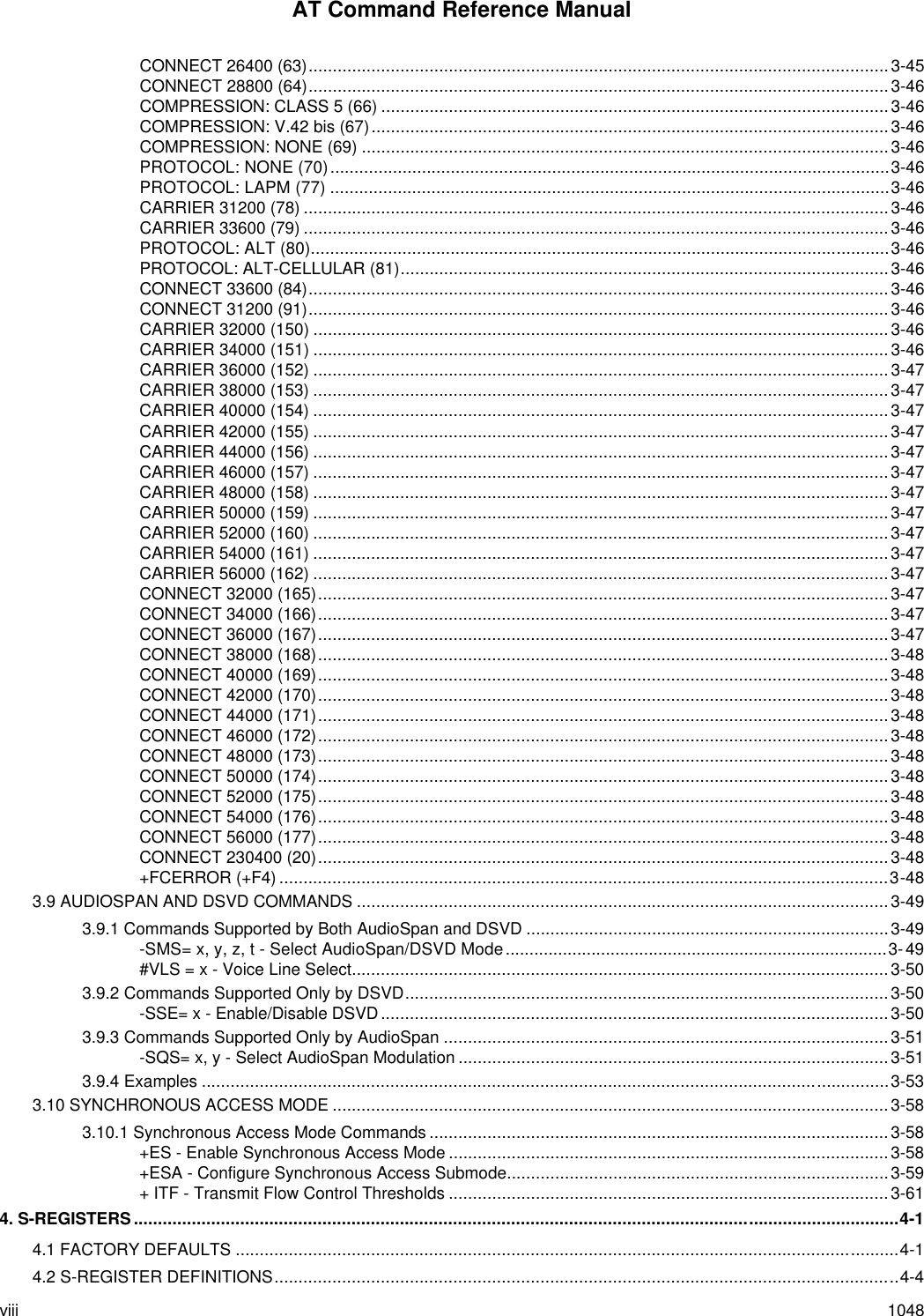
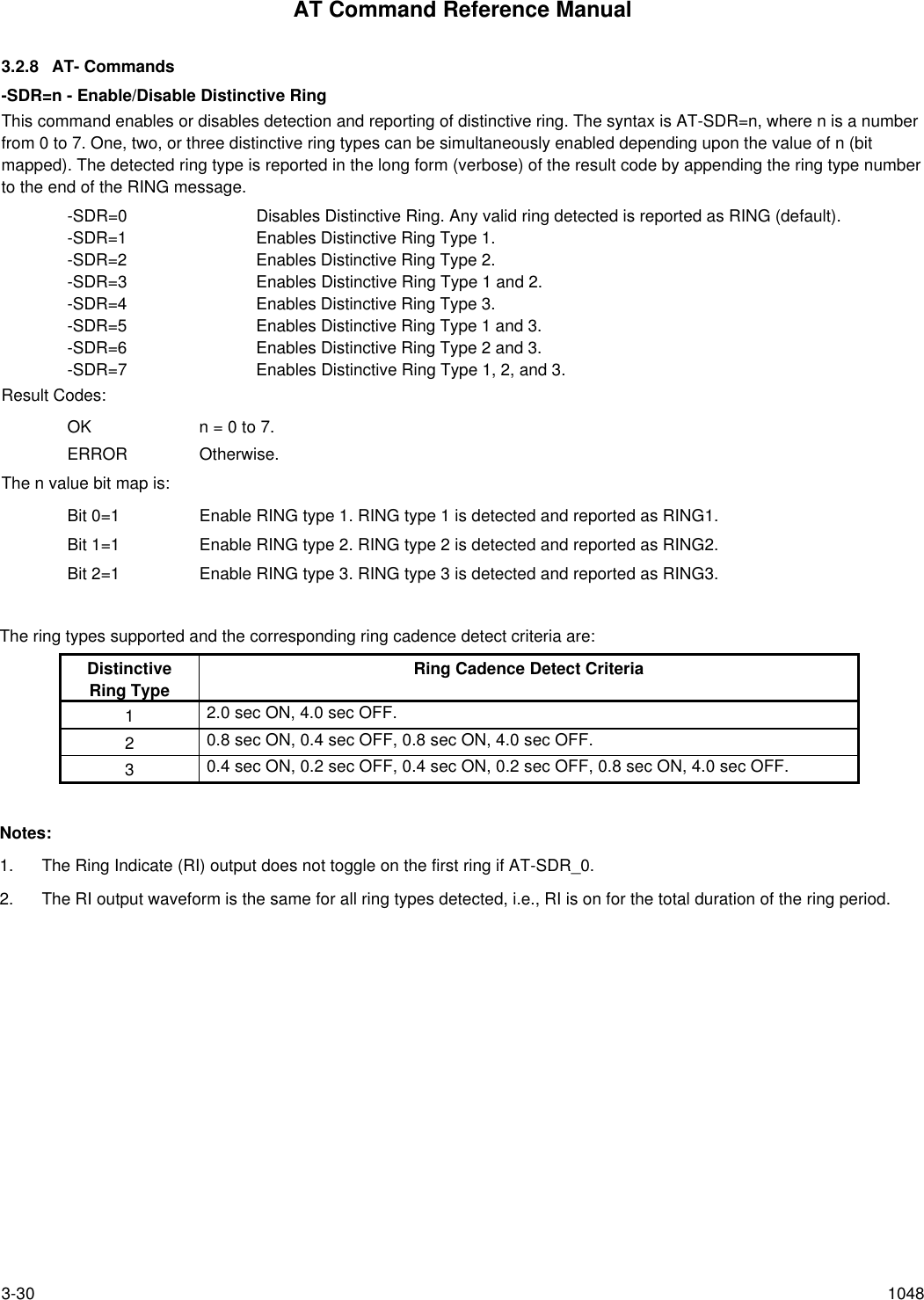
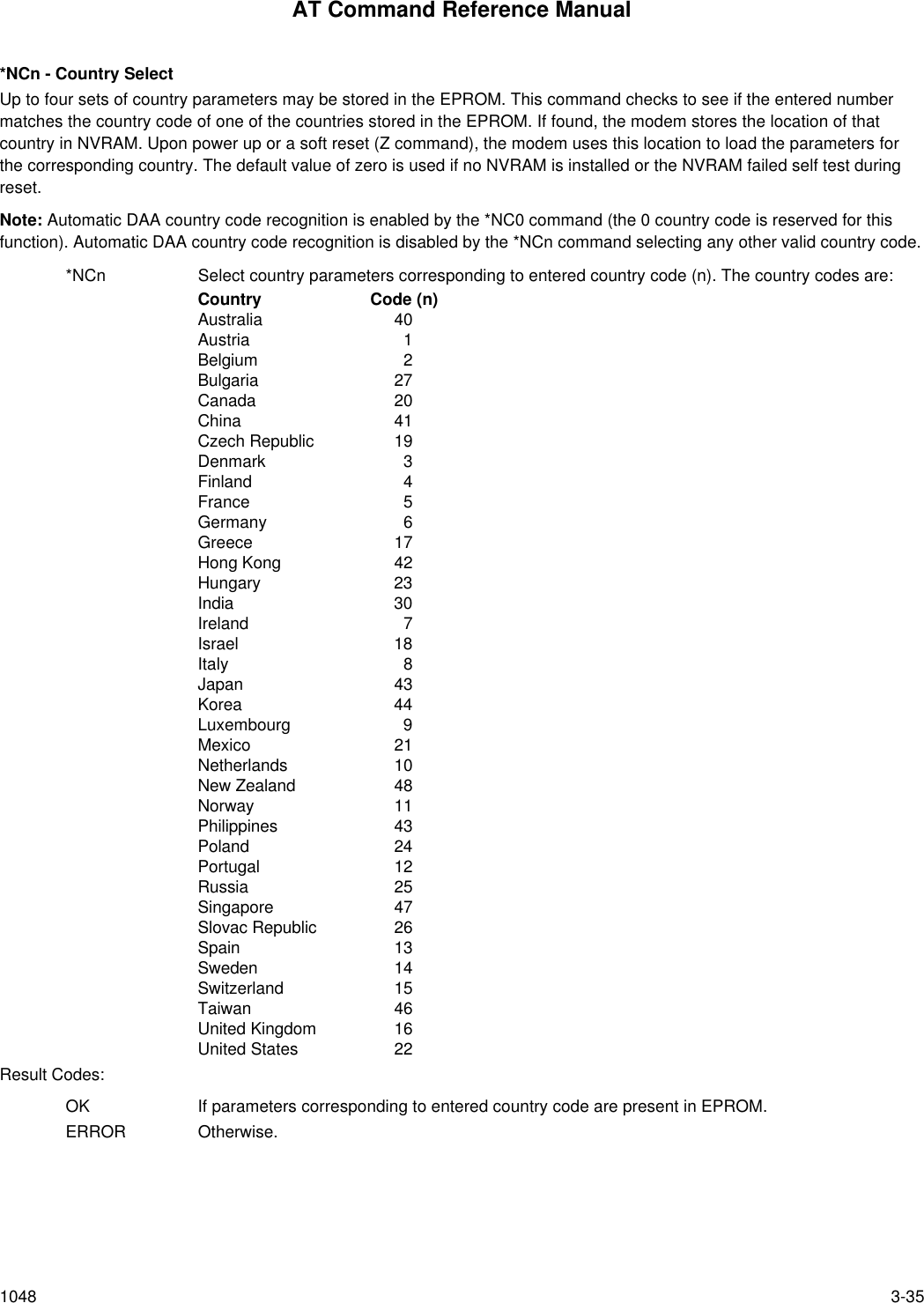
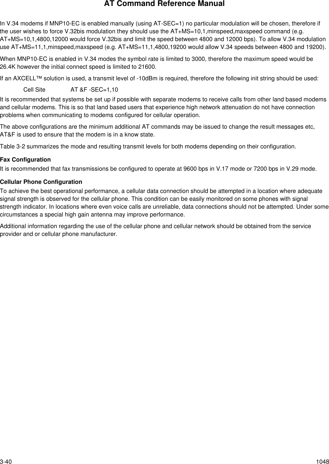
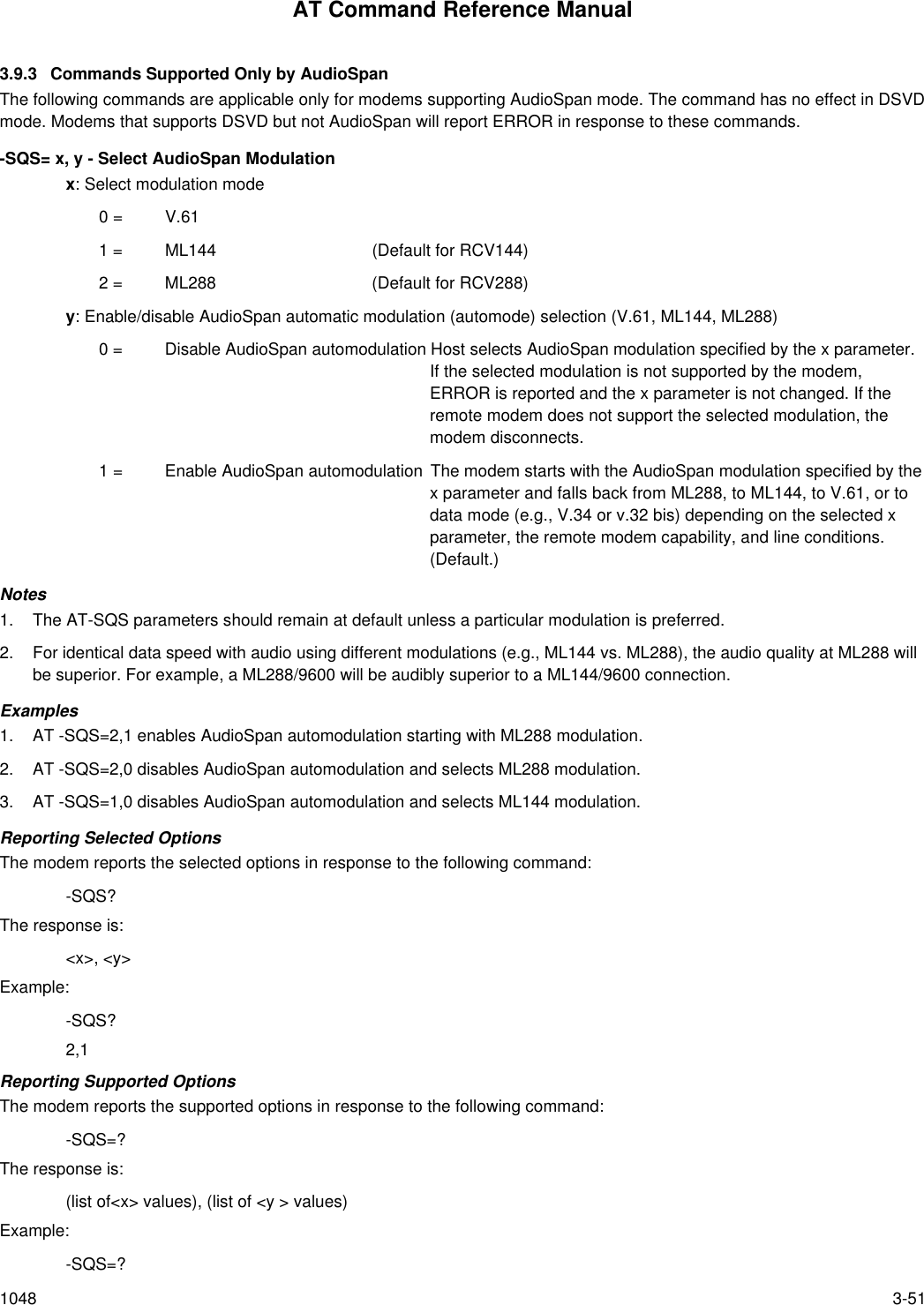
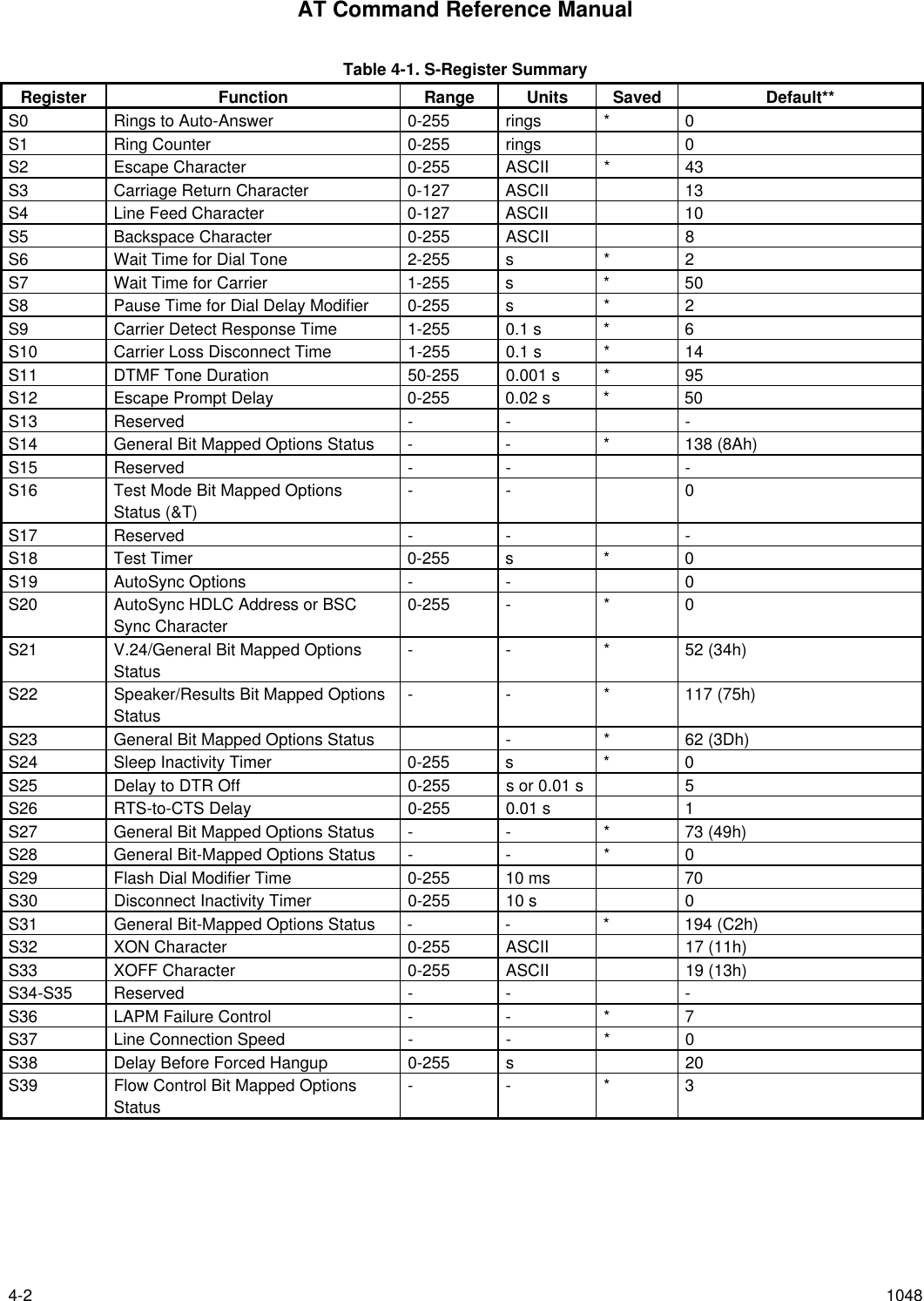
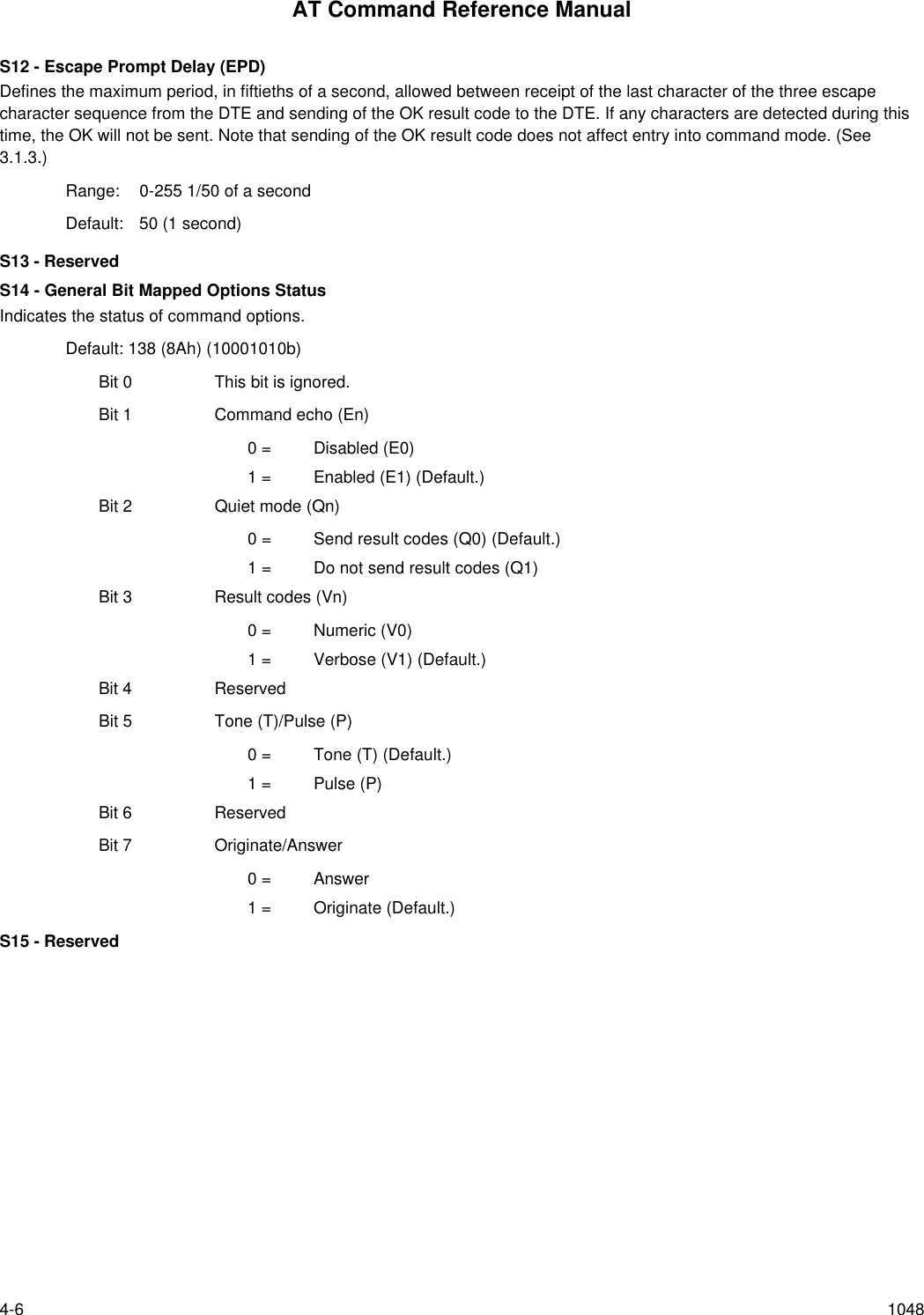
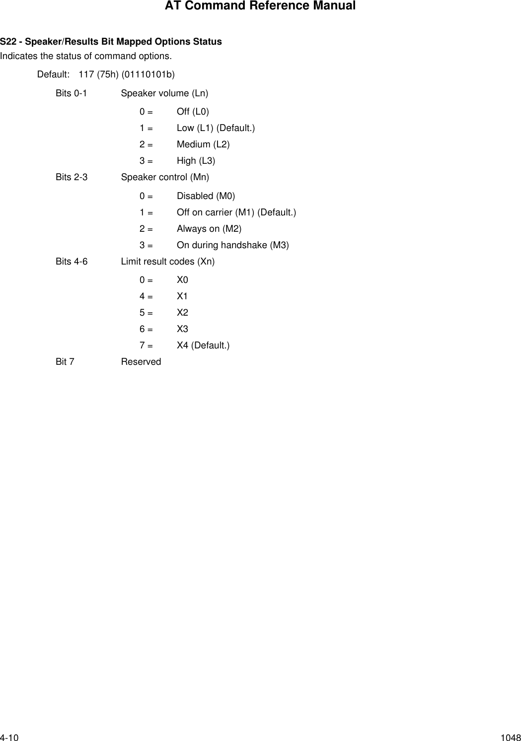
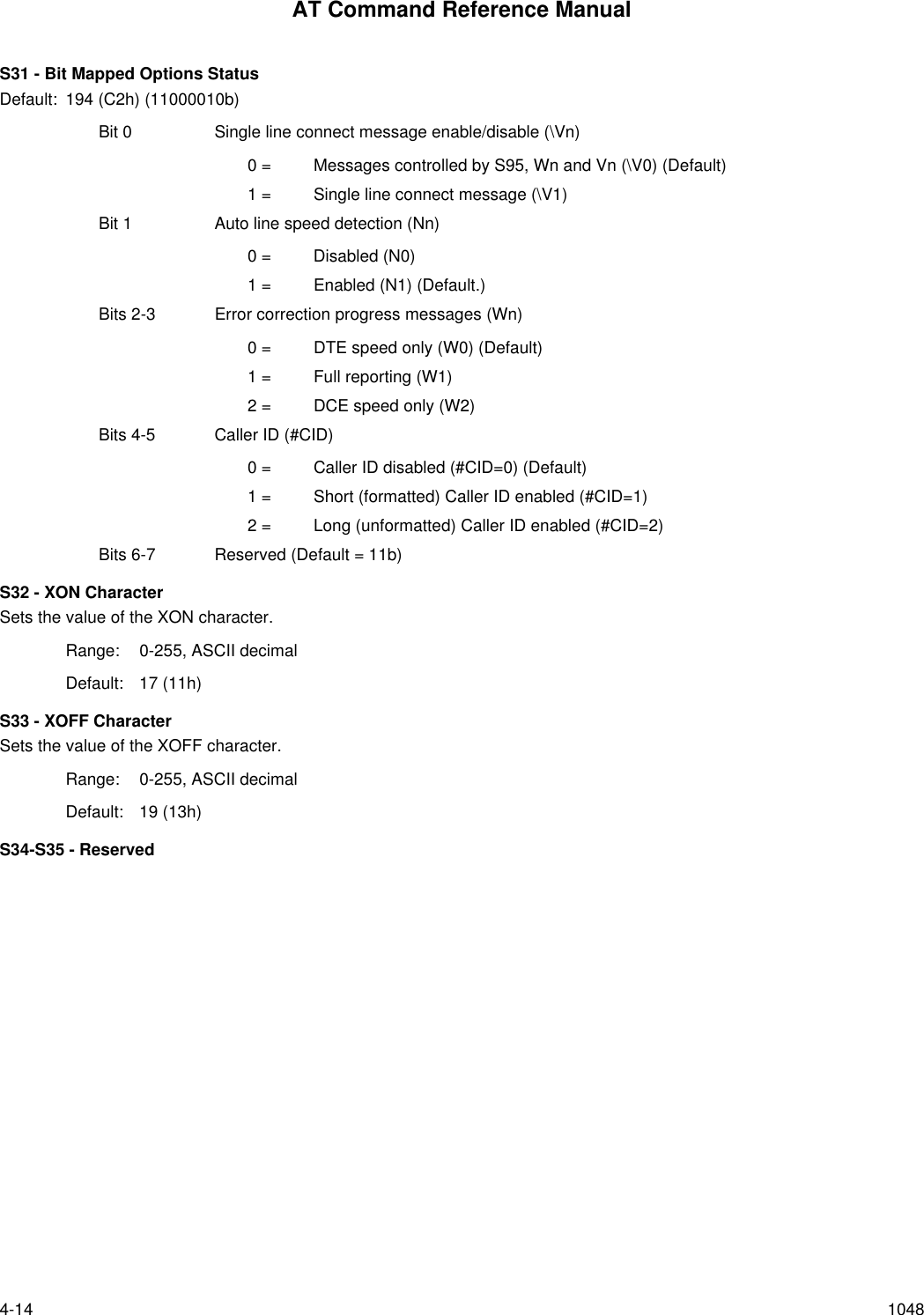
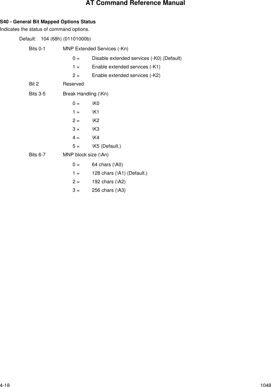
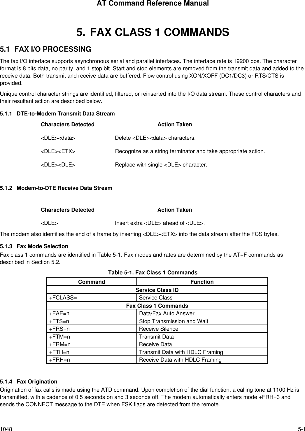
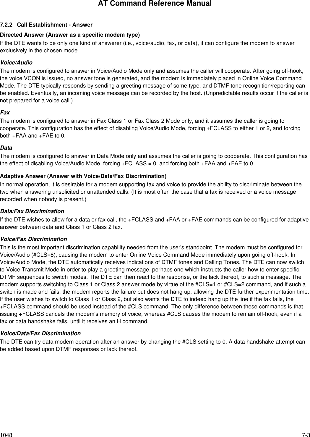
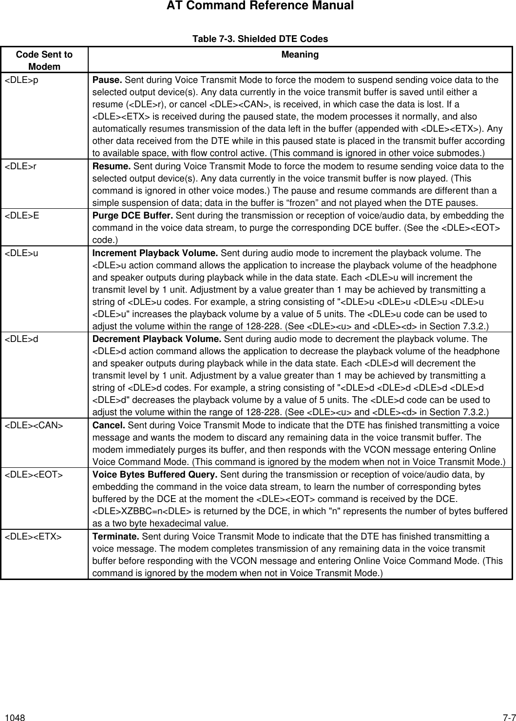
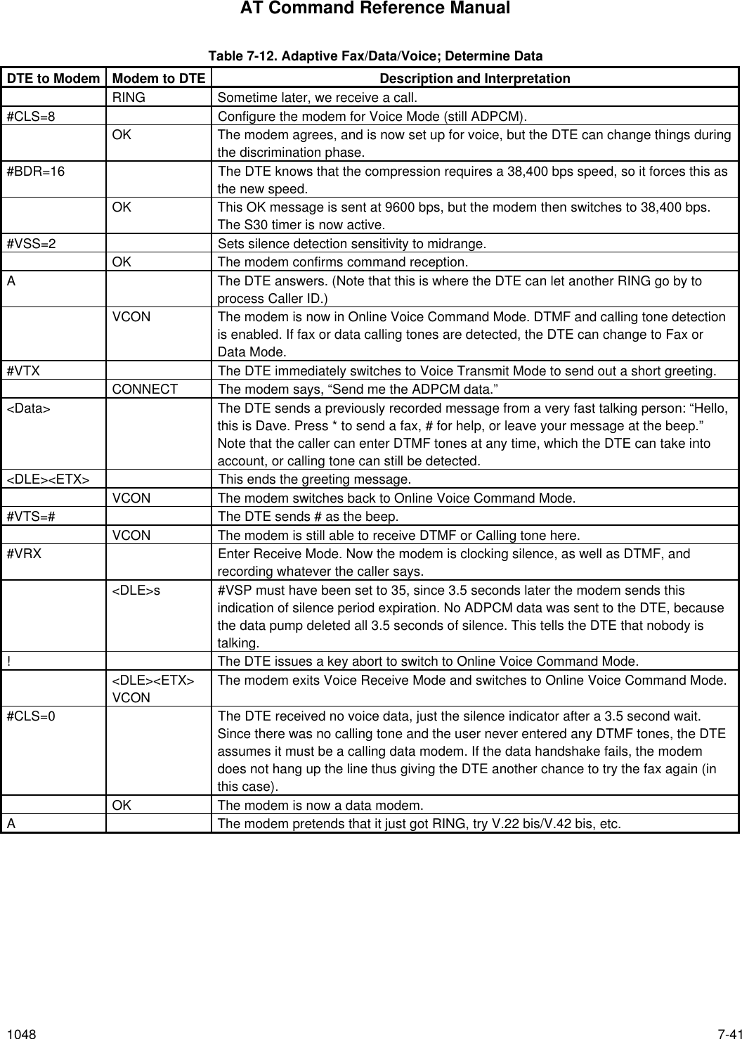
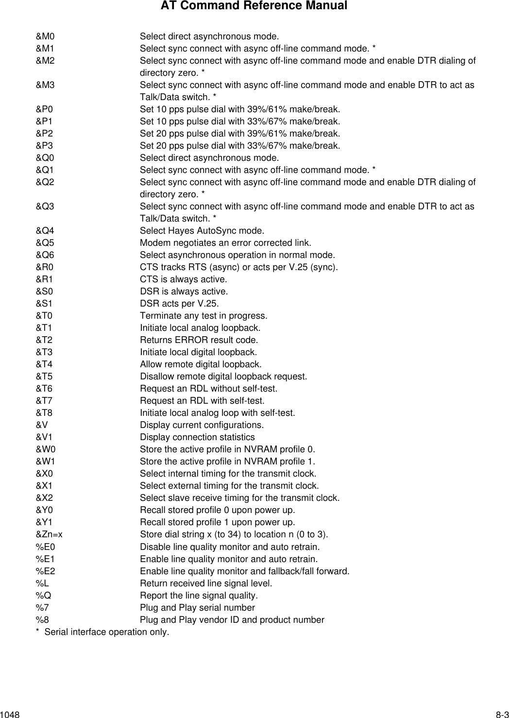
![AT Command Reference Manual1048 3-25Voice and Data = Blank for Data mode only.“SVD” for AudioSpan analog simultaneous audio/voice and data.“DSVD” for G.729A or DigiTalk digital simultaneous voice and data.3.2.6 AT+ Commands+MS - Select ModulationThis extended-format command selects the modulation and, optionally, enables or disables automode, specifies the lowestand highest connection rates, selects µ-Law or A-Law codec type, and enables or disables robbed bit signaling generation(server modem) or detection (client modem) using one to five subparameters. The command format is:+MS= <mod> [,[<automode>][,[<min_rate>][,[<max_rate>][,[<x_law>][,[< rb_signaling>]]]]]]<CR>Notes:1. For 14400 bps and lower speeds, the Nn command and S37 register can alternatively be used, in which case the +MSsubparameters will modified to reflect the Nn and S37=x settings. Use of the Nn and S37=x commands is notrecommended but is provided for compatibility with existing communication software. (S37 is not updated by the +MScommand.)2. Subparameters not entered (enter a comma only or <CR> to skip the last subparameter) remain at their current values.Reporting Selected OptionsThe modem can send a string of information to the DTE consisting of selected options using the following command:+MS?The response is:+MS: <mod>,<automode>,<min_rate>,<max_rate>,<x_law>,<rb_signaling>For example,+MS: 56,1,300,56000,0,0 [RC56 default values]+MS: 11,1,300,33600,0,0 [RC336 default values]+MS: 10,1,300,14400,0,0 [RC144 default values]Reporting Supported OptionsThe modem can send a string of information to the DTE consisting of supported options using the following command:+MS=?The response is:+MS: (list of supported <mod> values), (list of supported <automode> values),(list of supported <min_rate> values),(list of supported <max_rate> values), (list of supported <x_law> values), (list of supported <rb_signaling> values)For example,+MS: (0,1,2,3,9,10,11,56, 64,69),(0,1),(300-33600),(300-56000),(0,1),(0,1) [RC56]+MS: (0,1,2,3,9,10,11,64,69),(0,1),(300-33600),(300-33600),(0,1),(0,1) [RC336]+MS: (0,1,2,3,9,10,64,69),(0,1),(300-14400),(300-14400),(0,1),(0,1) [RC144]](https://usermanual.wiki/Itron/921.Modem-User-Manual/User-Guide-100350-Page-43.png)
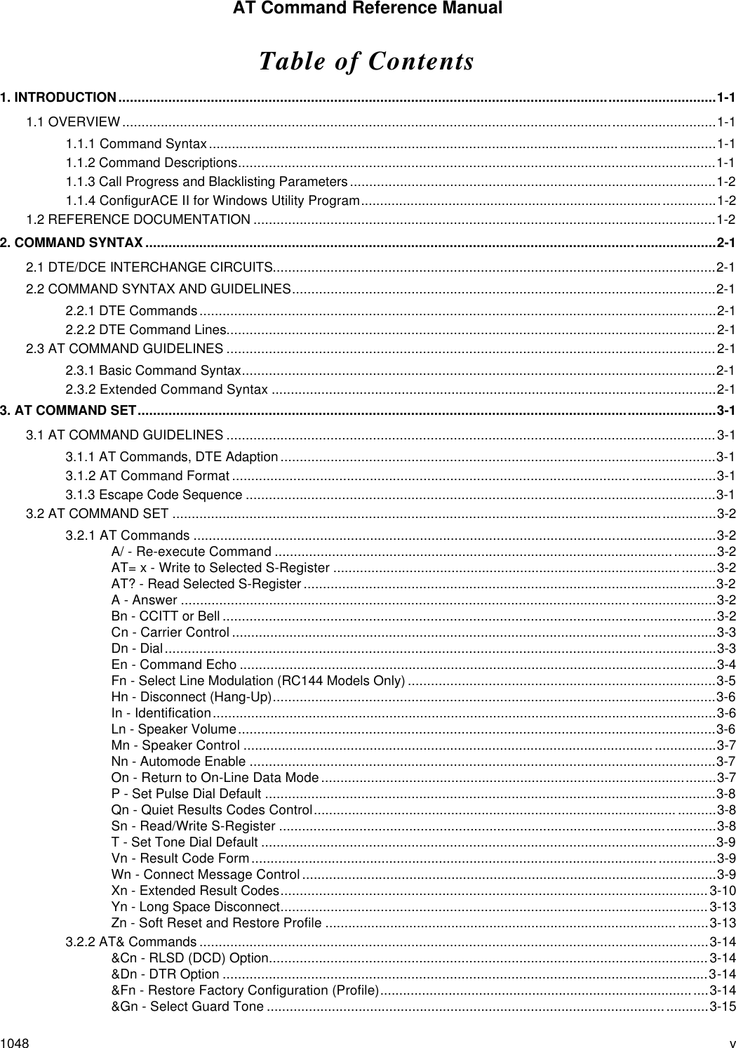
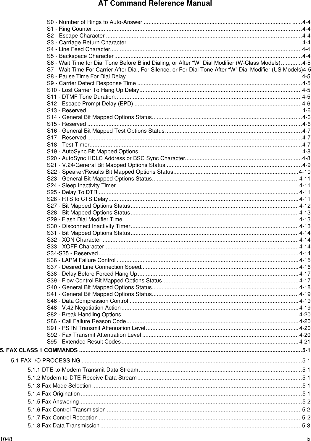
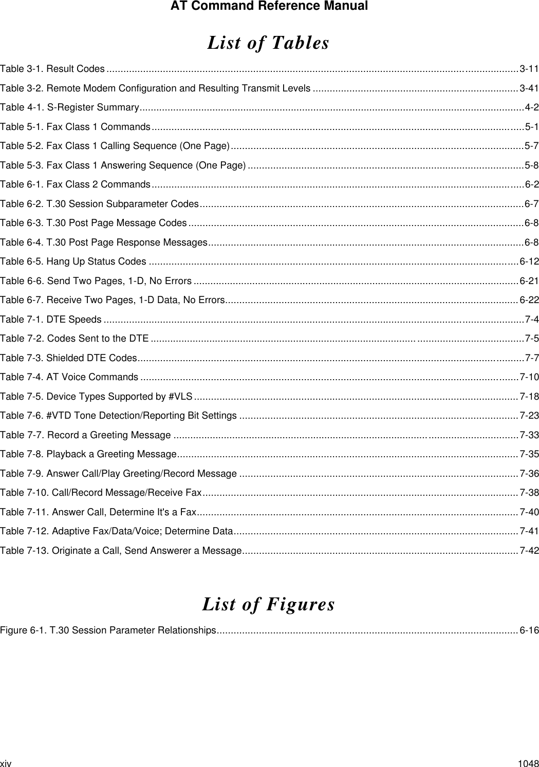
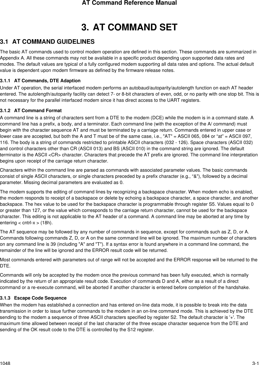
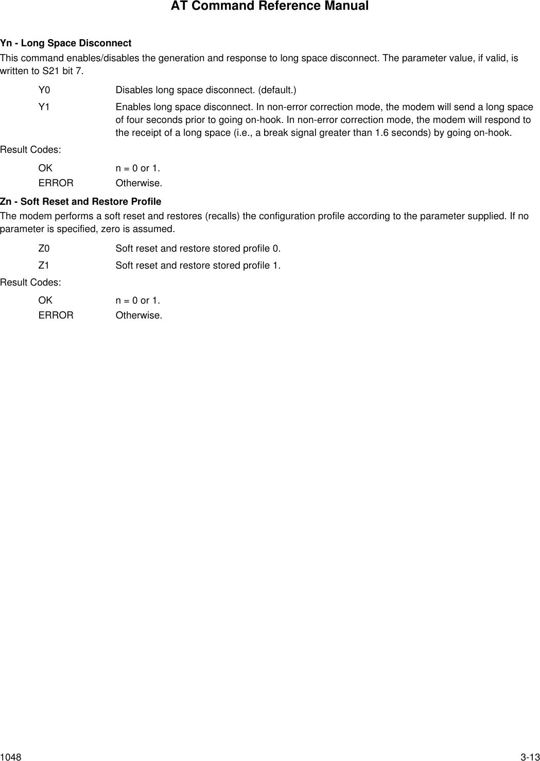
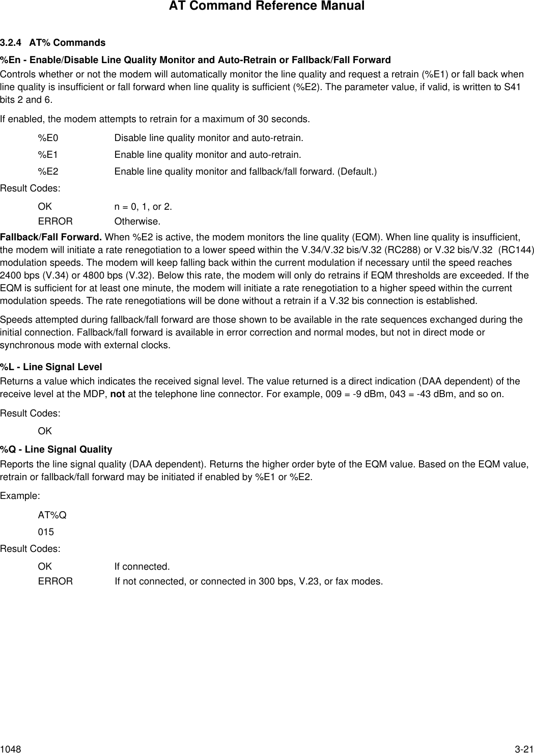
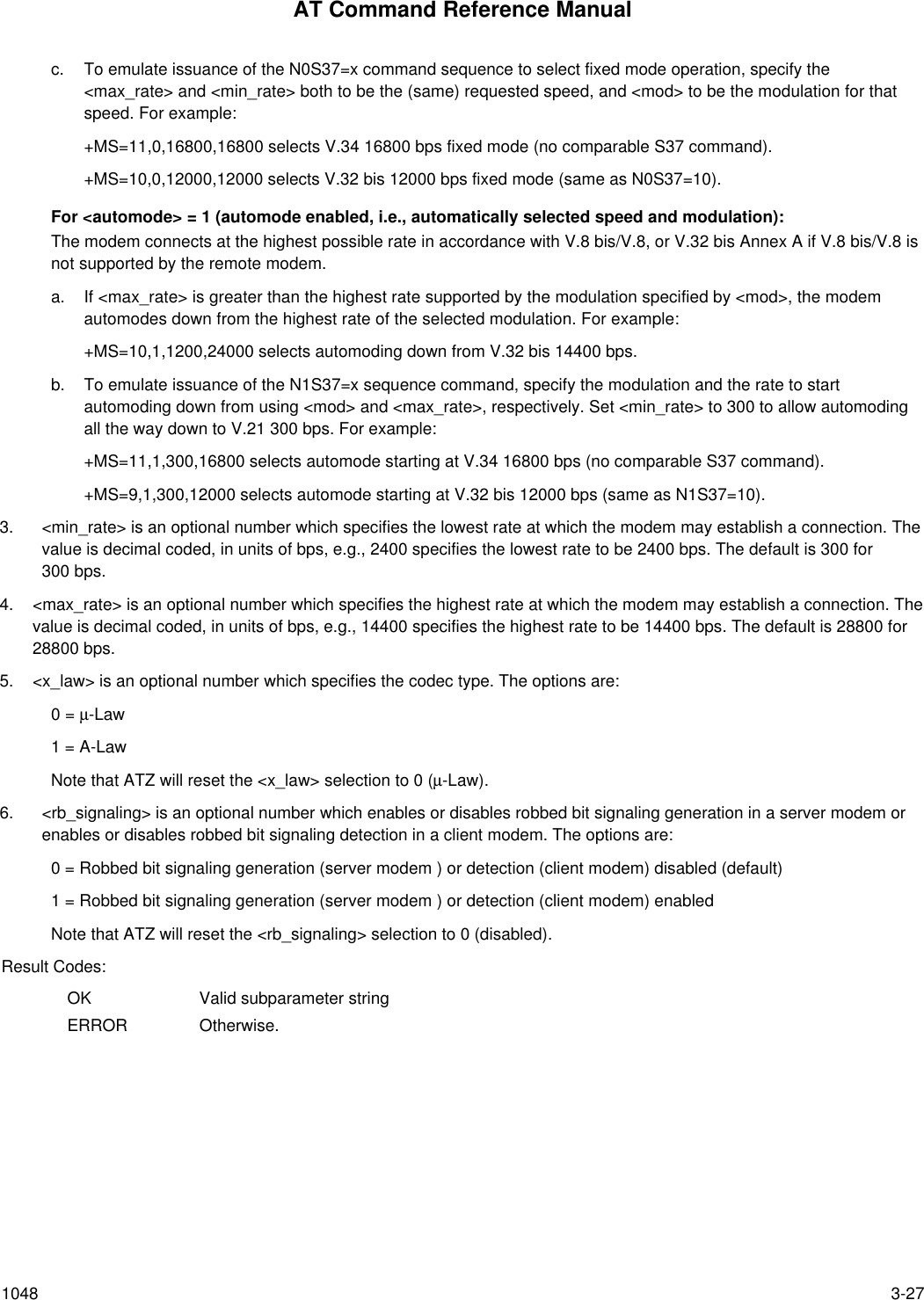
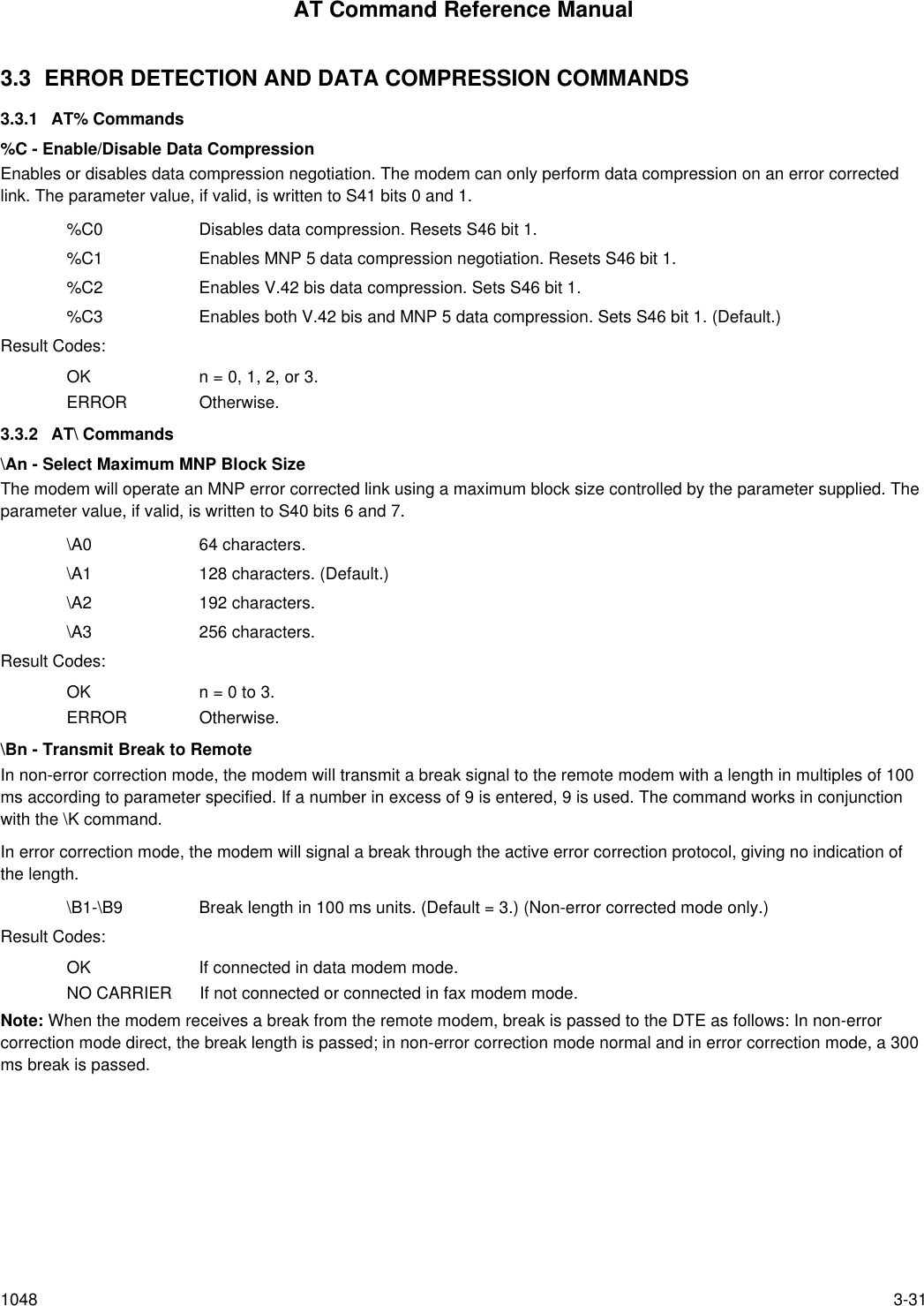
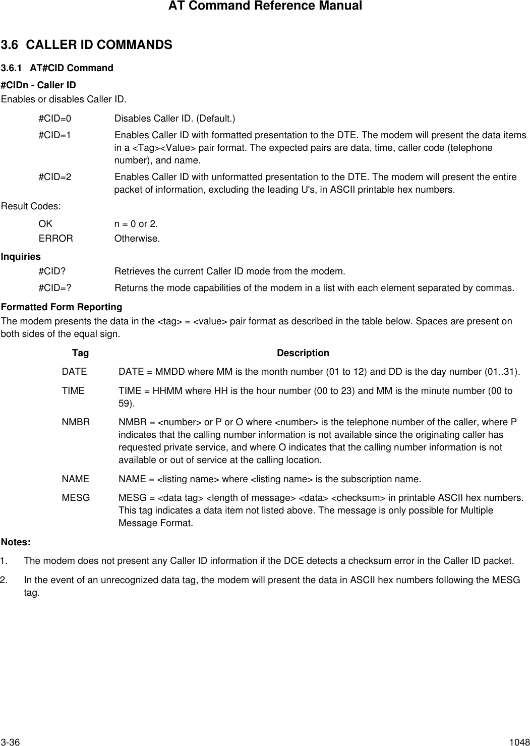
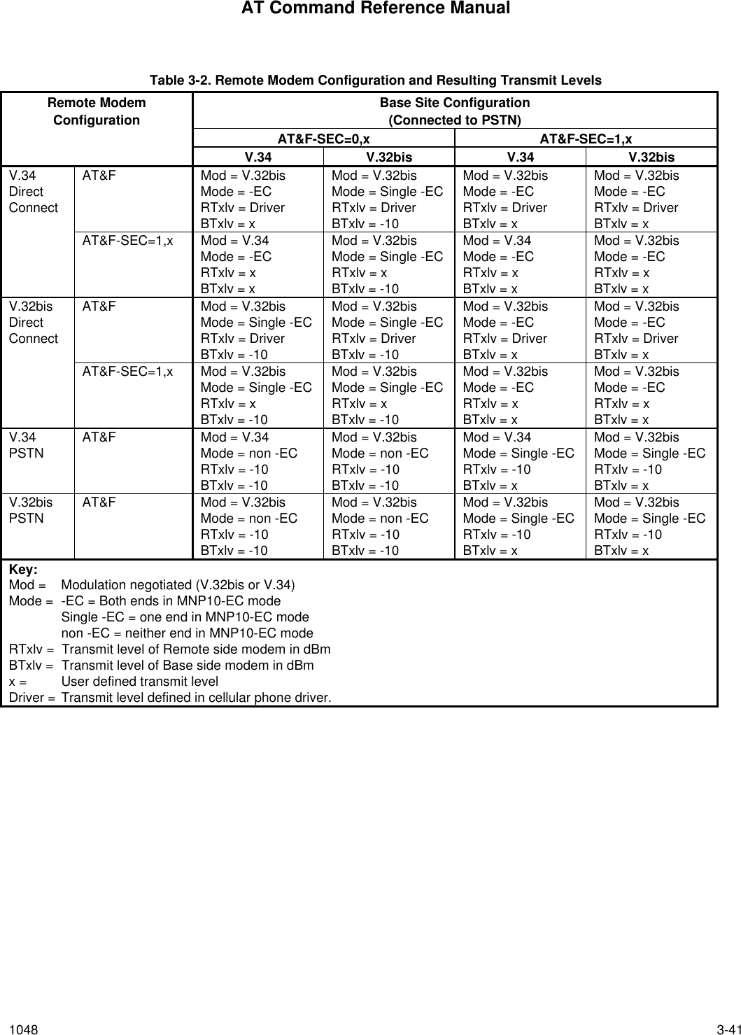
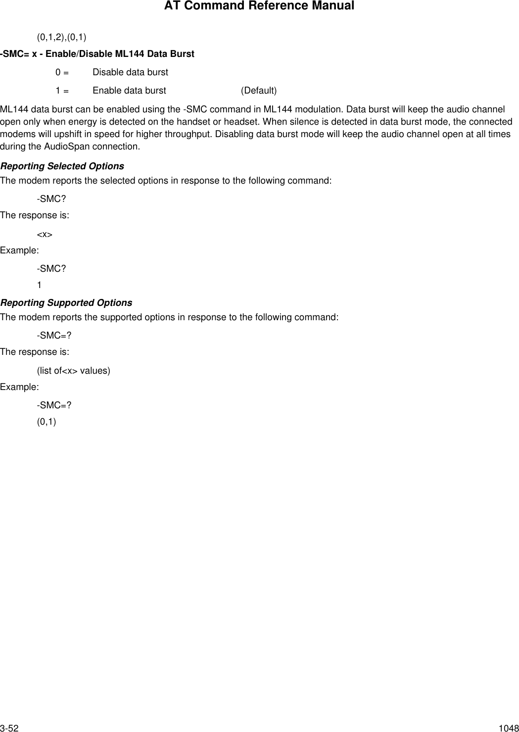
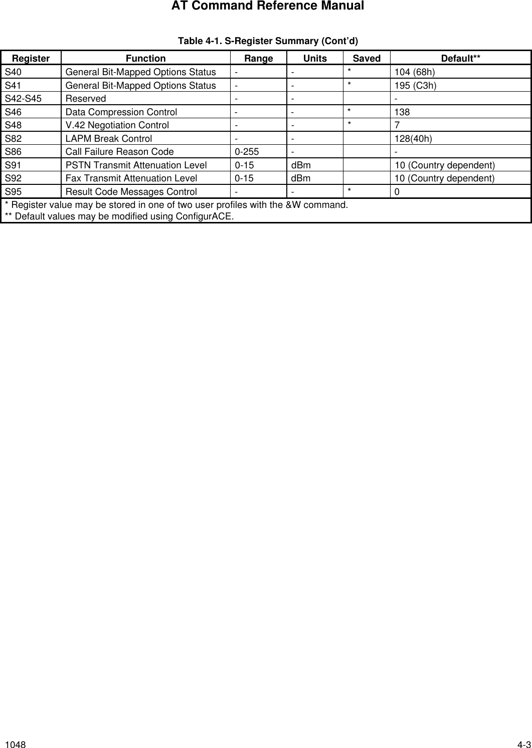
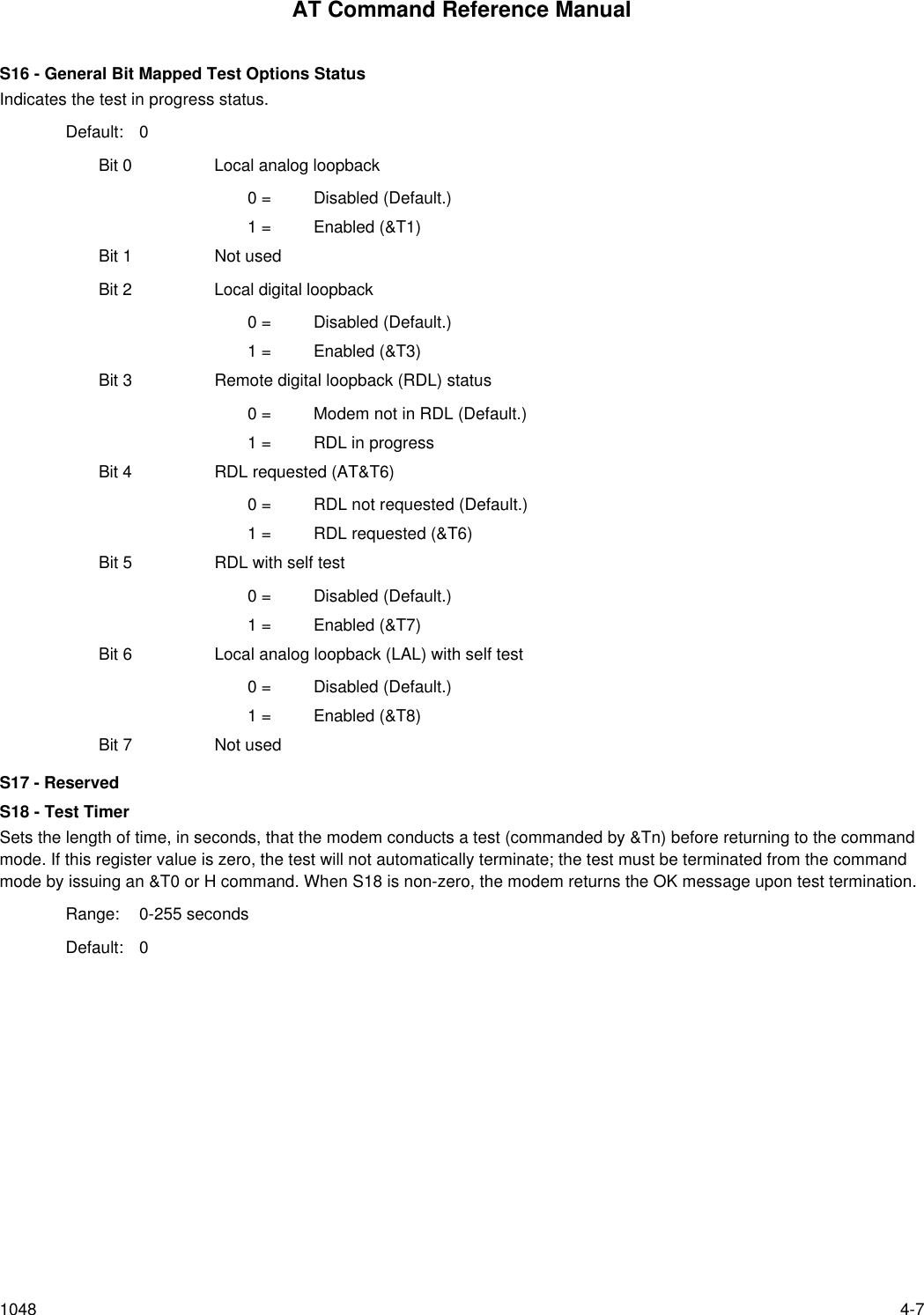
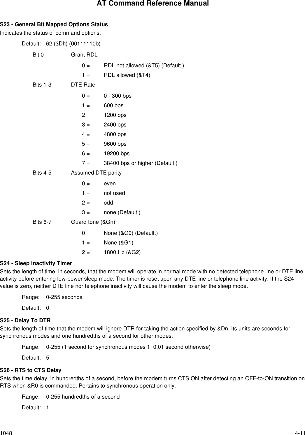
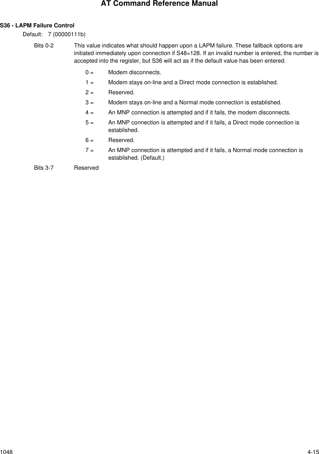
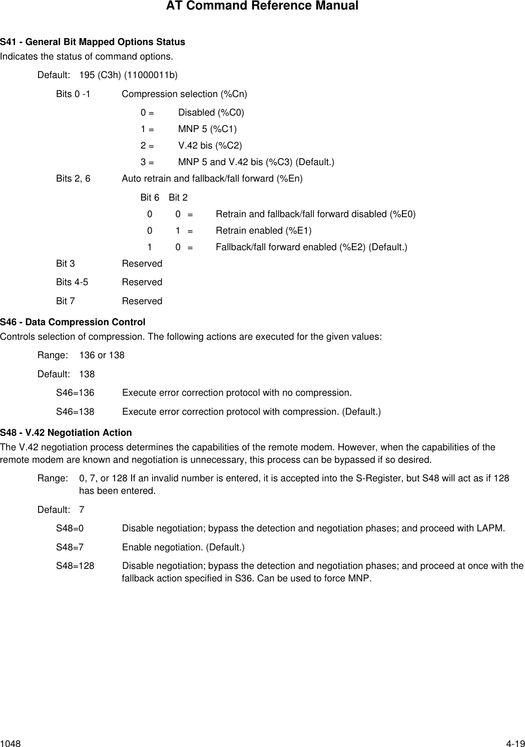
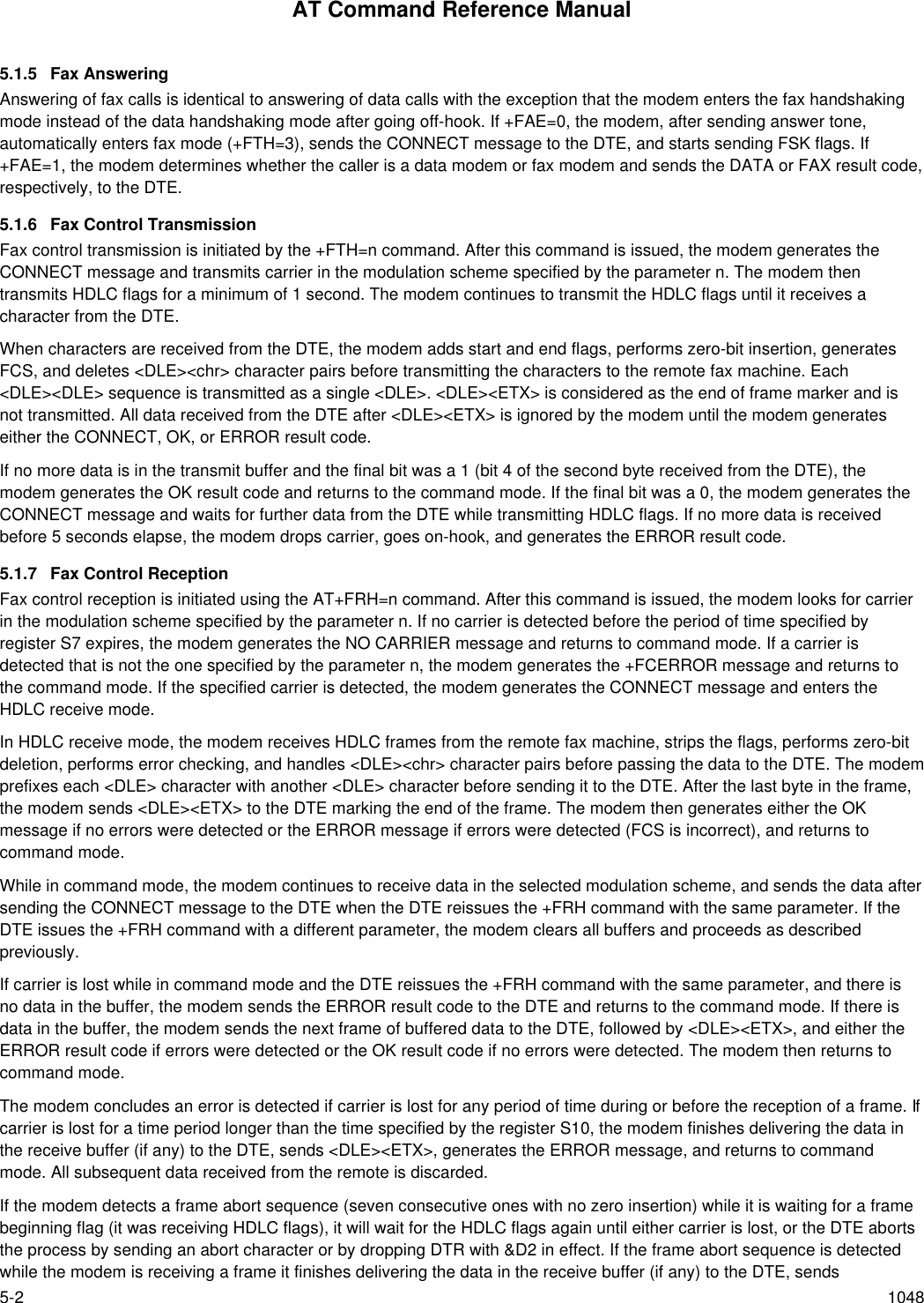
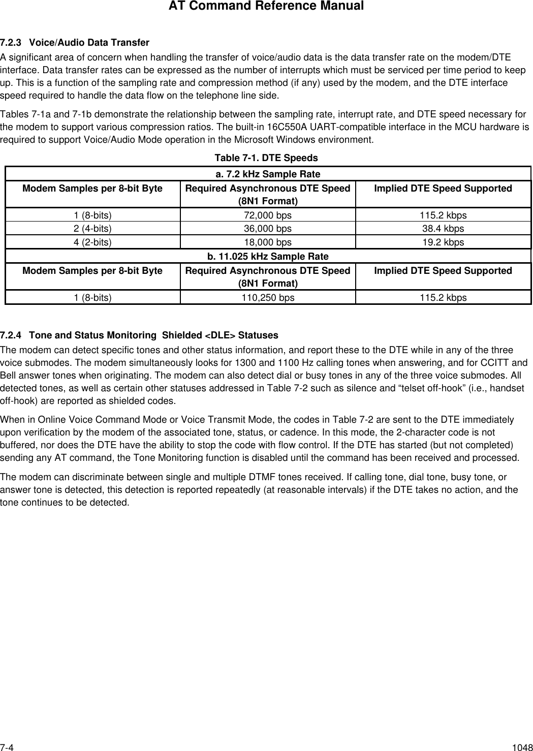
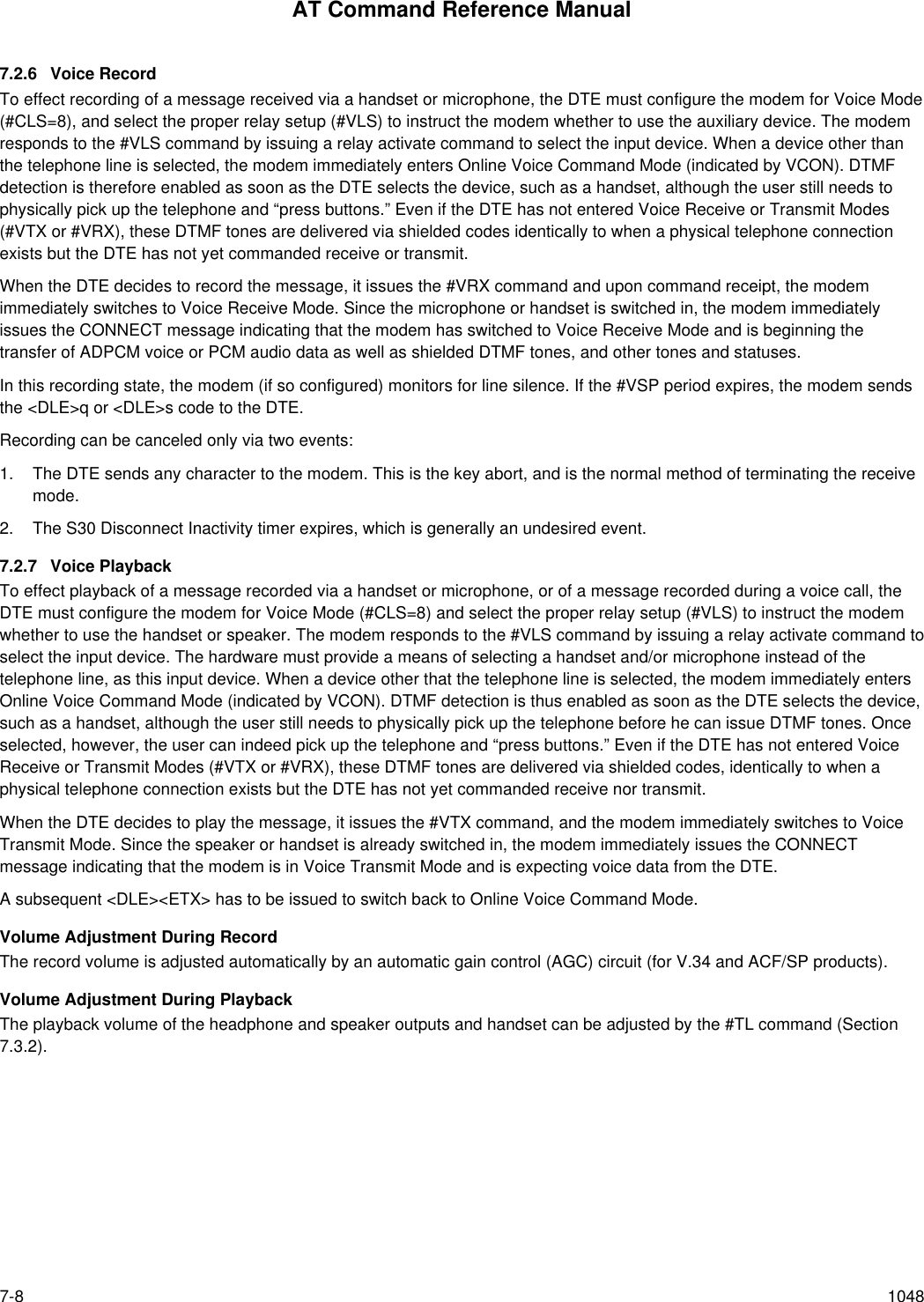
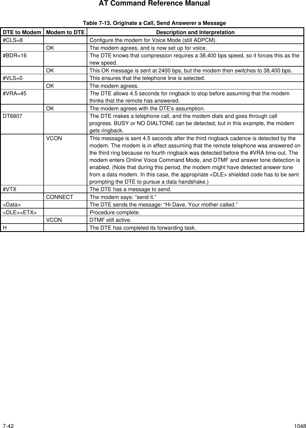
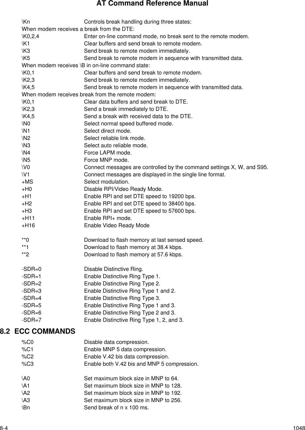
![AT Command Reference Manual3-26 1048Subparameter Definitions1. <mod> = A decimal number which specifies the preferred modulation (automode enabled) or the modulation (automodedisabled) to use in originating or answering a connection. The options are:<mod> Modulation Possible Rates (bps) 1Notes0V.21 3001V.22 12002V.22 bis 2400 or 12003V.23 1200 See Note 29V.32 9600 or 480010 V.32 bis 14400, 12000, 9600, 7200, or 4800 Default for RC14411 V.34 33600, 31200, 28800, 26400, 24000, 21600,19200, 16800, 14400, 12000, 9600, 7200, 4800, or2400Default for RC56/RC336/RC288[RC56/RC336/RC288 only]56 K56flex 56000, 54000, 52000, 50000, 48000, 46000,44000, 42000, 40000, 38000, 36000, 34000, 32000 [RC56 only]64 Bell 103 30069 Bell 212 1200Notes:1. See optional <automode>, <min_rate>, and <max_rate> subparameters.2. For V.23, originating modes transmit at 75 bps and receive at 1200 bps; answering modes transmit at 1200 bpsand receive at 75 bps. The rate is always specified as 1200 bps.The modem may also automatically switch to another modulation (automode), subject to the following constraints:a. The modem may not be able to automatically switch from the current modulation (specified by <mod>) to someother modulation. For example, there is no standard way to automode from Bell 103 to V.23.b. The DTE may disable automode operation (see <automode> below).c. The DTE may constrain the range of modulations available by specifying the lowest and highest rates (see<min_rate> and <max_rate> below).2. <automode> is an optional numeric value which enables or disables automatic modulation negotiation using V.8 bis/V.8or V.32 bis Annex A. The options are:<automode> Option Selected Notes0Automode disabled1Automode enabled using V.8 bis/V.8 or V.32 Annex A DefaultThe default value is 1, which enables automode. Note, however, there are modulations for which there is no automaticnegotiation, e.g., Bell 212 (<mod> = 69).For <automode> = 0 (automode disabled, i.e., fixed modulation):a. If <max_rate> is within the rates supported by the selected modulation, the selected rate is that specified by<max_rate>. For example:+MS=10,0,1200,4800 selects V.32 bis 4800 bps fixed rate.b. If <max_rate> is greater than the highest speed supported by the modulation specified by <mod>, the startingrate is the highest rate supported by the selected modulation. For example:+MS=10,0,2400,14400 selects V.32 bis 14400, 12000, 9600, 7200, or 4800 bps.](https://usermanual.wiki/Itron/921.Modem-User-Manual/User-Guide-100350-Page-44.png)
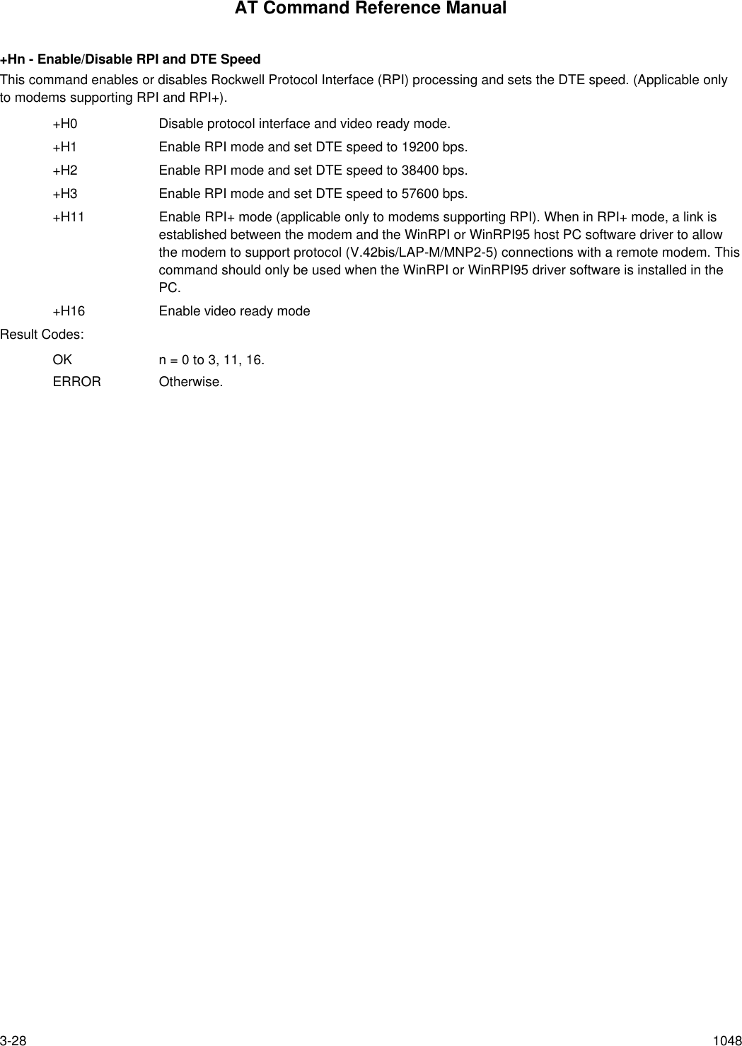
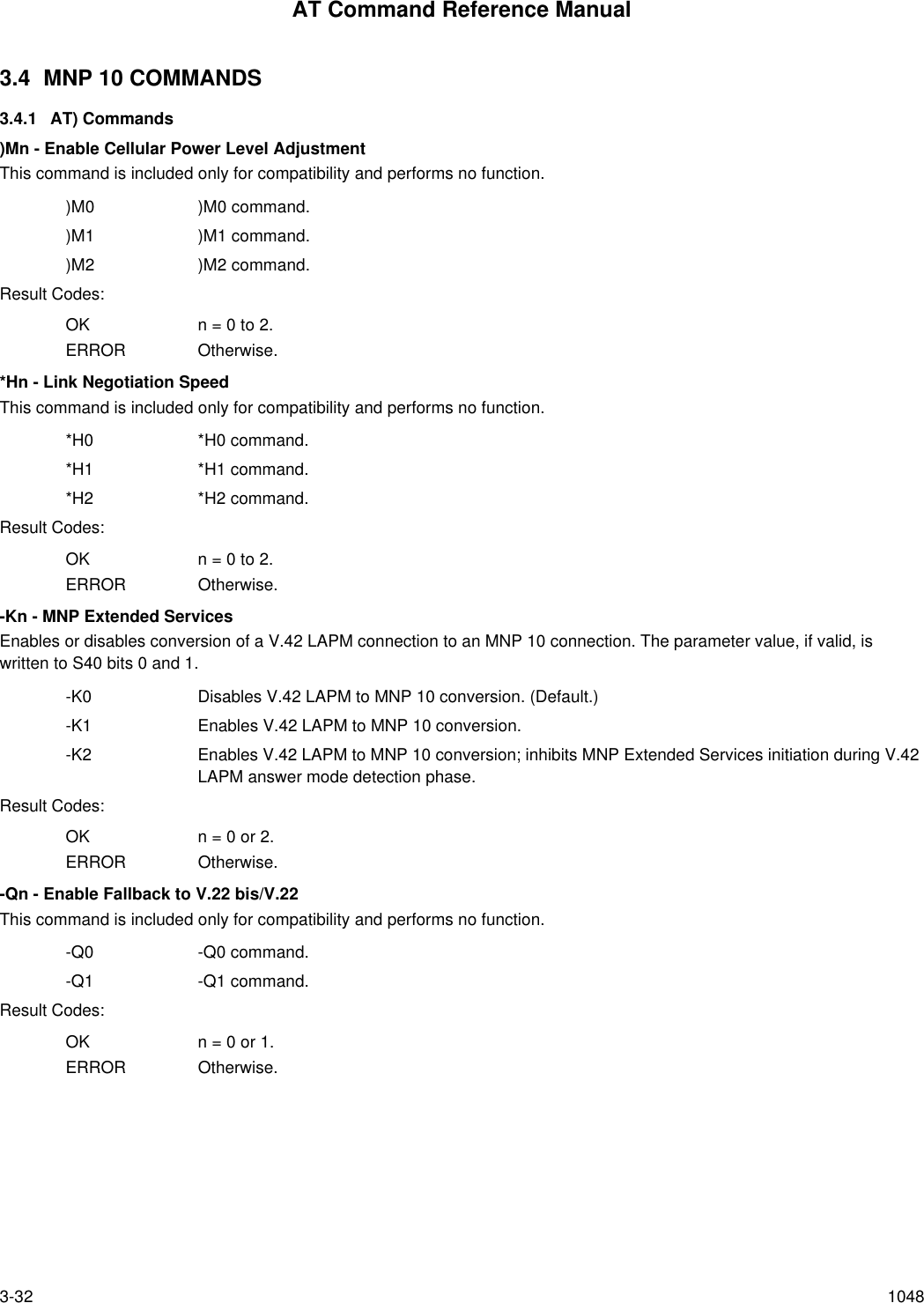
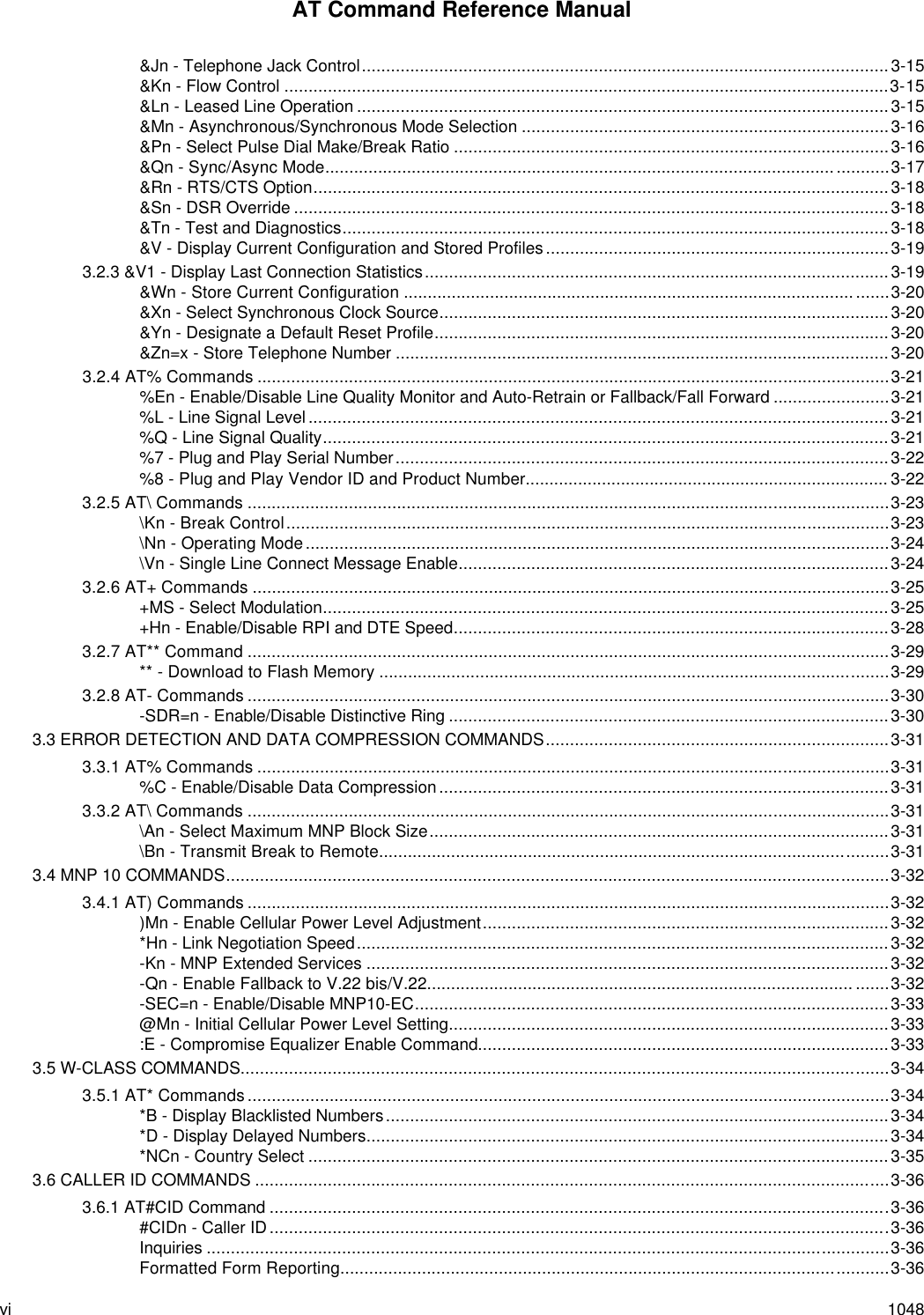
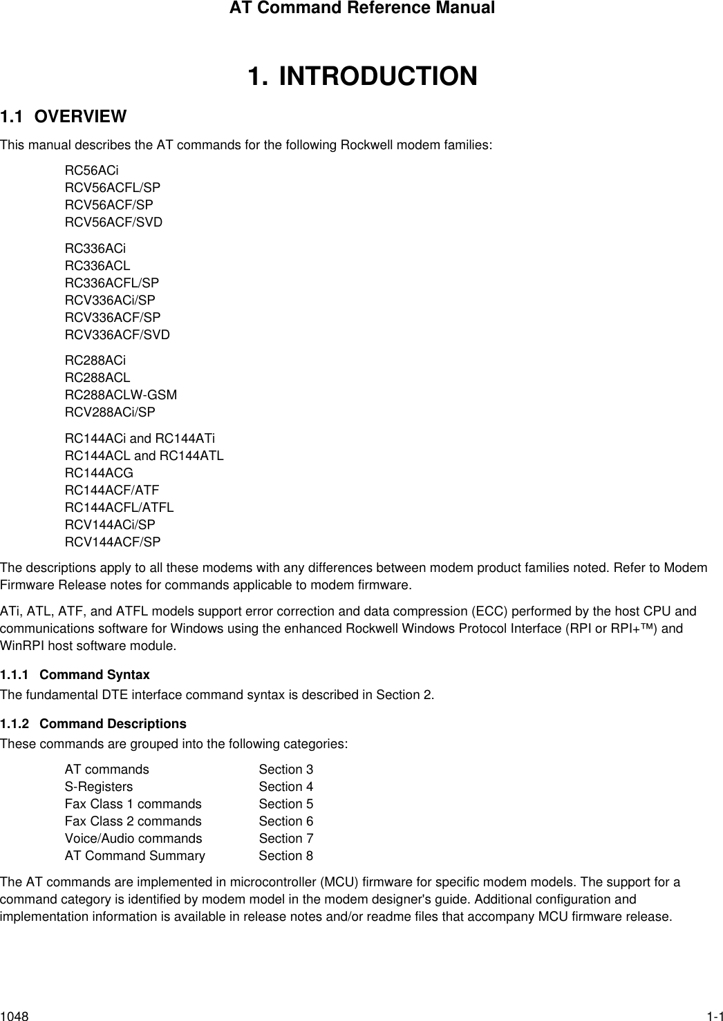
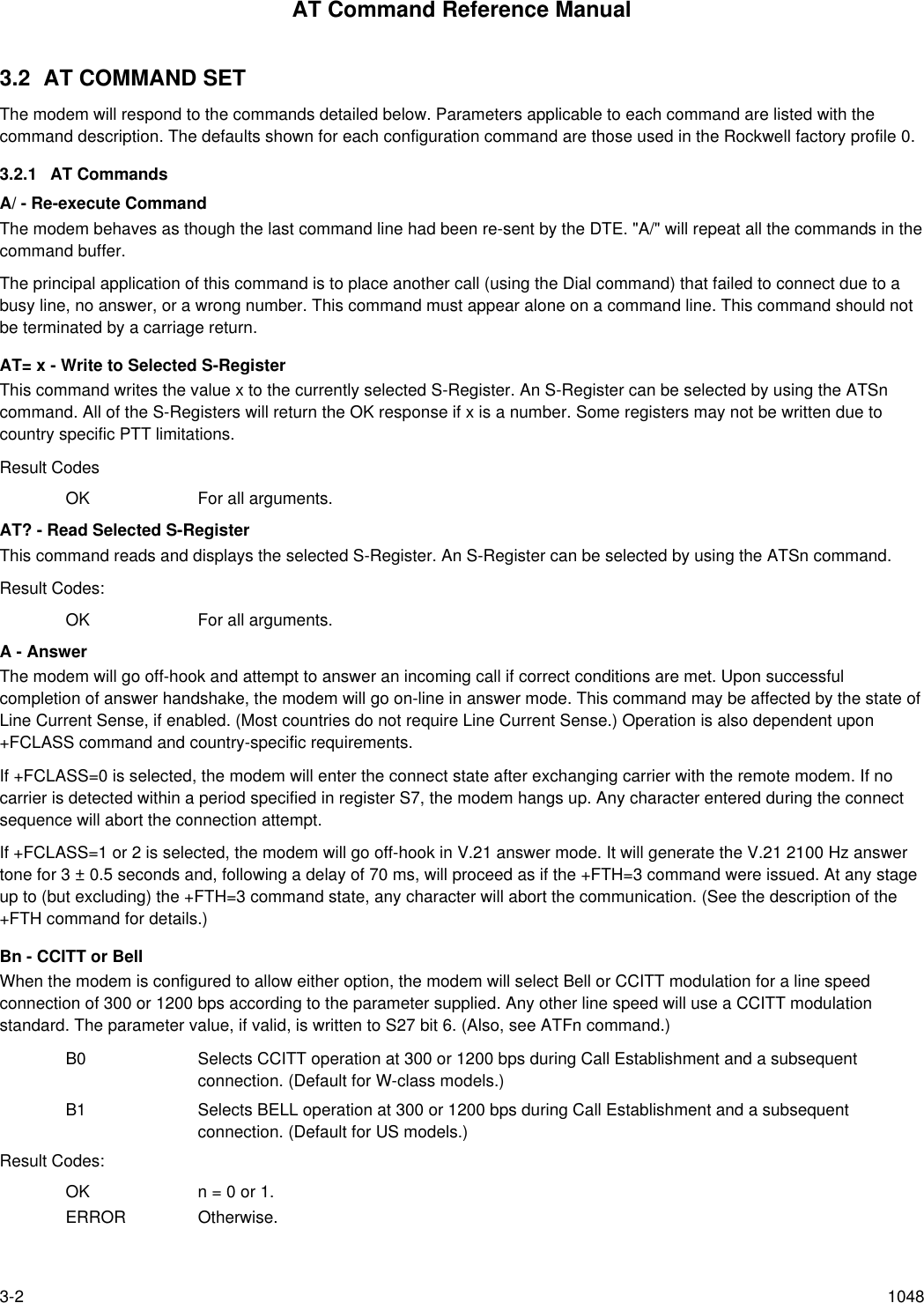
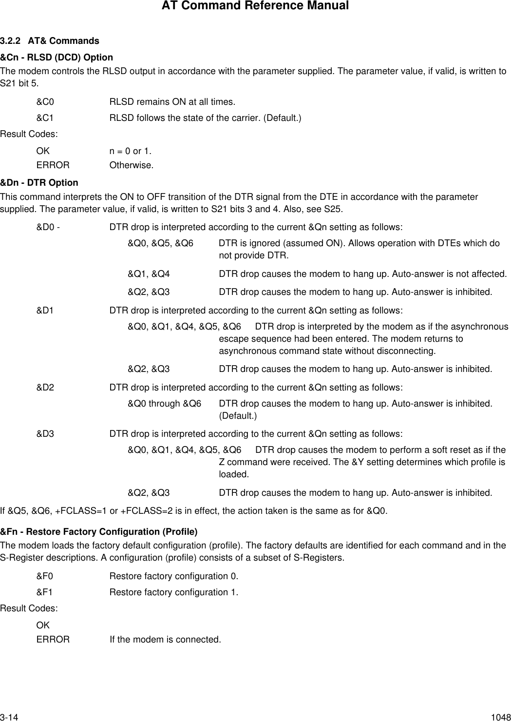
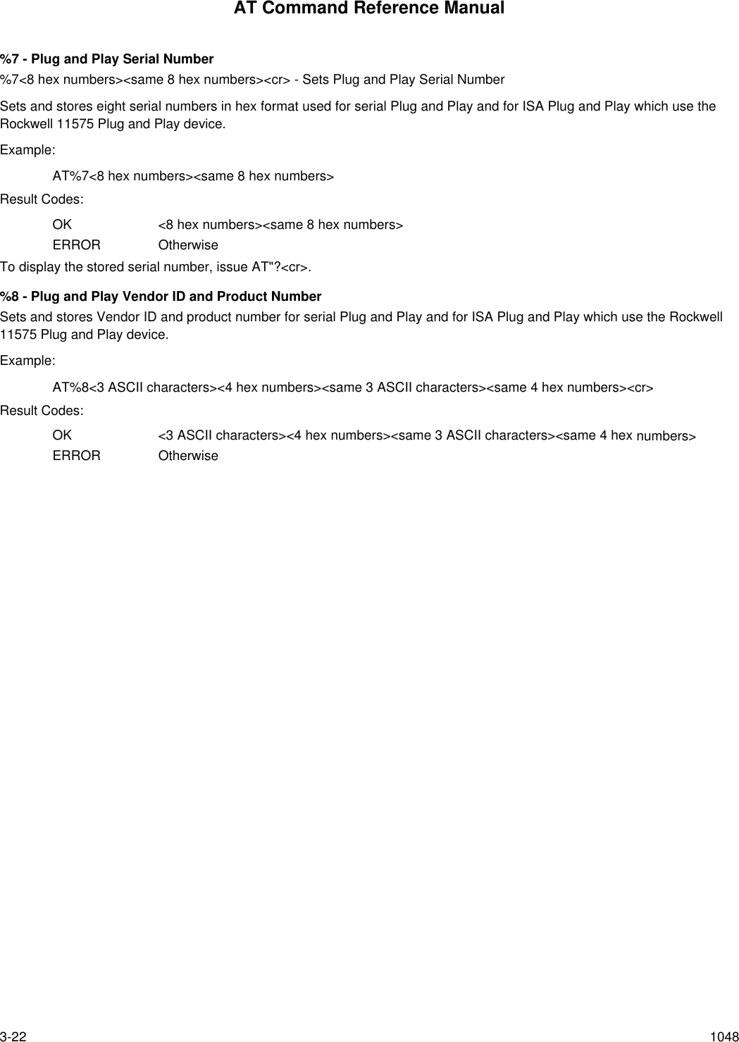
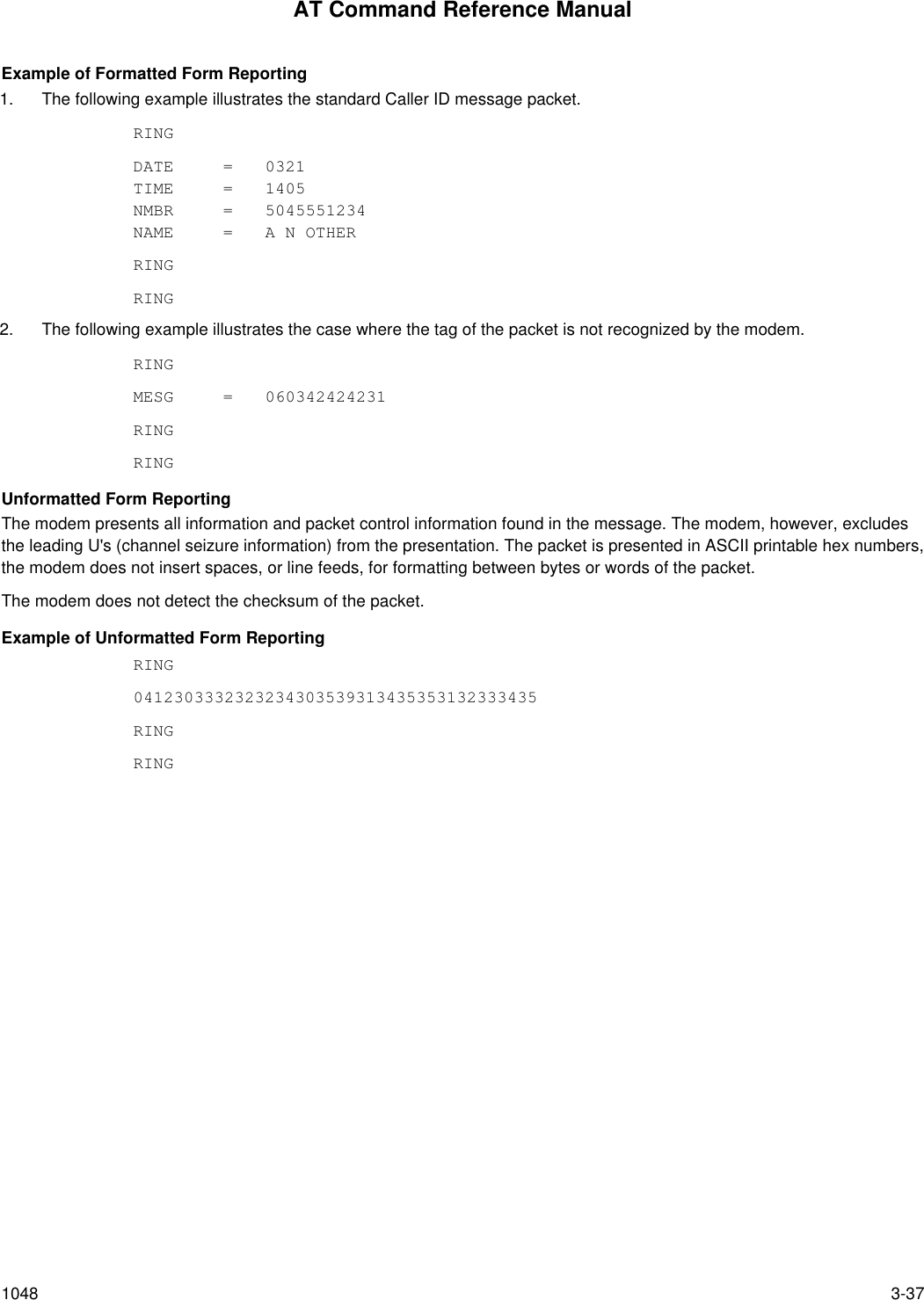
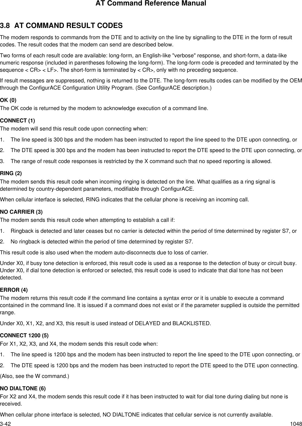
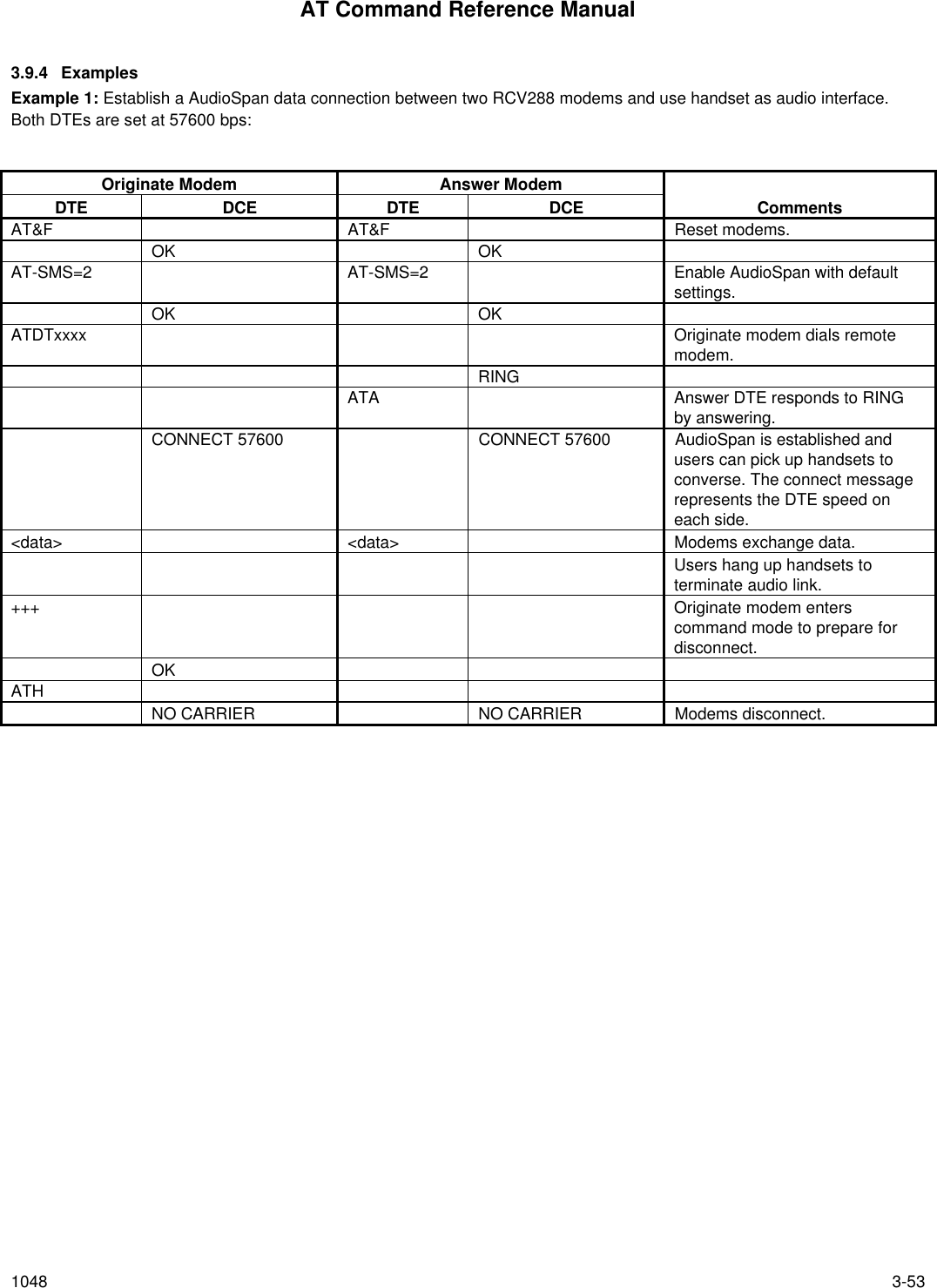
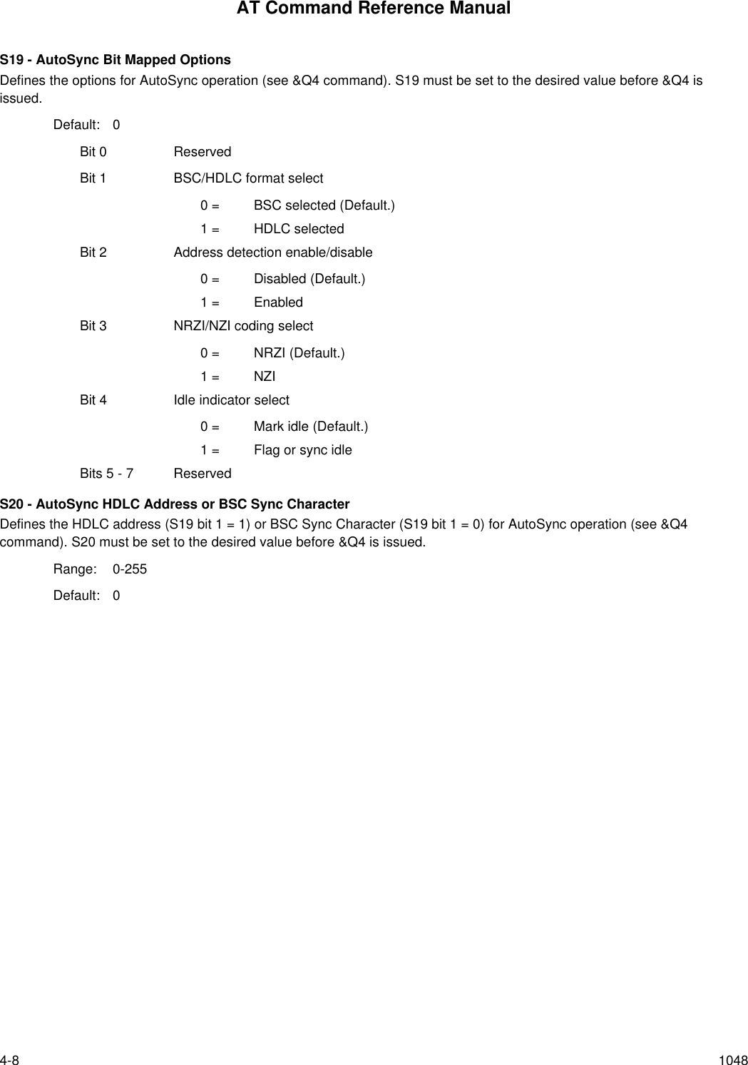
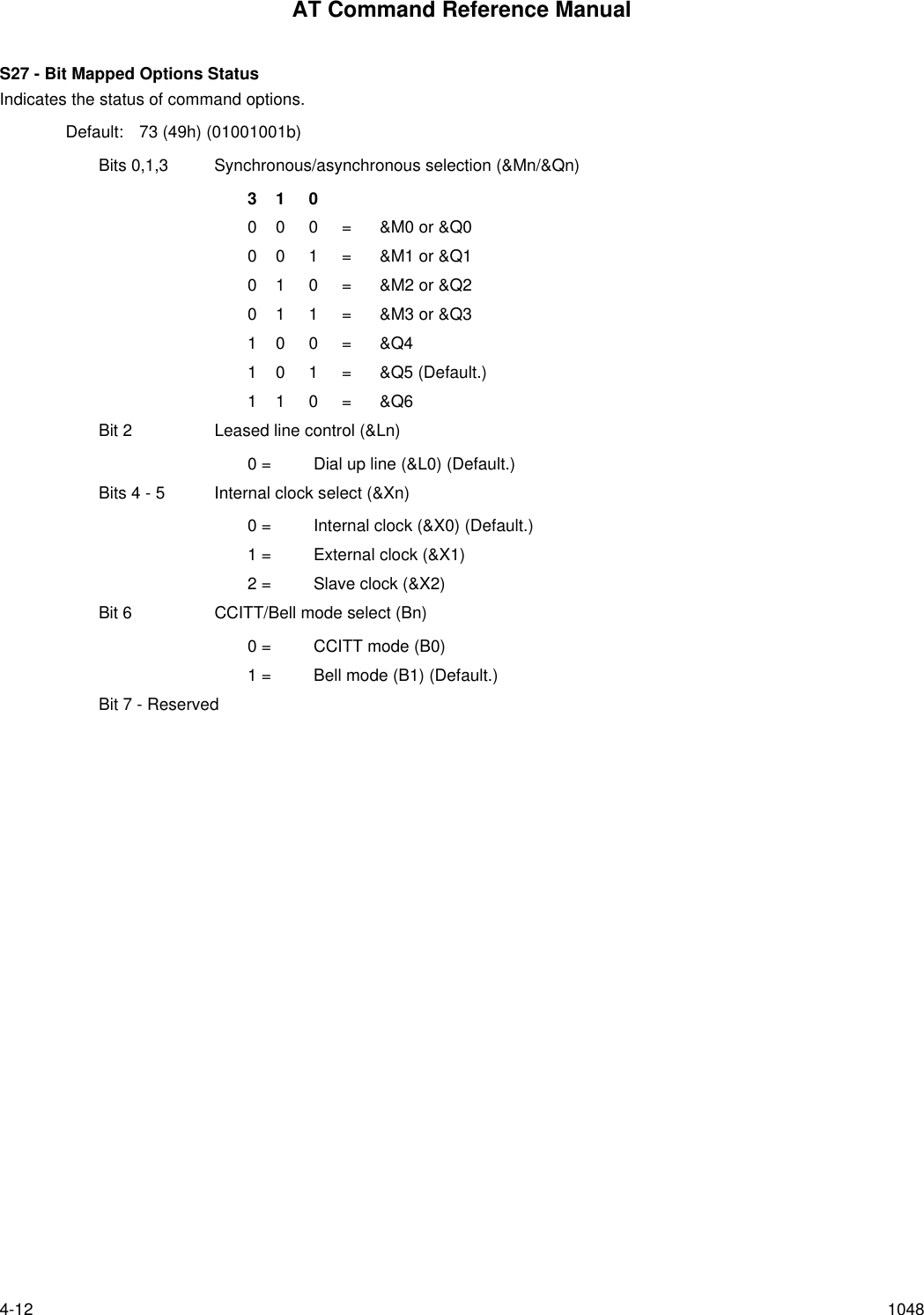
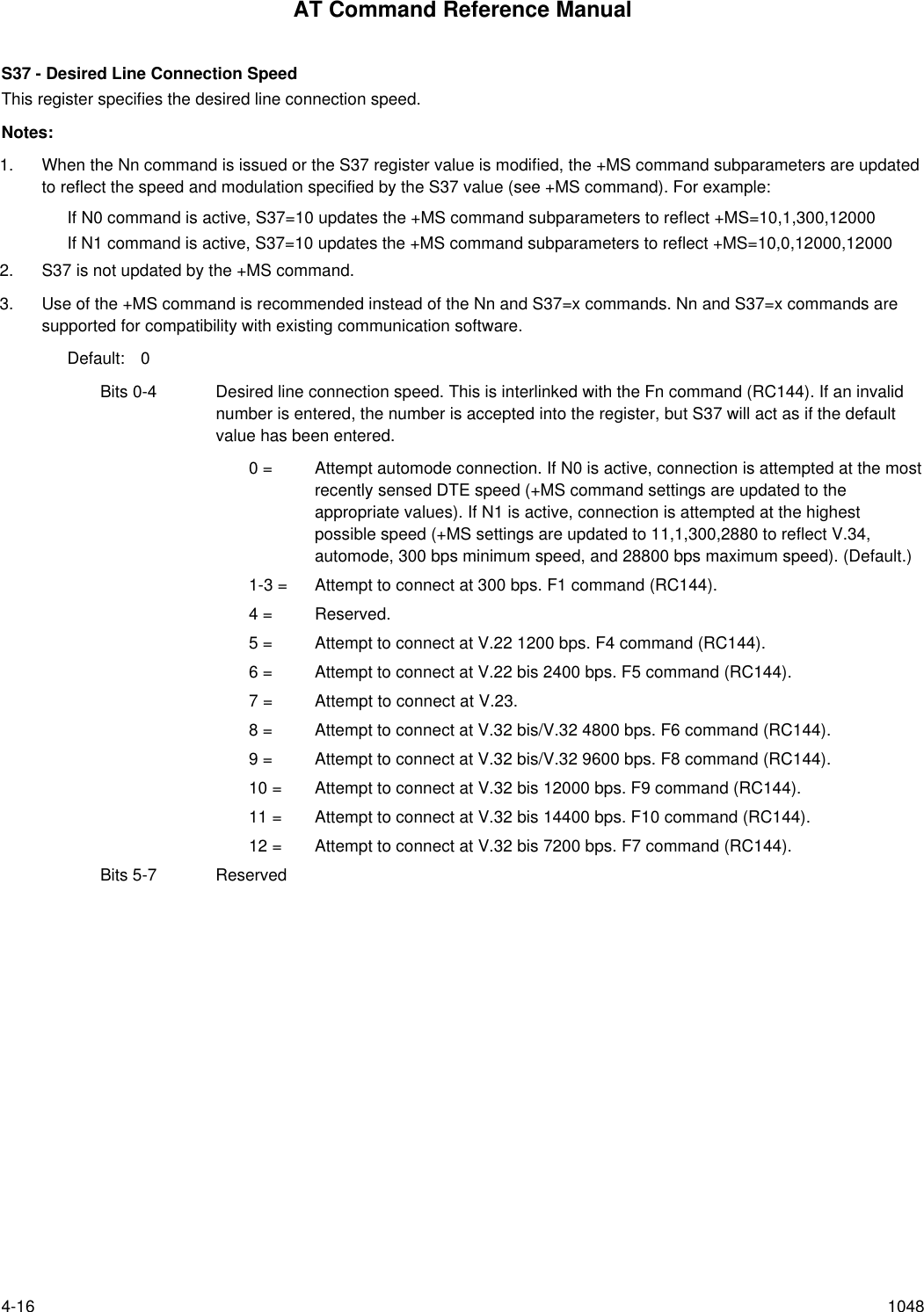
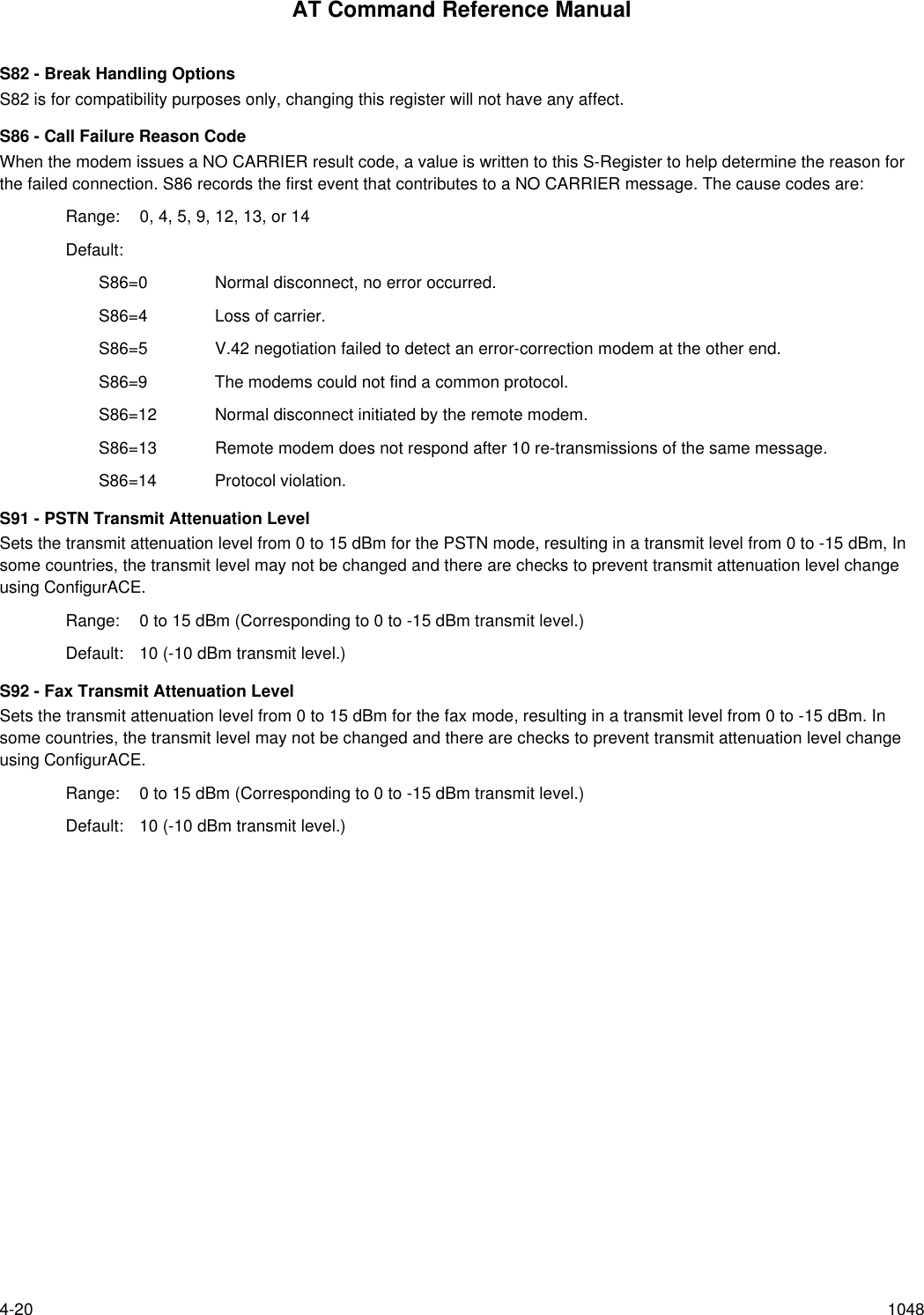
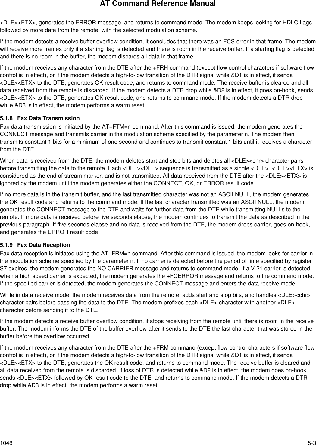
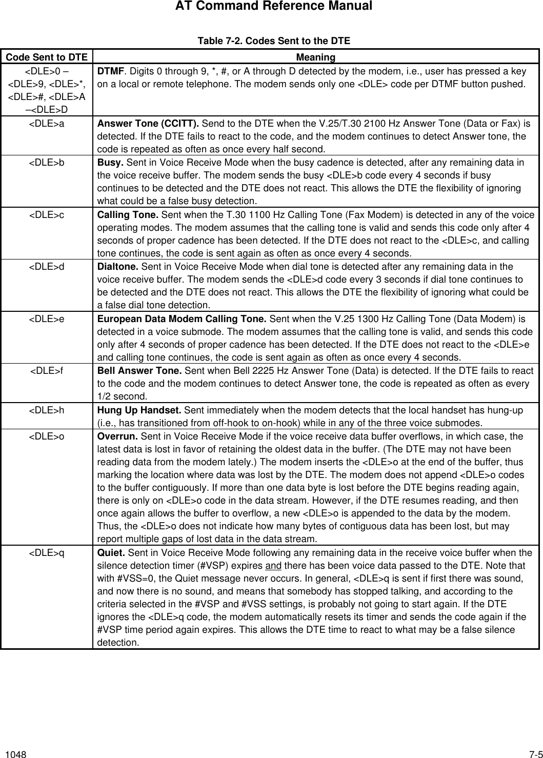
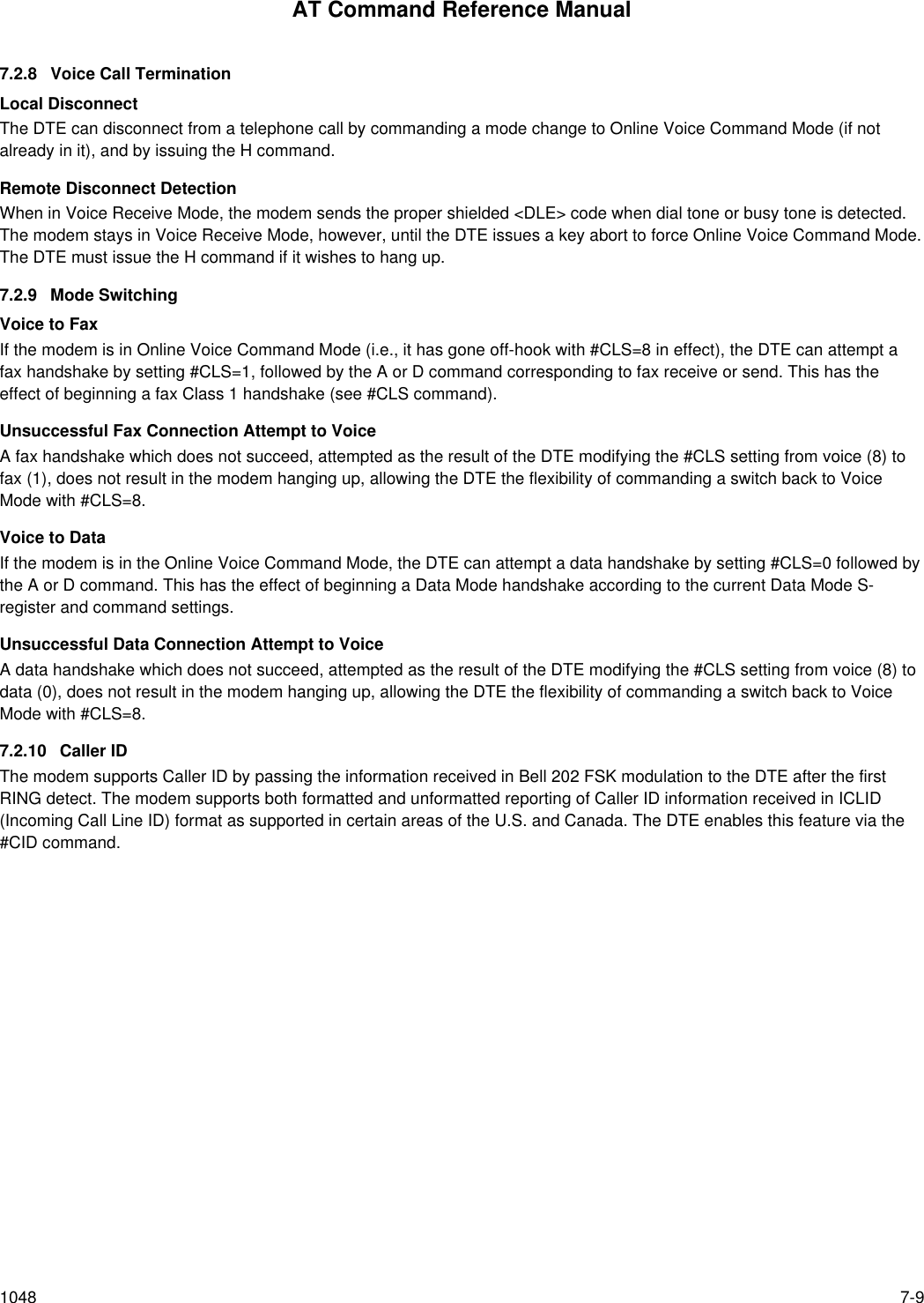
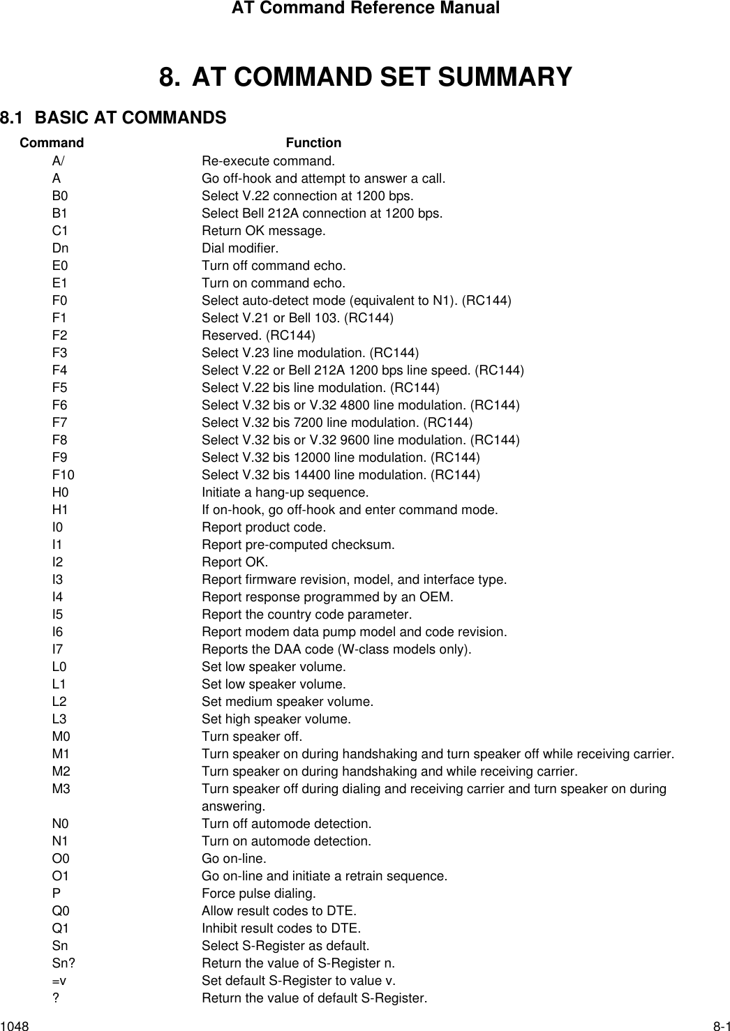
![AT Command Reference Manual1048 3-33-SEC=n - Enable/Disable MNP10-ECEnables or disables MNP10-EC operation. The command format is:-SEC=n,[<tx level>] where <tx level> is the optional transmit level sub parameter.-SEC=0 Disable MNP10-EC; the transmit level is that defined in S91.-SEC=1,[<tx level>] Enable MNP10-EC; the transmit level will be defined by the sub parameter <tx level>range 0 to 30 (0 dBm to -30 dBm), the default <tx level> (<tx level> not specified) is theS91 value.Result Codes:OK n=0, 1, or 1 and <tx level>=0 to 30ERROR OtherwiseExample: AT-SEC=1,18 enables MNP10-EC and sets the transmit level to -18 dBm.Note: If AT-SEC=0, the modem will automatically set AT-SEC=1 if the remote modem indicates Cellular in the V.8 bis/V.8phase or if a Cellular Driver is loaded and the Cell Phone is attached.InquiriesAT-SEC? Retrieves the current -SEC command settings, e.g., 1,18.@Mn - Initial Cellular Power Level SettingThis command is included only for compatibility and performs no function.@M0 @M0 command....@M30 @M30 command.Result Codes:OK n = 0 to 30.ERROR Otherwise.:E - Compromise Equalizer Enable CommandThis command is included only for compatibility and performs no function.:E0 :E0 command.:E1 :E1 command.Result Codes:OK n = 0 or 1.ERROR Otherwise.](https://usermanual.wiki/Itron/921.Modem-User-Manual/User-Guide-100350-Page-51.png)
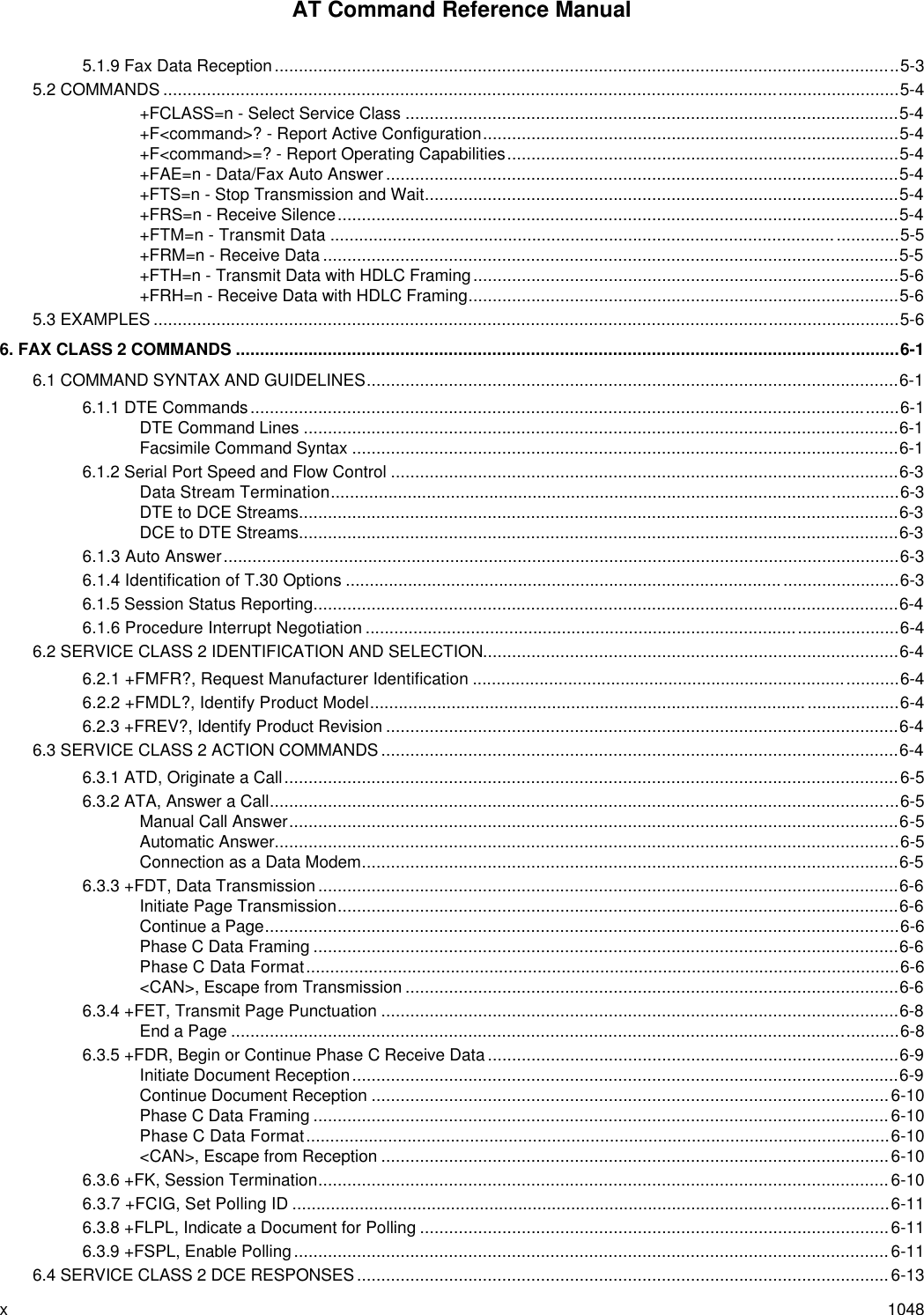
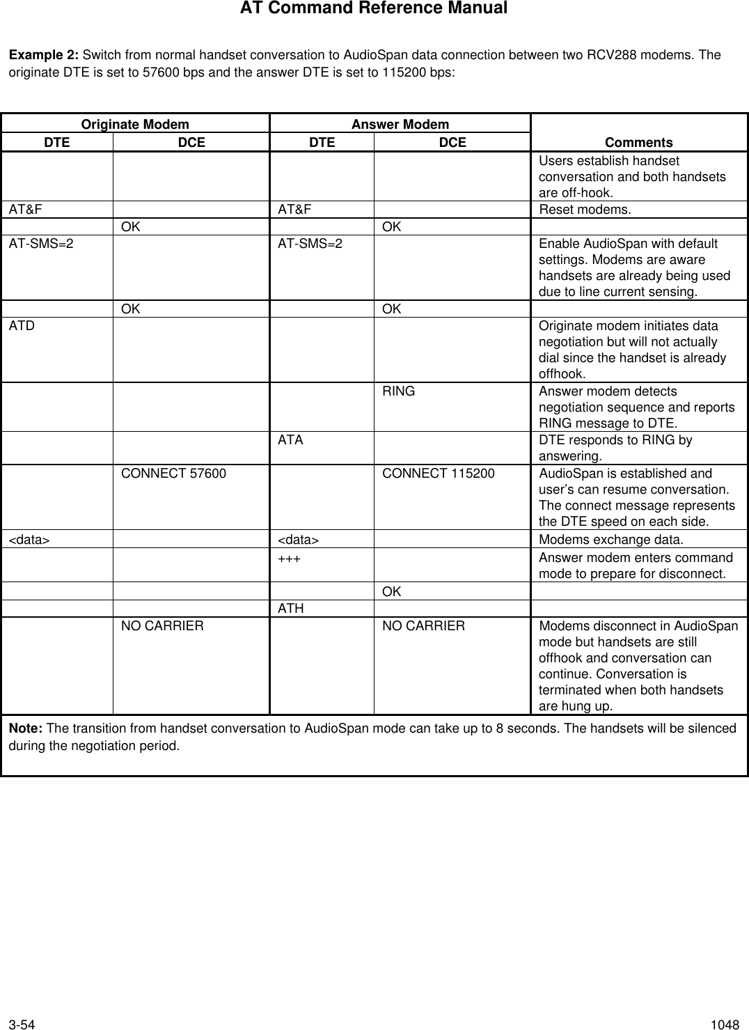
![AT Command Reference Manual3-38 10483.7 CELLULAR COMMANDSThe Direct Connect Modem allows a direct interface to most cellular telephones eliminating the need for other intelligentinterfaces.Landline modems operate with the telephone system by either going off hook detecting dialtone and the dialing thetelephone number using pulses or DTMF digits, or detecting the RING signal and answering the call. Intelligent cellularphone interfaces connect between the modems RJ-11 socket and the cellular phone's data interface. The interface provideslandline features to the modem (line current, dial tone, ringing, etc.), and translates the modem's signals (off hook, DTMFdigits, etc.) into signals that the cellular phone understands. Once connected the interface acts as a transparent link betweenthe modem and the cellular telephone.The Direct Connect Modem interfaces directly to the cellular phone's data interface and provides direct control over thecellular phones operation. For example if the user were to instruct the modem to dial using the ATDTnnnn command themodem would relay the telephone number and the SEND command to the cellular phone over the data interface.The modem connects to the cellular phone using a special cable which must be purchased separately. A different cable isrequired for each cellular phone or make of cellular phones. Below is a block diagram of a typical Direct Connect CellularModem (based on AK14-X270 Rev 4 reference schematic).3.7.1 Cellular Phone DriversThe data interface to cellular phones differs between manufacturers and models and requires a unique cellular phone driverfor each phone or group of phones. Therefore the particular phone driver needs to be downloaded from the PC into themodem's RAM before the modem can be used directly with the cellular phone. If a driver is not loaded the modem willoperate as a normal landline modem.3.7.2 Cellular Commands^C2 - Download Cellular Phone DriverThe ^C2 command initiates the cellular phone driver download function. Upon receipt of the command, the modem issuesthe "OK" message. The user then performs an ASCII download of the driver (in .S37 format) from the host to the modem,typically using a communications software package (with transmit pacing turned off).^C2 Download Cellular Phone commandResult Codes:OK[Download Process]OK Cellular phone driver download completed successfullyERROR Cellular phone driver download not completed successfully, e.g., checksum of record (in S37 file)is not correct, driver size is larger than 2k bytes, or an invalid driver is downloaded, or modem isconnected.^I - Identify Cellular Phone DriverThe modem reports the identification of the loaded cellular phone driver in response to the ^I command. The response isdependent upon the driver.Result Codes (Typical):CELLULAR DRIVER: OKI 900/910(c) Copyright 1994, Spectrum Cellular, Inc.Version 0.07 Thu Jan 10:29:52 1994OKorERROR Cellular phone driver is not loaded](https://usermanual.wiki/Itron/921.Modem-User-Manual/User-Guide-100350-Page-56.png)
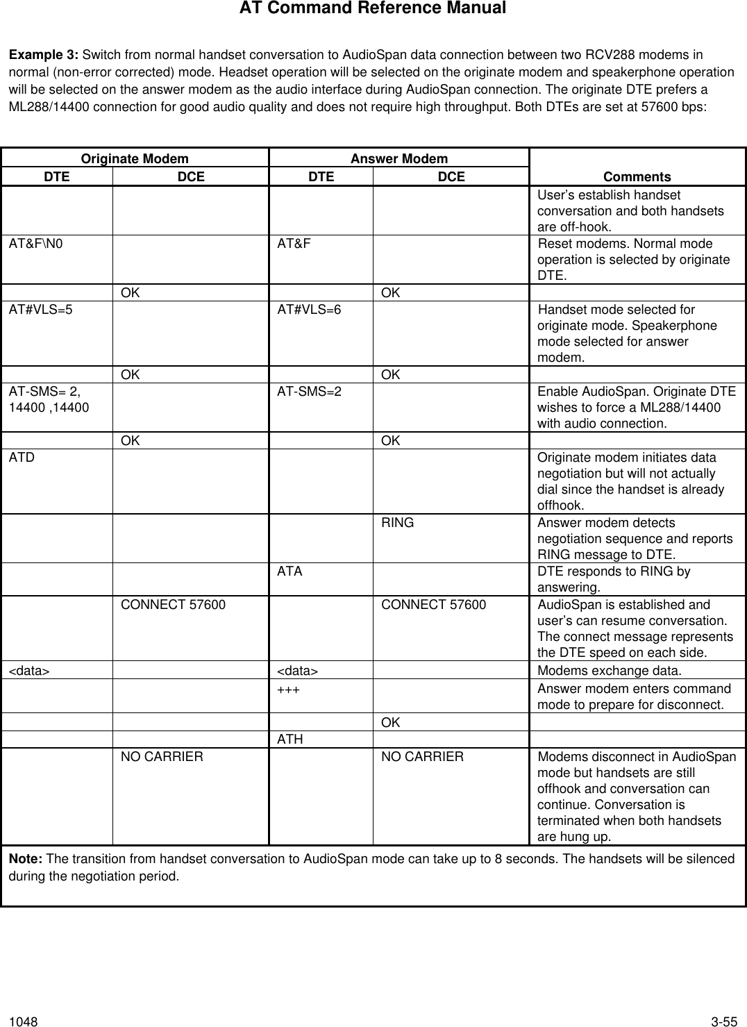
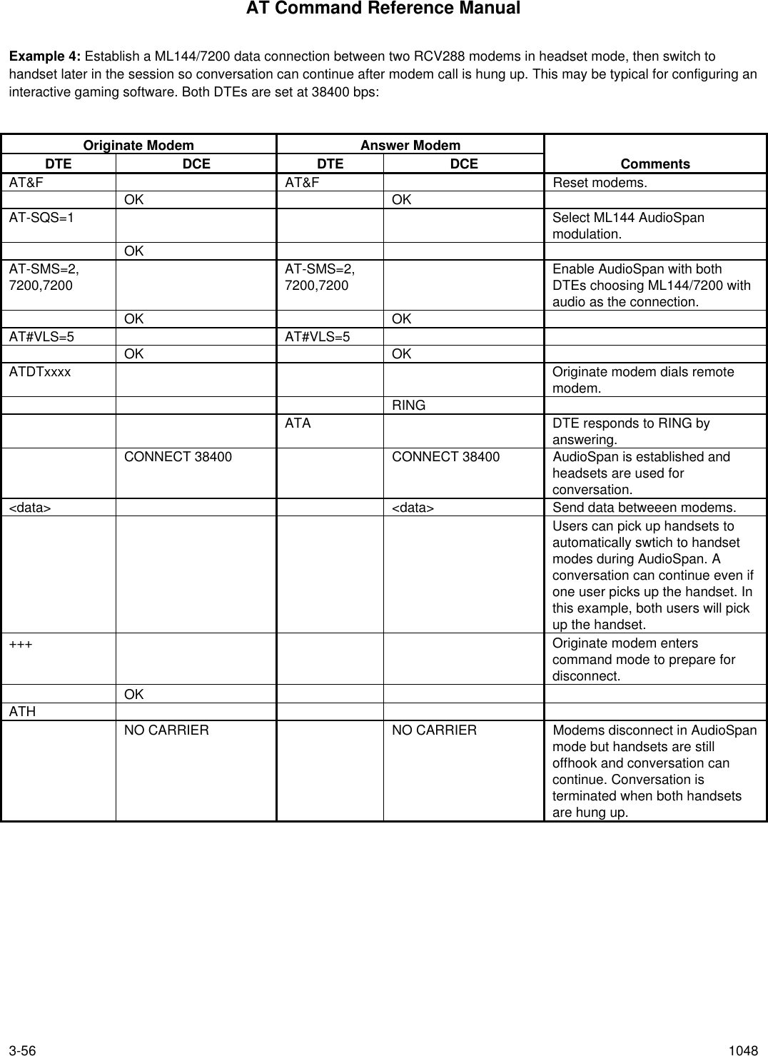
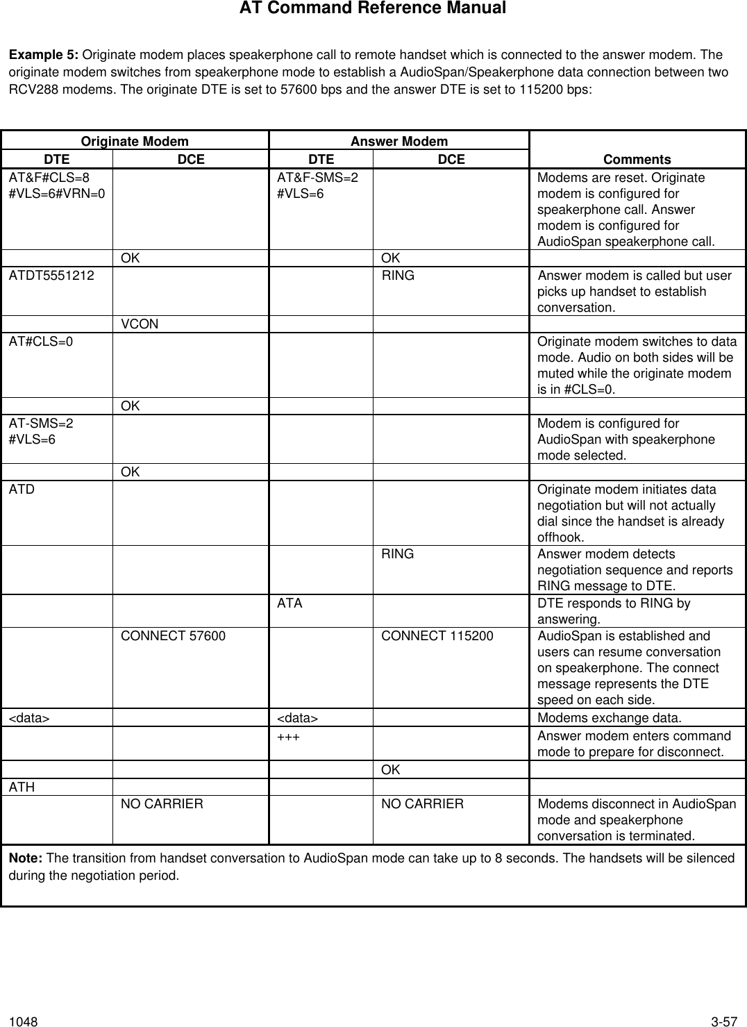
![AT Command Reference Manual3-58 10483.10 SYNCHRONOUS ACCESS MODE3.10.1 Synchronous Access Mode CommandsThree commands support Synchronous Access Mode:+ES Enables and disables Synchronous Access Mode in the client or central site modem+ESA Configures the operation of the Synchronous Access Submode+ ITF Selects Transmit Flow Control ThresholdsEnabling Synchronous Access Mode enables the use of the 8-bit command characters defined in Table 9/V.80 of the DraftITU-T Recommendation V.80 (DATA COMMUNICATION OVER THE TELEPHONE NETWORK; In-Band DCE Control andSynchronous Data Modes for Asynchronous DTE).+ES - Enable Synchronous Access ModeThis extended-format command specifies the initial requested mode of operation when the modem is operating as theoriginator, optionally specifies the acceptable fallback mode of operation when the modem is operating as the originator, andoptionally specifies the acceptable fallback mode of operation when the modem is operating as the answerer. The commandformat is:+ES=[<orig_rqst>[,<orig_fbk>[,<ans_fbk>]]]This extended-format compound parameter is used to control the manner of operation of the V.42 protocol in the modem (ifpresent). It accepts three numeric subparameters:<orig_rqst> Specifies the initial requested mode of operation when the modem is operating as the originator.The options are:3 Initiate V.42 with Detection Phase. (Default.)6 Initiate Synchronous Access Mode when connection is completed, and Data State isentered.7 Initiate Frame Tunneling Mode when connection is completed, and Data State is entered.<orig_fbk> Specifies the acceptable fallback mode of operation when the modem is operating as theoriginator. This subparameter should not be commanded.<ans_fbk> Specifies the acceptable fallback mode of operation when the modem is operating as theanswerer. The options are:2 Error control optional (either LAPM or Alternative acceptable); if error control notestablished, maintain DTE-modem data rate and use local buffering and flow controlduring non-error-control operation. (Default.)8 Initiate Synchronous Access Mode when connection is completed, and Data State isentered.9 Initiate Frame Tunneling Mode when connection is completed, and Data State is entered.Examples:+ES=6 Enable Synchronous Access Mode originator (client modem only)+ES=,,8 Enable Synchronous Access Mode answerer (client modem only)+ES=6,,8 Enable Synchronous Access Mode originator and answerer (client modem only)+ES=7 Enable Frame Tunneling Mode originator (central site modem only)+ES=,,9 Enable Frame Tunneling Mode answerer (central site modem only)+ES=7,,9 Enable Frame Tunneling Mode originator and answerer (central site modem only)+ES=3 Disable Synchronous Access Mode originator+ES=,,2 Disable Synchronous Access Mode answerer+ES=3,,2 Disable Synchronous Access Mode originator and answerer](https://usermanual.wiki/Itron/921.Modem-User-Manual/User-Guide-100350-Page-76.png)
![AT Command Reference Manual1048 3-59Reporting Selected OptionsThe modem reports the selected options in response to the following command:+ES?The response is:+ES: <orig_rqst>,<orig_fbk>,<ans_fbk>Example:+ES?+ES: 3,0,2 For the defaults.+ES: 6,0,8 Synchronous Access Mode originator and answerer enabled (client modem only)+ES: 7,0,9 Frame Tunneling Mode originator and answerer enabled (central site modem only)Reporting Supported OptionsThe modem reports the supported options in response to the following command:+ES=?The response is:+ES: (list of supported <orig_rqst> values),(list of supported <orig_fbk> values),(list of supported <ans_fbk> values)For example:+ES=?+ES: (0-7),(0-4),(0-9)+ESA - Configure Synchronous Access SubmodeThe operation of the Synchronous Access sub-Mode is configured by the +ESA parameter. The command format is:+ESA=[<trans_idle>[,<framed_idle>[,<framed_un_ov>[,<hd_auto>[,<crc_type>[,<nrzi_en>[,<syn1>[,<syn2>]]]]]]]]This extended-format compound parameter is used to control the manner of operation of the Synchronous Access Mode inthe modem. It accepts six numeric subparameters:<trans_idle> Specifies the bit sequence transmitted by the modem when a transmit data buffer underruncondition occurs, while operating in Transparent sub-Mode. The options are:0 In Transparent sub-Mode, modem transmits 8-bit SYN sequence on idle. Modemreceiver does not hunt for synchronization sequence (default and fixed).<framed_idle> Specifies the bit sequence transmitted by the modem when a transmit data buffer underruncondition occurs immediately after a flag, while operating in Framed sub-Mode. The options are:0 In Framed sub-Mode, modem transmits HDLC flags on idle (default and fixed).<framed_un_ov> Specifies the actions undertaken by the modem when a transmit data buffer underrun or overruncondition occurs immediately after a non-flag octet, while operating in Framed sub-Mode.0 In Framed sub-Mode, modem transmits abort on underrun in middle of frame (default).1 In Framed sub-Mode, DCE transmits a flag on underrun in middle of frame, and notifiesDTE of underrun or overrun.<hd_auto> Specifies whether or not, in V.34 half-duplex operation, additional procedures besides thosespecified in § 12/V.34 shall be performed by the modem when switching from primary channel tosecondary channel operation, and vice versa. This subparameter should not be commanded.](https://usermanual.wiki/Itron/921.Modem-User-Manual/User-Guide-100350-Page-77.png)
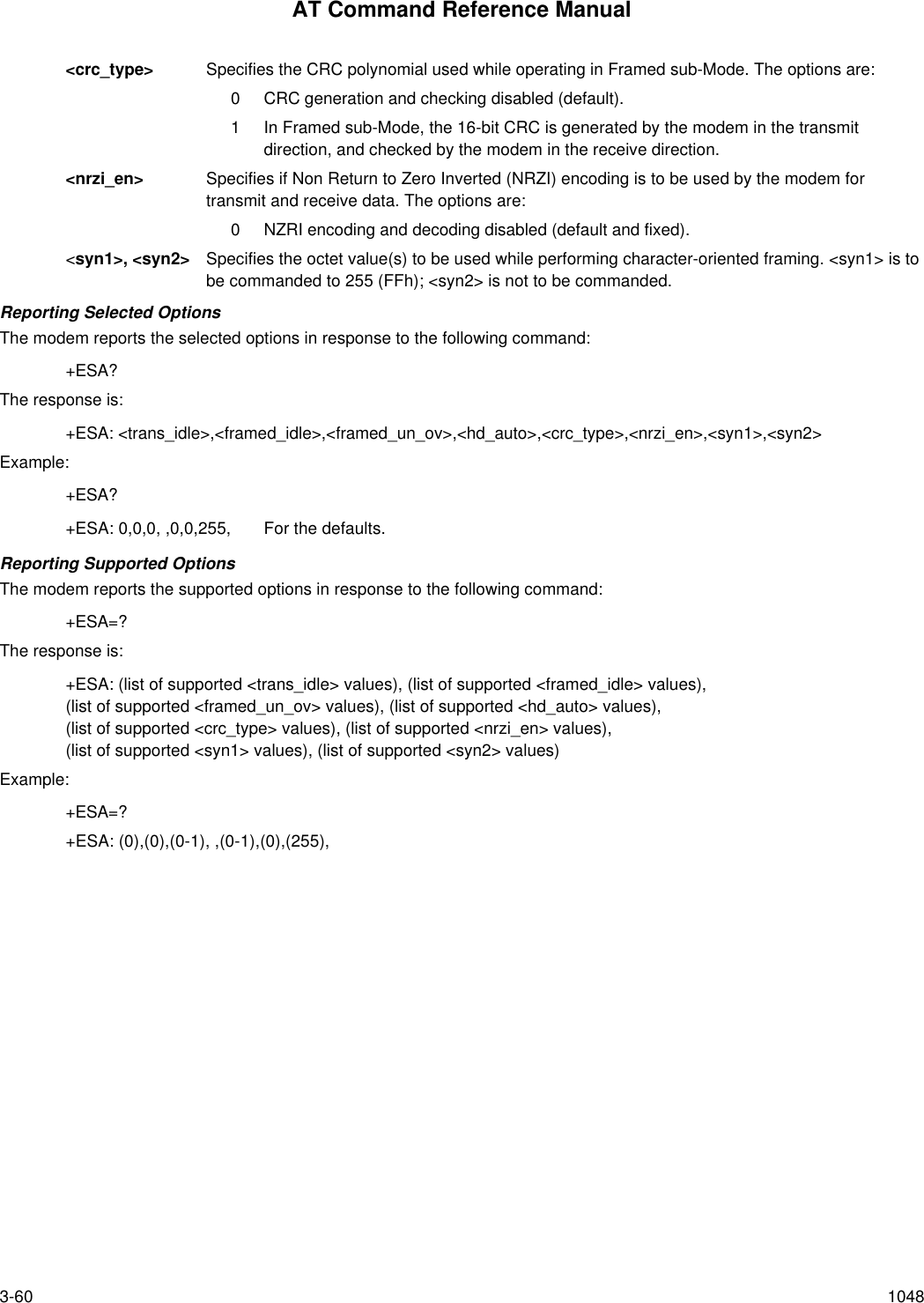
![AT Command Reference Manual1048 3-61+ ITF - Transmit Flow Control ThresholdsThe +ITF command determines the flow control thresholds used by the modem for transmit data from the DTE. Thecommand format is:+ITF=[<off>[,<on>[,<report_period>]]]This optional compound parameter allows the DTE to determine the input buffer size in the modem for data on circuit 103(transmit data) from the DTE, to control the threshholds used for flow control of such data, and to control how often themodem reports to the DTE the number of octets in this buffer. Note that the DTE can adjust its own threshholds for flowcontrol of data on circuit 104 (received data) from the modem.<off> Determines the threshhold, in octets, above which the modem will generate a flow off signal.Applicable in Synchronous Access and Frame Tunneling modes. Default <off> value is 255.For the <on> and <off> subparameters, the input buffer is assumed to reside between themodem’s V.24 interface and the Synchronous Access protocol layer; i.e., the buffer countincludes all octets, including EM codes, received from the DTE, with the exception of DC1 andDC3 if these are used to signal <modem-by-DTE> flow control.The modem returns the ERROR result code if the DTE specifies that the <off> subparameter beset to a value less than or equal to the <on> subparameter; in this case, the current parametervalue settings are not modified.<on> Determines the threshhold, in octets, below which the modem will generate a flow on signal.Applicable in Synchronous Access and Frame Tunneling modes. Default <on> value is 64.<report_period> Not supported. A fixed value of zero is used and reported.Reporting Selected OptionsThe modem sends a string of information text to the DTE consisting of selected options in response to the followingcommand:+ITF?The response is:+ITF: <off>,<on>,<report_period>Example:+ITF?+ITF: 255,64,0 Default valuesReporting Supported OptionsThe modem sends a string of information text to the DTE consisting of supported options in response to the followingcommand:+ITF=?The response is:+ITF: (list of supported <off> values),(list of supported <on> values),(list of supported <report_period> values)Example:+ITF=?+ITF: (0-255),( 0-255),(0)The maximum reported <off> value is the input transmit data buffer level at which the modem signals a transmit dataoverrun indication to the DTE.](https://usermanual.wiki/Itron/921.Modem-User-Manual/User-Guide-100350-Page-79.png)


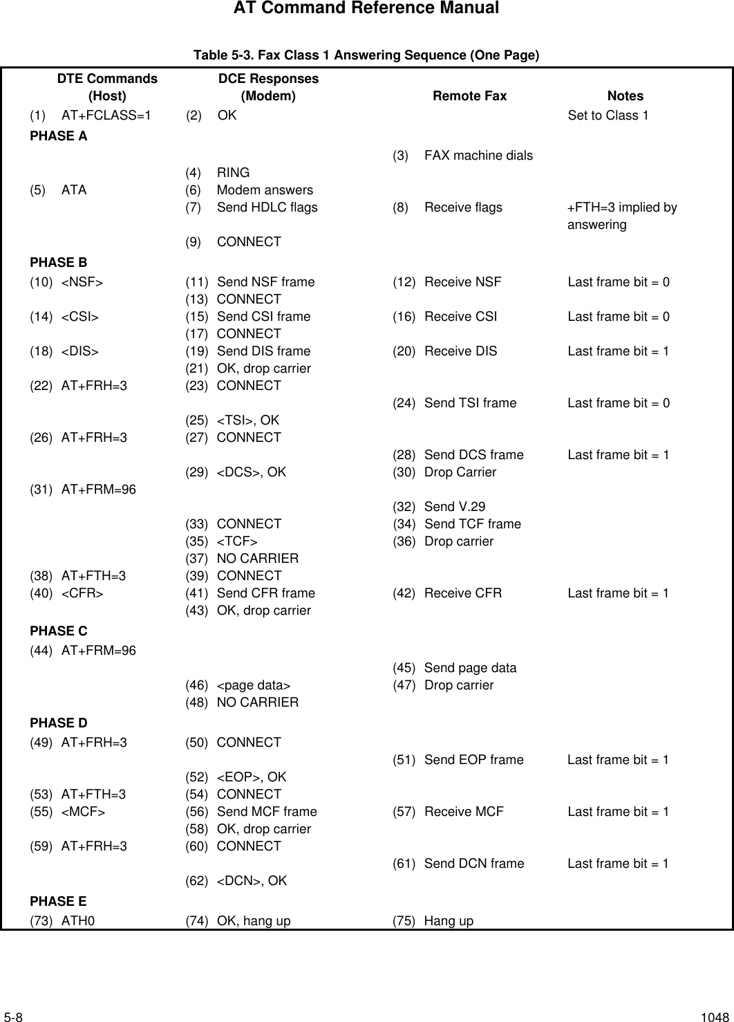
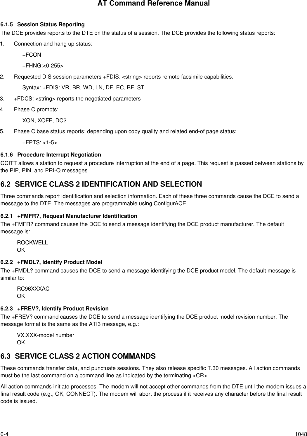
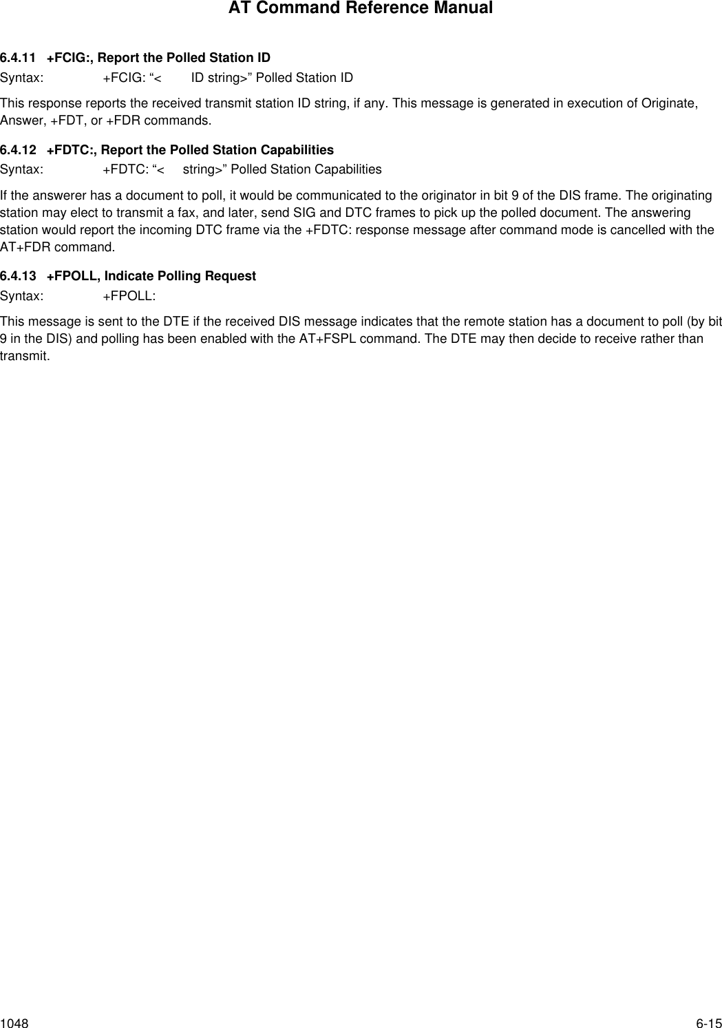
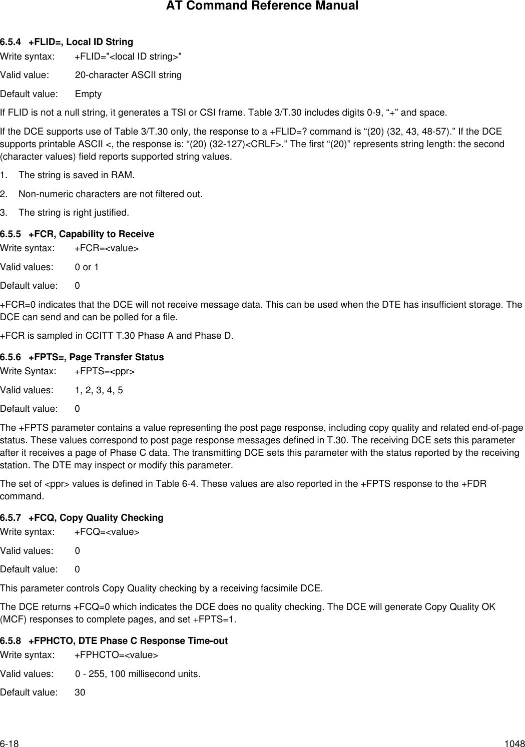
![AT Command Reference Manual1048 6-56.3.1 ATD, Originate a CallSyntax: ATD....<CR>The DCE can support a DTE command to originate a call using the ATD command (see Section 3.2).If this command is unsuccessful, the DCE reports an appropriate failure or error type result code such as NO CARRIER, NODIALTONE, or BUSY (see Section 3.3).If this call is successful, the typical DCE response is:ATDnn..nn (go off-hook, dial, get CED)+FCON (DCE detects flags)[+FCSI:<remote ID string>]+FDCS:<T.30 subparameter string>OKThe DCE dials, detects call progress, and generates the CNG tone. It then waits for a DIS frame. On detection of the firstPhase B preamble (V.21 ch. 2 modulated by 300 bps HDLC flags), it reports the “+FCON” message to the DTE. The DCEthen switches to 19200 bps.The DCE generates a DCS frame based on the received DIS frame and on the previously set +FDIS parameter. A +FDTcommand from the DTE releases the DCE to transmit that DCS frame.The DCE reports the initial received T.30 negotiation messages, including the DIS frame and the optional CSI ID string. The+FDIS: report is followed by the OK final result code.6.3.2 ATA, Answer a CallThe DCE can support a DTE command to answer an incoming call using the ATA command (see Section 3.2).The DTE may issue an Answer command in response to an incoming ring.If the Answer command is unsuccessful, the DCE will report an appropriate failure or error type result code, such as NOCARRIER (see Section 3.3).Manual Call AnswerIf this call is successful, the typical DCE response (answer and receive) is:+FCON[+FTSI:<remote ID string>]+FDCS:<T.30 subparameter string>OK(DTE should issue +FDR command here)Upon receipt of an Answer command from the DTE, the DCE answers and generates the CED tone. The DCE thengenerates a DIS frame (derived from the +FDIS parameter) and hunts for the first T.30 negotiation frames. Upon detectionof the first Phase B preamble (V.21 ch 2 modulated by 300 bps HDLC flags), it reports the “+FCON” message to the DTE.The DTE should report the initial received T.30 negotiation messages, including the DCS frame. The +FDCS: report will befollowed by the OK final result code.Automatic AnswerThe modem provides for automatic answering of incoming calls. If configured for automatic answer, the modem answers anincoming call in compliance with T.30, and reports the same messages as described for manual answer.Connection as a Data ModemIf configured to do so by the +FAA parameter, the DCE will adaptively answer as a facsimile DCE or as a data DCE. If theDCE answers as a data DCE, it resets the +FCLASS parameter to 0 and issues the appropriate final result code (e.g.,CONNECT, or NO CARRIER) to the DTE.](https://usermanual.wiki/Itron/921.Modem-User-Manual/User-Guide-100350-Page-115.png)
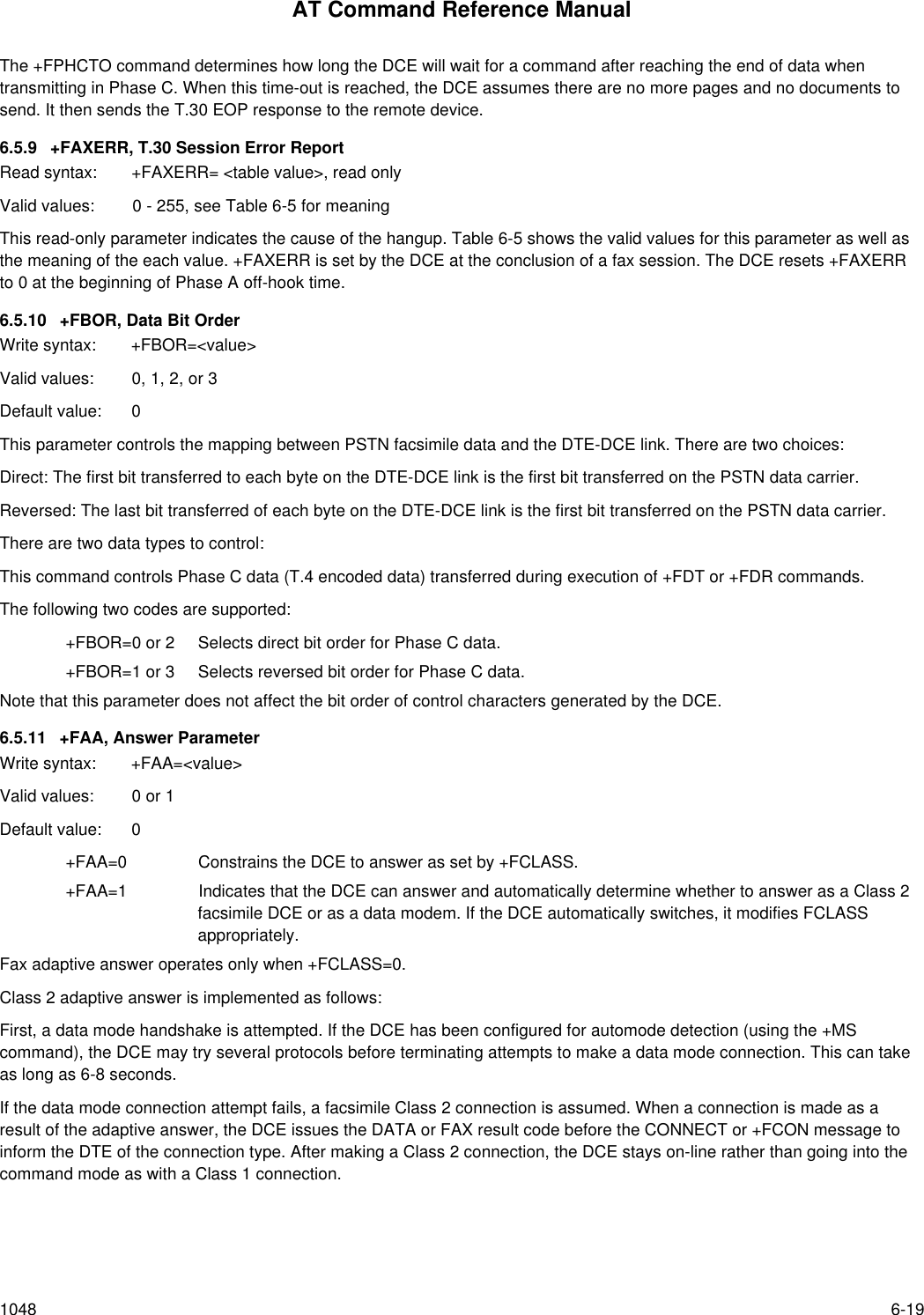
![AT Command Reference Manual6-6 10486.3.3 +FDT, Data TransmissionSyntax: +FDT <CR>The +FDT command prefixes Phase C data transmission. When the DCE is ready to accept Phase C data, it issues thenegotiation responses and the CONNECT result code to the DTE.In Phase B, the +FDT command releases the DCE to proceed with negotiation, and releases the DCS message to theremote station. In Phase C, the +FDT command resumes transmission after the end of a prior transmit data stream.Initiate Page TransmissionPhase B DCE polled response:[+FCSI:<remote ID string>] - if new CSI received[+FDIS:<subparameters from remote station>] - if new DIS received+FDCS:<T.30 subparameter string>CONNECT<XON> - when ready for dataAfter placing a call, or after finishing a document exchange, the DTE may command the DCE to re-enter T.30 Phase B toattempt to negotiate a document transmission.Continue a PageCONNECT<XON>The DTE may issue more than one +FDT command for a given page, so that different files may be concatenated together.These files must have the same format.Phase C Data FramingPhase C data must be presented to the DCE in stream mode. The DCE expects Phase C data to follow until it detects<DLE><ETX> termination characters. The DCE will filter the stream as described in Section 6.1.2.The DCE will acknowledge the end of the data by returning the OK result code to the DTE.If there is data underrun before the next +FDT or +FET= command, the DCE will zero-fill the pad as per T.4 until the PhaseC timeout (+FPHCTO) is reached, or until more data is received. The DCE appends an RTC pattern to the transmit dataafter an +FET= command is received from the DTE.Phase C Data FormatThe Phase C data will be of the format specified by the negotiated T.30 DCS frame. The +FDCS:<string> response isdefined in Section 6.4.2. The subparameter values are described in Table 6-2.The DCE will use the negotiated minimum Scan Time parameter from the DCS frame, and insert sufficient fill bits to padeach line to the minimum scan time. This is reported in the +FDCS:ST subparameter.If the DCE finds more than one consecutive EOL in Phase C data (e.g., RTC), it will send only one EOL.1. Phase C data must conform to T.4 specifications.2. The DTE need not include a final RTC, since the DCE will append an RTC in response to an FET= command.3. Some facsimile machines may treat two EOLs as an RTC.<CAN>, Escape from TransmissionThe DCE may request the DTE to halt Phase C transmission, by sending a cancel <CAN> character (024) to the DTE. In thiscase, the DTE should terminate Phase C transmission, issue <CAN>, and wait for the OK response code from the DCE.](https://usermanual.wiki/Itron/921.Modem-User-Manual/User-Guide-100350-Page-116.png)
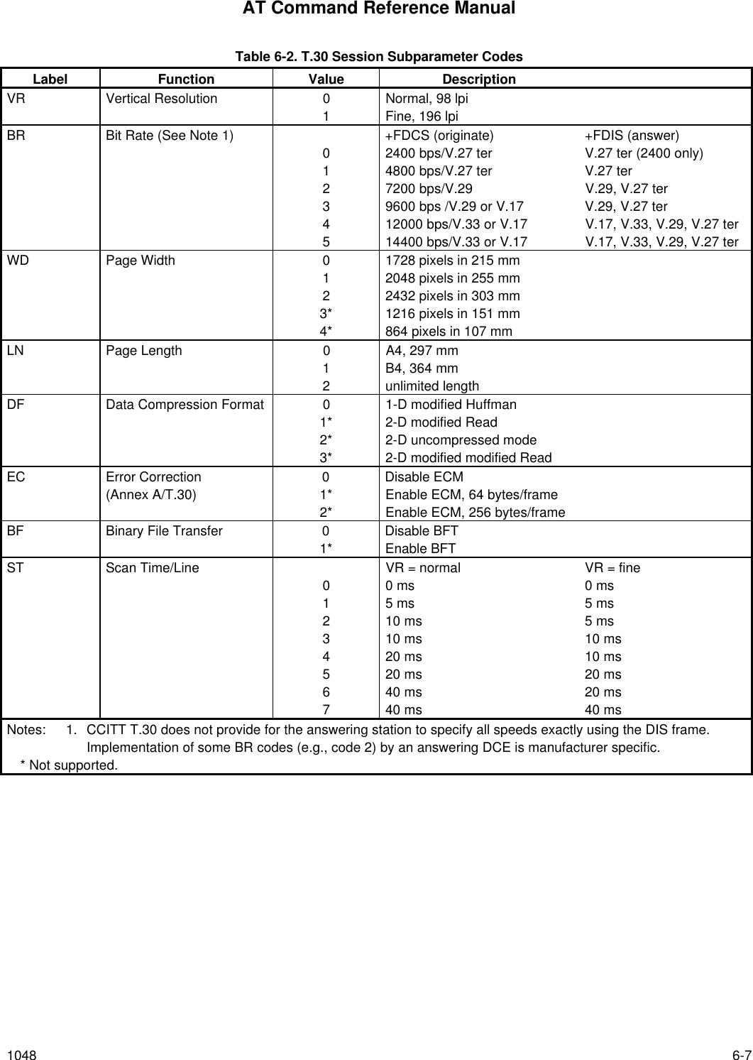
![AT Command Reference Manual6-8 10486.3.4 +FET, Transmit Page PunctuationSyntax: +FET=<ppm>[,<pc>,<bc>,<fc>]DCE response:+FPTS:<ppr> - when receive from remote OKThis command is used to punctuate page and document transmission after one or more +FDT commands. This commandgenerates T.30 Post Page Messages selected by the <ppm> code (Table 6-3).The +FET=<ppm> command indicates that the current page is complete; no more data will be appended to it. The valueindicates whether there are any additional pages are to be sent and, if so, whether there is a change in any of the documentparameters.The DTE can command the DCE to generate PRI-Q messages with the +FET=<ppm> command using ppm codes 4-6(Table 6-3).This command must be sent within the time out specified by +FPHCTO after sending Phase C data, or else the DCE will endthe page and document transmission. If the Phase C timeout is reached, the DCE sends an EOP post page message andterminates the session.The remote facsimile station should respond to the post page message with a post page response. The DCE will report thisusing the +FPTS:<ppr> response (Table 6-4).End a PageThe +FET= command causes the DCE to append an RTC (6 EOL) pattern as needed and enter Phase D by sending theselected T.30 Post Page message.The +FET=1 (EOM) command signals the remote station that the next document will have a new DCS negotiated; thiscauses the session to re-enter Phase B. Table 6-3. T.30 Post Page Message Codesppm Code Mnemonic Description0 [PPS-]MPS Another page next, same document1 [PPS-]EOM Another document next2 [PPS-]EOP No more pages or documents3 PPS-NULL Another partial page next4 [PPS-]PRI-MPS Another page, procedure interrupt5 [PPS-]PRI-EOM Another doc., procedure interrupt6 [PPS-]PRI-EOP All done, procedure interrupt=8+ppm Post Page Message (ppm code) Table 6-4. T.30 Post Page Response Messagesppr Code Mnemonic Description1 MCF Page good2 RTN Page bad; retrain requested3 RTP Page good; retrain requested4 PIN Page bad; interrupt requested5 PIP Page good; interrupt requested](https://usermanual.wiki/Itron/921.Modem-User-Manual/User-Guide-100350-Page-118.png)
![AT Command Reference Manual1048 6-96.3.5 +FDR, Begin or Continue Phase C Receive DataSyntax: +FDR <CR>Default value: 3 seconds in some placesThe +FDR command initiates transition to Phase C data reception. This can occur after answering, dialing, a document isreceived, or a page is received.The DCE reports the negotiated T.30 parameters, with the remote ID information if available. When the DCE is ready tocommence data transfer, it issues a CONNECT response code. If the DCE cannot resume data transfer because there is nomore data, it responds OK. When the DTE is ready to accept data, it issues an <DC2> character (018) to the DCE.If the DTE issues an <XOFF> character to the DCE for flow control, the DCE signals the DTE when its buffers are empty bysending a <DLE><DC2> (<016><018>) character pair.When the DCE delivers the last byte of a page, the DCE reports the Page Transfer Status via the +FPTS:<ppr> response(Table 6-4).After a Page Transfer Status Report, the DCE reports the post page message from the remote facsimile station via the+FET:<ppm> response (Table 6-3) which signals the intentions of the remote station.The DCE holds the post page response message to the remote facsimile station (MCF, etc.), represented in the +FPTSparameter until the next +FDR command. The DTE may modify the +FPTS parameter before issuing the +FDR commandwhich releases that message. The DTE must issue a +FDR command to release Post Page Messages.Initiate Document ReceptionThe +FDR command may be issued in Phase B after an answer command, or in Phase B after a previous document.The DCE response in stream mode is:+FCFR when CFR sent[+FTSI:<remote ID string>] if new TSI received+FDCS:<T.30 subparameter string>] if new DCSCONNECT(<DC2> needed from DTE here)<Phase C data stream><DLE><ETX>+FPTS:<ppr>, <lc> [,<blc>, <cblc>]+FET:<ppm>OK(DTE must issue +FDR command to release post page response)](https://usermanual.wiki/Itron/921.Modem-User-Manual/User-Guide-100350-Page-119.png)
![AT Command Reference Manual6-10 1048Continue Document ReceptionThe DTE may issue a +FDR command in Phase D, which releases the post page message, and indicates readiness toreceive another page after receipt of a Multipage (+FET:0) or PPS-NULL (+FET:3) message. The DCE response will be:CONNECT(<DC2> needed from DTE here)<Phase C data stream)<DLE><ETX>+FPTS:<ppr>, <lc> [,<blc>, <cblc>]+FET:<ppm>OK(DTE must issue +FDR command to release post page response)If done receiving:+FHNG: <hangup cause code>OKContinue page receptionPhase C Data FramingPhase C data may be presented to the DTE in stream mode. The DCE will transfer a stream of data to the DTE, followed bythe <DLE><ETX> stream termination characters. The DCE will filter the stream as described in Section 6.1.2.Phase C Data FormatThe received data format is negotiated under T.30 reported by the +FDCS:VR,BR,WD,LN,DF,EC,BF,ST response.The DCE will delete the terminating RTC (6 EOLs) patterns.<CAN>, Escape from ReceptionFrom the +FDR command until the end of Phase D Date, the DCE is in a data transfer state, and will not respond to DTEcommand characters. The DCE will respond to three ASCII control characters: <DC1> (017) and <DC3> (019) flow controlcharacters, and cancel <CAN> (024).Upon receipt of the <CAN> character, the DCE will terminate the reporting of received data by sending trailing <DLE><ETX>characters to the DTE, and will then execute an implied +FK command in order to conduct an orderly disconnection.6.3.6 +FK, Session TerminationSyntax: +FKThe +FK command causes the DCE to terminate the session in an orderly manner. In particular, the DCE will send a DCNmessage at the next opportunity and hang up. At the end of the termination process, the DCE will report the +FHNGresponse with result code (Table 6-5).This operation can be invoked by using the cancel <CAN> character during Phase C data reception (see prior section)The DCE will wait until the current page completes, unless the reception is of unlimited length; in that case, the DCE mayhalt reception and terminate the session at any time.](https://usermanual.wiki/Itron/921.Modem-User-Manual/User-Guide-100350-Page-120.png)
![AT Command Reference Manual6-14 10486.4.7 +FPTS:, Receive Page Transfer StatusSyntax: +FPTS:<ppr>, <lc> [,<blc>, <cblc>]The +FPTS:<ppr> is generated by the DCE at the end of Phase C data reception in execution of a +FDR command.The <ppr> is generated by the DCE; it depends on the DCE capabilities at T.4 error checking. See Table 6-4 for <ppr>values.The receiving DCE will count the lines. These values are;<lc> = line count<blc = bad line count<cblc> = <consecutive bad line countA receiving DTE may inspect <ppr> and write a modified value into the +FPTS parameter. The DCE will hold thecorresponding Post Page Response message until released by a +FDR command from the DTE.6.4.8 +FET:, Post Page Message ResponseSyntax: +FET:<ppm>The +FET:<post page message> response is generated by a receiving DCE after the end of Phase C reception on receipt ofthe post-page message from the transmitting station. The +FET:<ppm> response is generated in execution of a +FDRcommand. The <ppm> codes respond to the T.30 post page messages (Table 6-3).6.4.9 +FPTS:, Transmit Page Transfer StatusSyntax: +FPTS:<ppr>The +FPTS: response reports a <ppr> number representing the copy quality and related post-page message responsesreceived from the remote DCE. The valid <ppr> values are defined in Table 6-4.The +FPTS:<ppr> response is generated in execution of a +FET=<ppm> command.6.4.10 +FHNG:, Call Termination with StatusSyntax: +FHNG:<hangup status code>+FHNG indicates that the call has been terminated. The hangup cause is reported and stored in the +FAXERR parameterfor later inspection. The <hangup status code> values are described in Table 6-5.+FHNG:<hsc> is a possible intermediate result code to any DTE action command described in Section 6.3. It is alwaysfollowed by the OK final result code.Upon termination of a call, the DCE determines the cause of termination and reports it as part of the FHNG:<hsc> response.It also stores this <hsc> code in the +FAXERR parameter for later inspection.The hangup values are organized according to the phases of the facsimile transaction as defined by T.30. In the FigureA/T.30 flow charts, there are decision boxes labelled “Command Received?"; this is referred to as COMREC in the table.Similarly, decision boxes labelled `Response Received?' are referred to as RSPREC in the table. A COMREC error orRSPREC error indicates that one of two events occurred: 1) a DCN (disconnect) signal was received, or 2) an FCS errorwas detected and the incoming signal was still present after 3 seconds. (See Figure A/T.30).The table values are in decimal notation. Leading zero characters are optional.](https://usermanual.wiki/Itron/921.Modem-User-Manual/User-Guide-100350-Page-124.png)
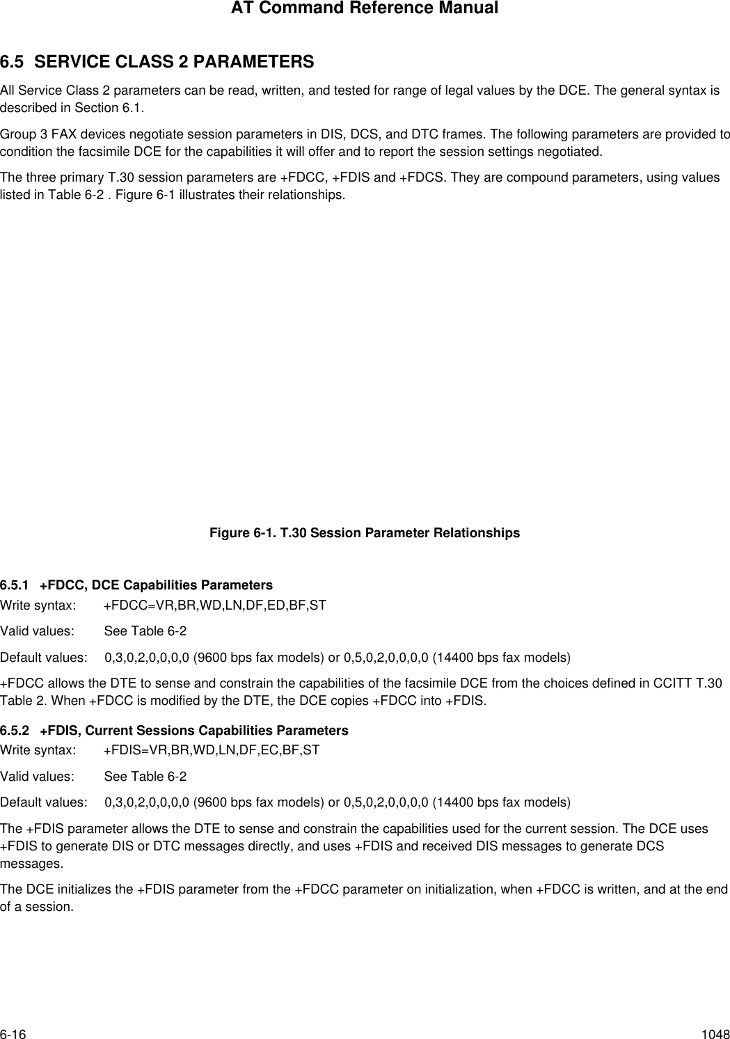
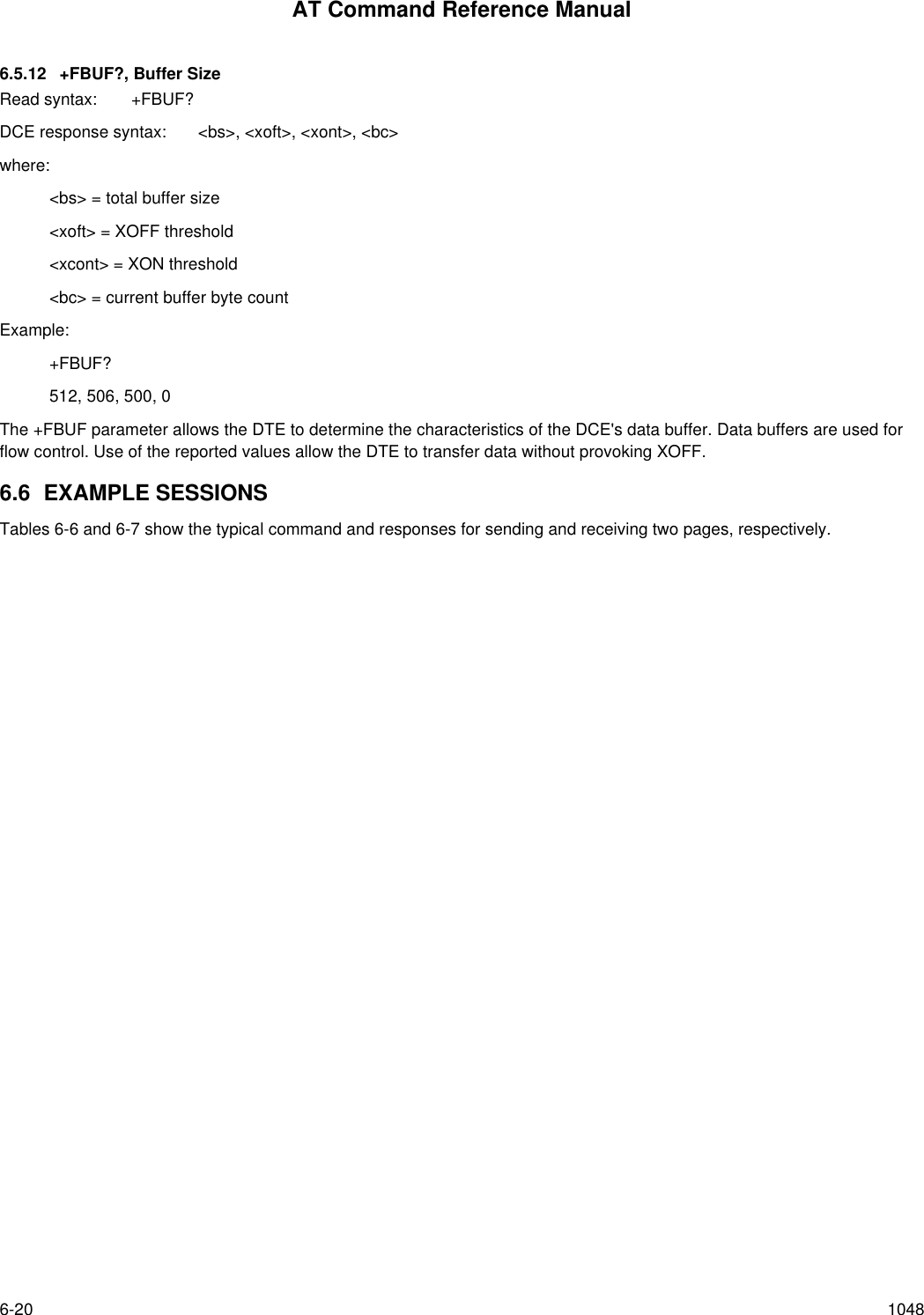
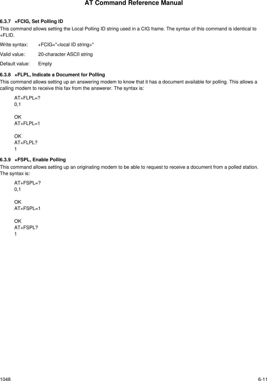
![AT Command Reference Manual1048 6-21 Table 6-6. Send Two Pages, 1-D, No ErrorsDTE Command DCE Response Local DTE Action Remote Station ActionAT+CLASS=2 OK Set Class 2 xAT+FLID="<local ID>" OK Set local IDAT<dial string>+FCON[+FCSI:"<csi>"]+FDIS: <dis codes>OKOff hook, dialSend CNGDetect flags[Get CSI]Get DISAnswer,Send [CED]V.21 flags[CSI]DISAT+FDT<1st page data><DLE><ETX>+FDCS:<DCS codes>CONNECT<XON>OK[Send TSI]Send DCSSend TCFGet CFRSend carrierSend page data[Get TSI]Get DCSGet TCFSend CFRReceive carrierReceive page dataAT+FET=0+FPTS:1OKSend RTCGet MPSGet MCFGet RTCGet MPSSend MCFAT+FDT<2nd page data><DLE><ETX>CONNECT<XON>OKSend carrierSend page dataReceive carrierReceive page dataAT+FET=2+FPTS:1+FHNG:0OKSend RTCSend EOPGet MCFSend DCNHang upGet RTCGet EOPSend MCFGet DCNHang up](https://usermanual.wiki/Itron/921.Modem-User-Manual/User-Guide-100350-Page-131.png)
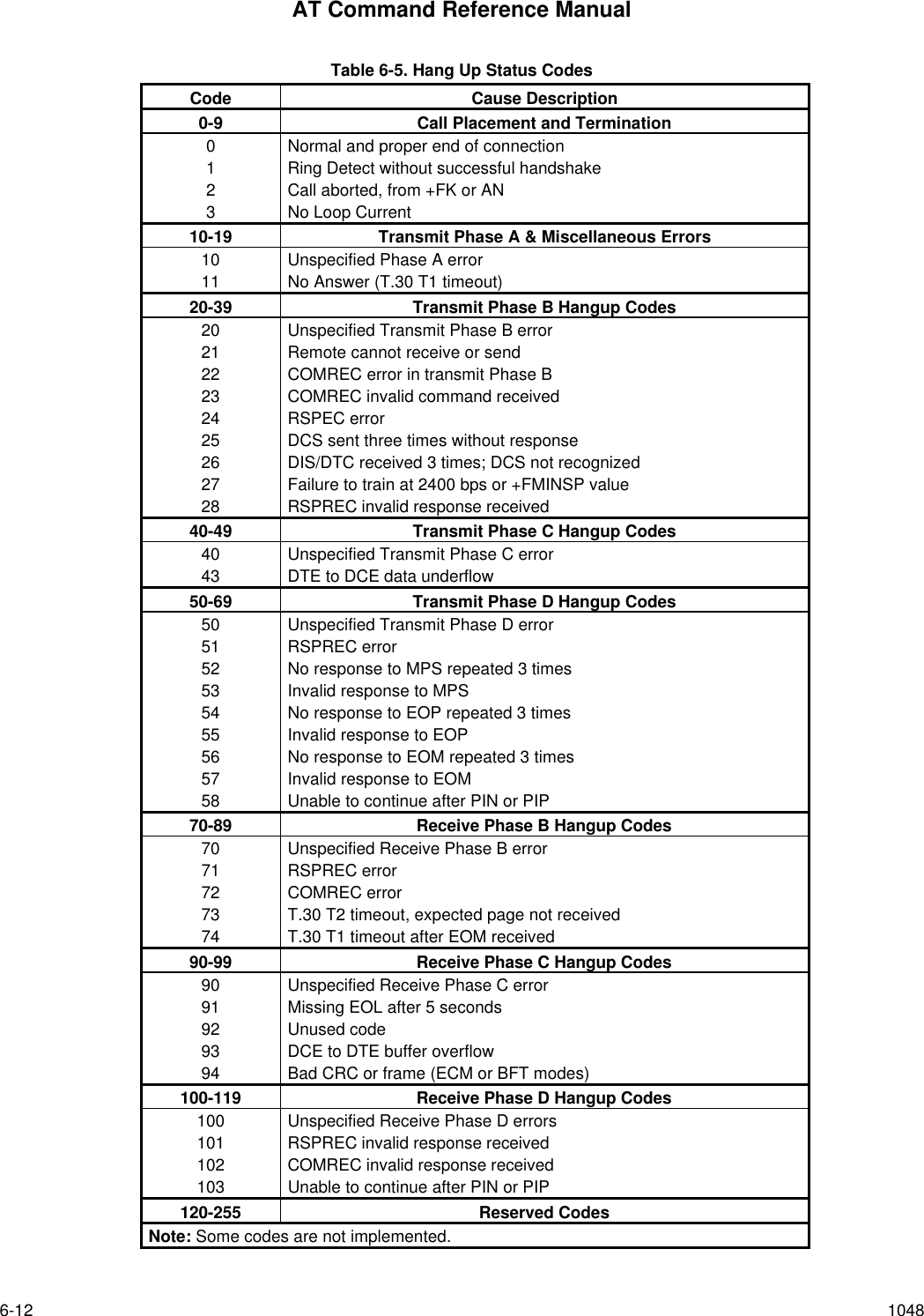
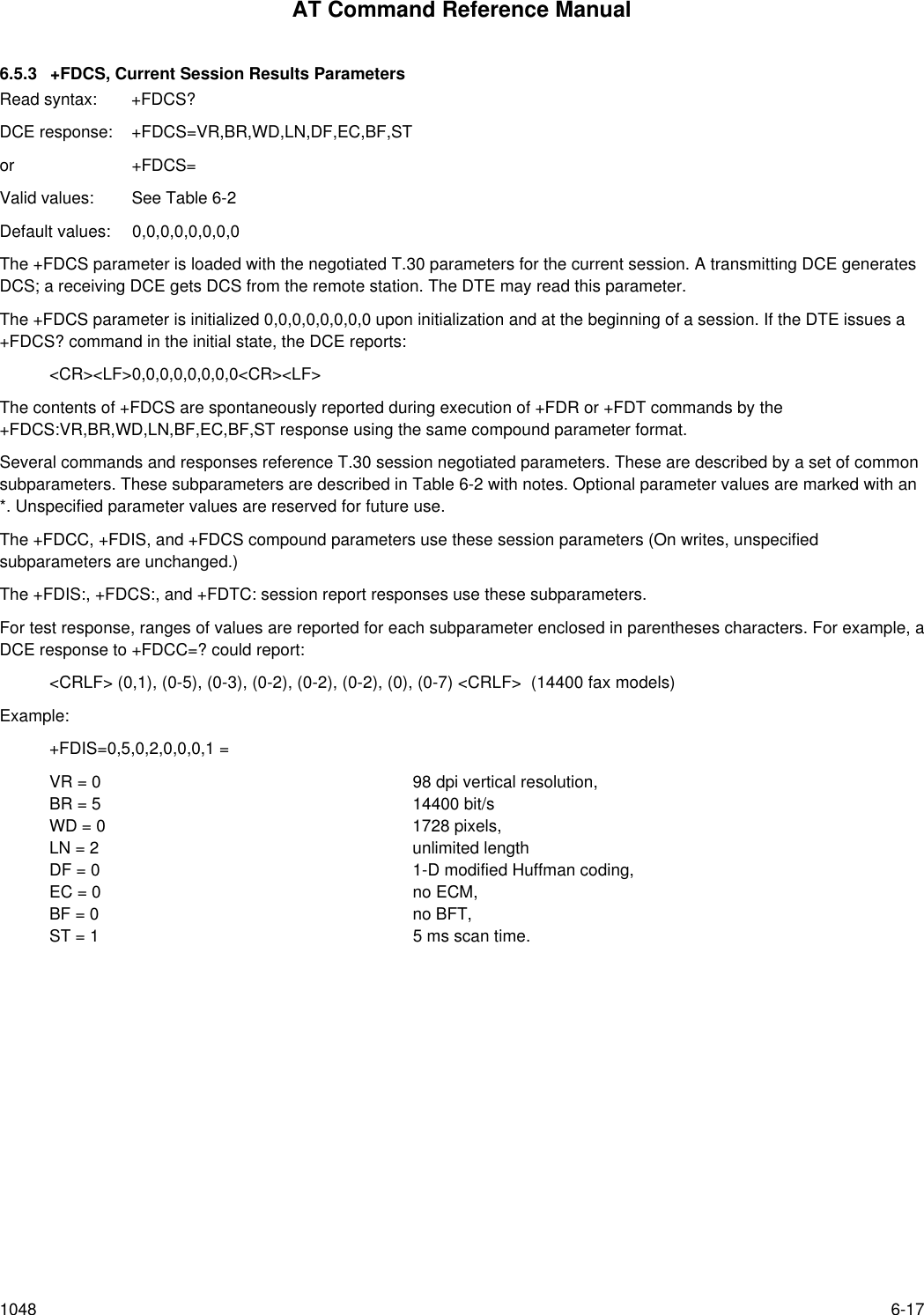
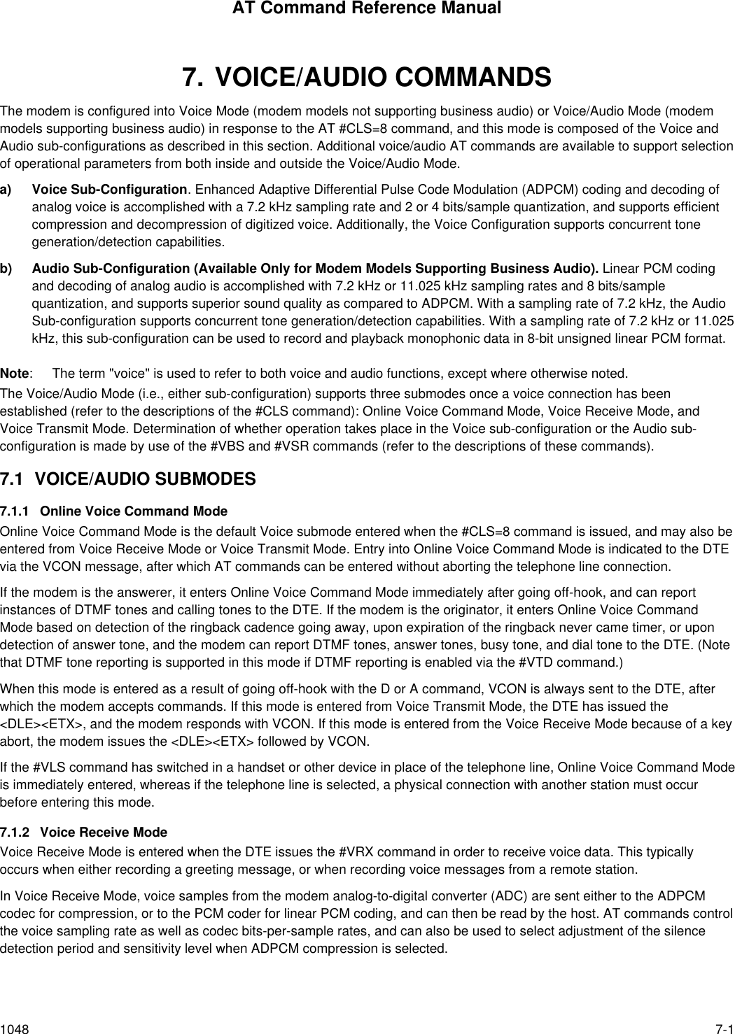
![AT Command Reference Manual6-22 1048 Table 6-7. Receive Two Pages, 1-D Data, No ErrorsDTE Command DCE Response Local DTE Action Remote Station ActionAT+FCR=1 OK Enable receptionAT+FLID="<local ID>" OK Set local ID RING Detect ring Dials[, Send CNG]ATA+FCON[+FTSI:"<tsi>"]+FDCS:<dcs codes>OKOff hookSend CEDSend CSISend DISDetect flags[Get TSI]Get DCSBegin TCF receiveGet CEDGet CSIGet DISSend V.21 flags[Send TSI]Send DCSStart TCFAT+FDR<DC2>+FCFR[+FDCS:"<dcs codes>]CONNECT<page data stream><DLE><ETX>+FPTS:1, <lc>+FET:0OKAccept TCFSend CFRGet page carrierGet page dataDetect RTCGet MPSFinish TCFGet CFRSend pager carrierSend page dataSend RTCDrop carrierSend MPSAT+FDR<DC2>CONNECT<page data stream><DLE><ETX>+FPTS:1, <lc>+FET:2OKSend MCFGet page carrierGet page dataDetect RTCGet EOPGet MCFSend page carrierSend page dataSend RTCDrop carrierSend EOPAT+FDR+FHNG:0OKSend MCFGet DCNGet MCFSend DCN](https://usermanual.wiki/Itron/921.Modem-User-Manual/User-Guide-100350-Page-132.png)
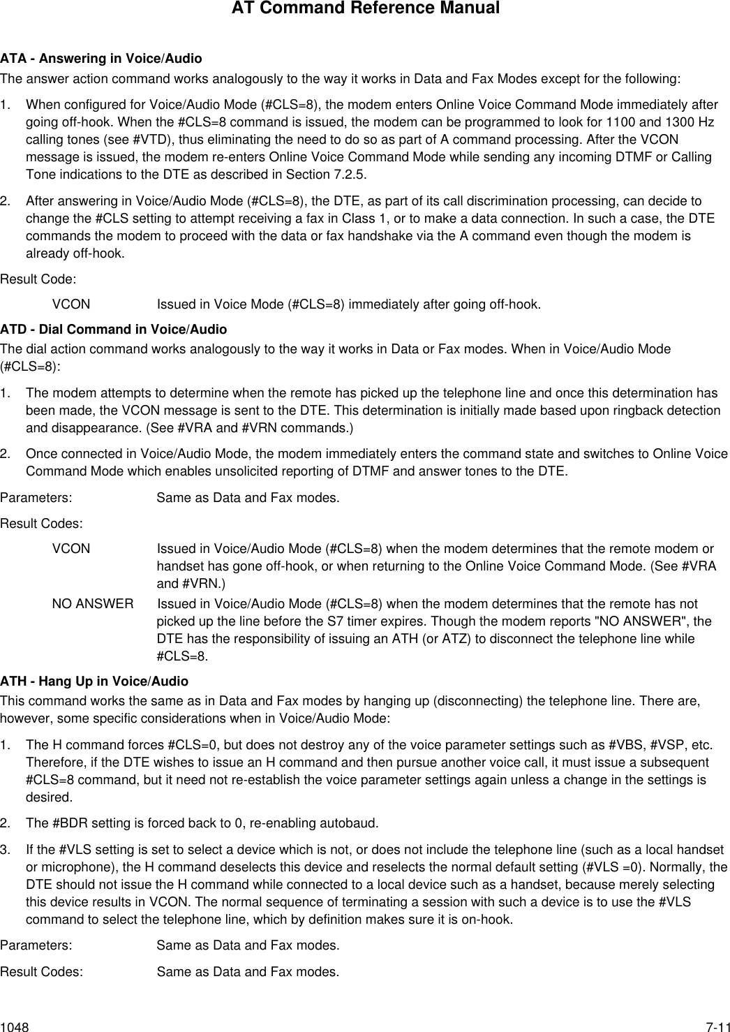
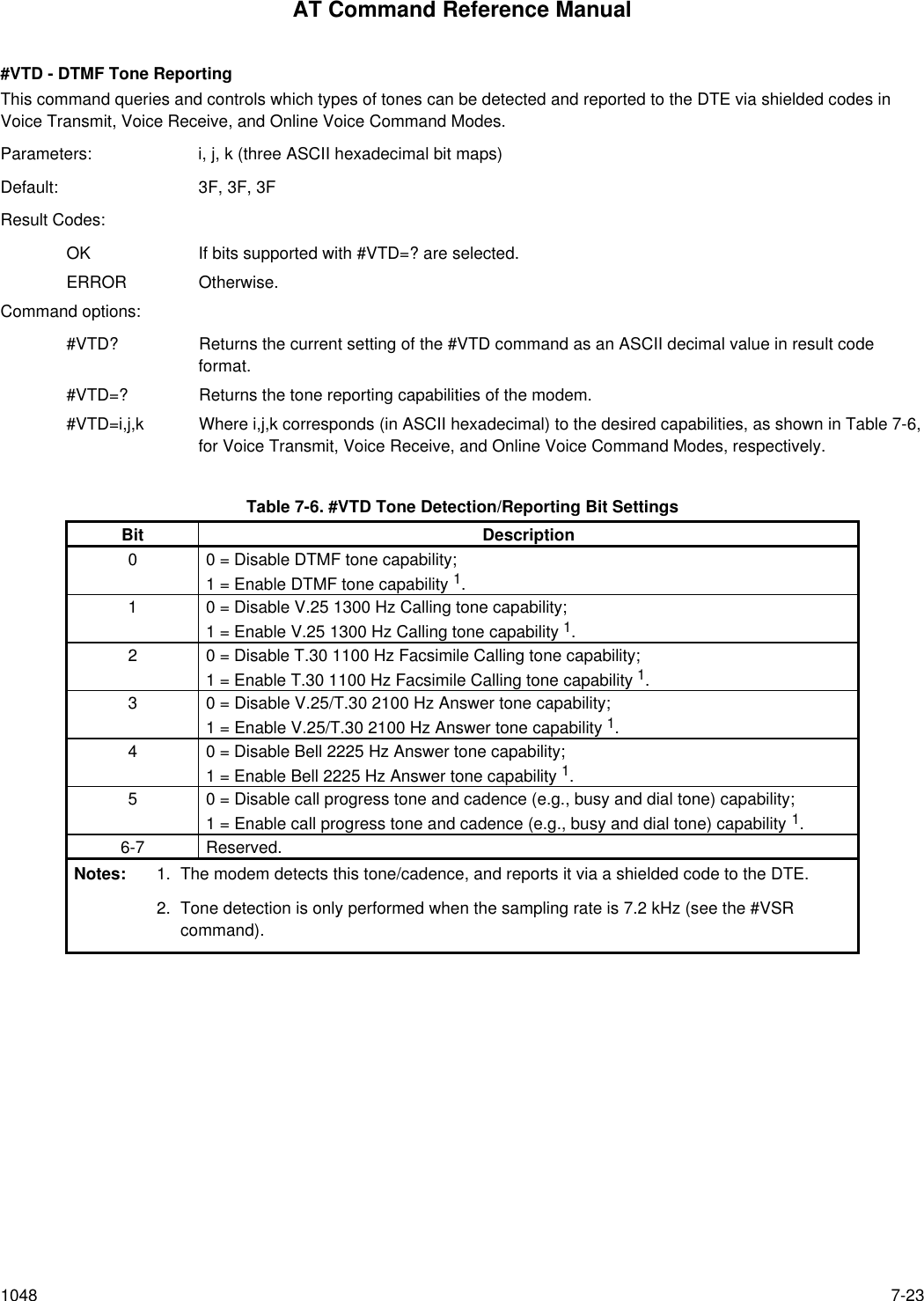
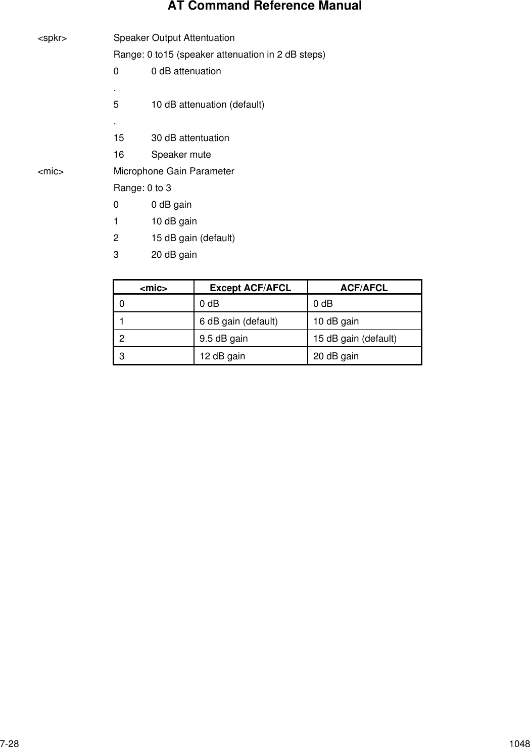
![AT Command Reference Manual7-12 1048ATZ - Reset from Voice ModeThis command works the same as in Data and Fax modes. In addition, the Z command resets all voice related parametersto default states, forces the #BDR=0 condition (autobaud enabled), and forces the telephone line to be selected with thehandset on-hook. No voice parameters are stored in NVRAM so the profile loaded does not affect the voice aspects of thiscommand. (Note that when #CLS=8, ATZ causes a hang up if the telephone line is connected.)Parameters: Same as Data and Fax modes.Result Codes: Same as Data and Fax modes.#BDR - Select Baud Rate (Turn off Autobaud)This command forces the modem to select a specific DTE/modem baud rate without further speed sensing on the interface.When a valid #BDR=n command is entered, the OK result code is sent at the current assumed speed. After the OK hasbeen sent, the modem switches to the speed indicated by the #BDR=n command it has just received.When in Online Voice Command Mode and the #BDR setting is nonzero (no autobaud selected), the modem supports a fullduplex DTE interface. This means that the DTE can enter commands at any time, even if the modem is in the process ofsending a shielded code indicating DTMF detection to the DTE. [Note that when #BDR has been set nonzero, the modememploys the S30 Disconnect Inactivity timer, and this timer starts at the point where #BDR is set nonzero. If this periodexpires (nominally 60 seconds) with no activity on the DTE interface, the modem reverts to #BDR=0, #CLS=0, and #VLS=0.]Parameters: n = 0 – 48 (New baud rate is n*2400 bps)Default: 0Result Codes:OK For the supported speeds.ERROR Otherwise.Command options:#BDR? Returns the current setting of the #BDR command as an ASCII decimal value in result codeformat.#BDR=? Returns a message indicating the speeds that are supported.#BDR=0 Enables autobaud detection on the DTE interface.#BDR=n Where 1<n<48. Sends OK message at current speed, then switches to the new speed defined byn*2400 bps unless and until another #BDR=n command is received. Autobaud is disabled, andthe character format is maintained at the format most recently detected.#CID - Enable Caller ID Detection and Select Reporting FormatThis command selects or disables Caller ID recognition and reporting in any mode.Parameters: n = 0, 1, or 2Default: 0Result Codes:OK n = 0, 1, or 2.ERROR Otherwise.Command options:#CID? Returns the current setting (0,1 or 2) of the #CID command as an ASCII decimal value in resultcode format.#CID=? Returns the message, “0, 1, 2”.#CID=0 Disables Caller ID.#CID=1 Enables formatted Caller ID reporting of ICLID SDM (Single Data Message) andMDM (Multiple Data Message) packets.](https://usermanual.wiki/Itron/921.Modem-User-Manual/User-Guide-100350-Page-144.png)
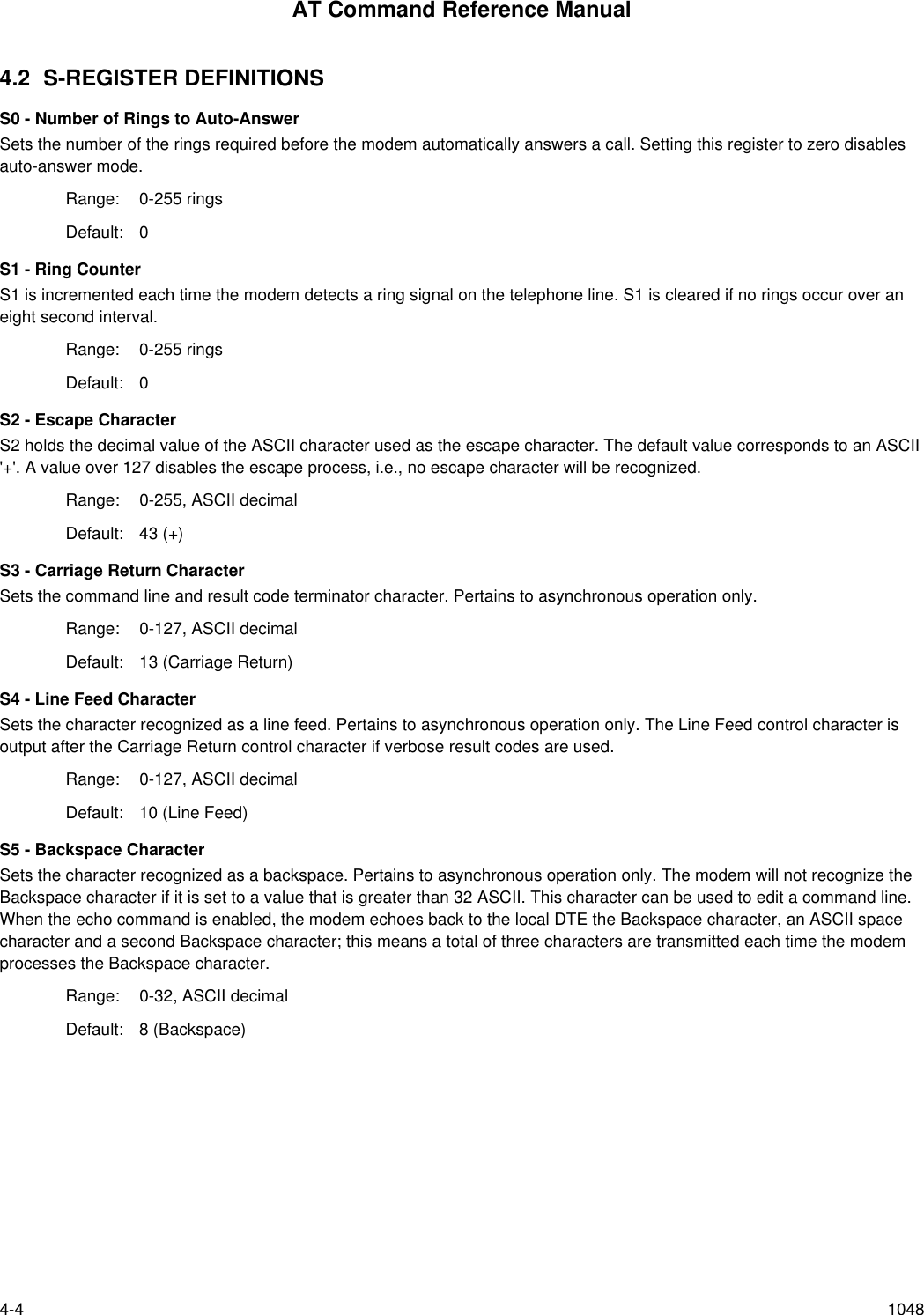
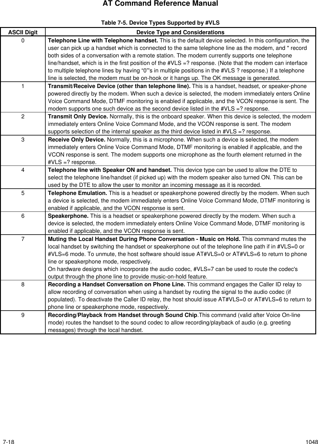
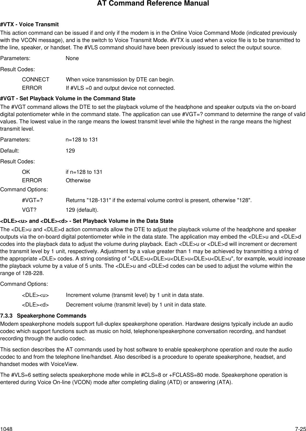
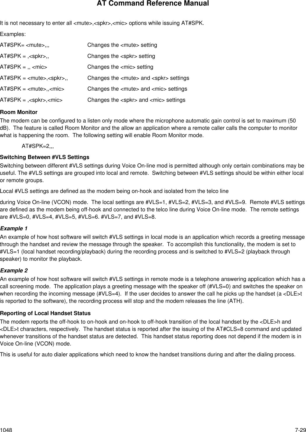
![AT Command Reference Manual1048 7-17#VLS - Voice Line SelectThis action command can be used to select which devices are routed through the modem.Parameters: n = 0-9 as supported by the modem model. [This is the device position number (not devicenumber) as reflected in response to #VLS=?]Default: 0Result Codes:OK If n = 0-9 as supported by the modem model.VCON If device selected does not connect to the telephone line. (A speaker is such a device, but atelephone line with speaker ON is not such a device, and generates OK.)ERROR If n does not equal 0-9 or if telephone line or local handset is already off-hook.Command options:#VLS? This query returns the current setting of the #VLS command as an ASCII decimal value in resultcode format.#VLS=? This query requests a report of the device types available for selection. The response is a numberfrom 0 to 4 corresponding the device position number (see Table 7-5).#VLS=0 The default option on the modem. This command instructs the modem that when entering any ofthe three voice operating submodes (Online Command, Transmit, or Receive), that the telephoneline interface should be routed through the modem. The OK response is sent to the DTE, and anyprevious connection is lost (i.e., the modem ends up on-hook as a result of issuing this commandto connect to the telephone line).#VLS=1 This command instructs the modem to route only the handset through the modem. This settingcan be chosen before recording a greeting message.#VLS=2 This command instructs the modem to route only the speaker through the modem. This settingcan be chosen before playing back any message. The modem immediately switches to OnlineVoice Command Mode, and the VCON response is generated for completeness. However, sincethis is an output only device, nothing of consequence can happen until the DTE sends the #VTXcommand.#VLS=3 This command instructs the modem that only the auxiliary input device (microphone) should berouted through the modem. This setting can be chosen before recording a greeting message.#VLS=4 This command is the same as #VLS =0, except that the modem enables the internal speaker aswell as the telephone line/handset circuit.#VLS=5 This command selects telephone emulation mode while in #CLS=8 mode. Speakerphoneoperation is entered during Voice On-line (VCON) mode after completing dialing (ATD) oranswering (ATA). #VLS=5 will respond ERROR if speakerphone is supported.#VLS=6 This command selects speakerphone mode while in #CLS=8 mode. Telephone emulationoperation is entered during Voice On-line (VCON) mode after completing dialing (ATD) oranswering (ATA). #VLS=6 will respond ERROR if speakerphone is not supported.#VLS=7 This command, valid after Voice On-line mode, mutes the local handset by switching the handsetor speakerphone out of the telephone line path if in #VLS=0 or #VLS=6 mode. To unmute, thehost software should issue AT#VLS=0 or AT#VLS=6 to return to phone line or speakerphonemode, respectively. On hardware designs which incorporate the audio codec, #VLS=7 can beused to route the codec's output through the phone line to provide music-on-hold feature.#VLS=8 (Valid after Voice On-line mode.) This command engages the Caller ID relay to allow recording ofconversation when using a handset by routing the signal to the audio codec (if populated). Todeactivate the Caller ID relay, the host should issue an AT#VLS=0 or AT#VLS=6 to return tophone line or speakerphone mode, respectively.#VLS=9 This command routes the handset to the sound codec to allow recording/playback of audio (e.g.greeting messages) through the local handset.](https://usermanual.wiki/Itron/921.Modem-User-Manual/User-Guide-100350-Page-149.png)
![AT Command Reference Manual7-20 1048#VSD - Enable Silence Deletion (Voice Receive) [ADPCM]This command provides no function other than command response compatibility.Parameters: n = 0 or 1Default: 0Result Code:OK If n = 0 or 1.ERROR Otherwise.Command options:#VSD? Returns the current setting of the #VSD command as an ASCII decimal value in result codeformat.#VSD=? Returns the message, “0,1”.#VSD=0 Command provides no function other than command response compatibility.#VSD=1 Command provides no function other than command response compatibility.#VSK - Buffer Skid SettingThis command queries and sets the number of bytes of spare space, after the XOFF threshold is reached, in the modem'sbuffer during Voice Transmit Mode. This equates to the “skid” spare buffer space, or the amount of data the DTE cancontinue to send after being told to stop sending data by the modem, before the modem voice transmit buffer overflows.Parameter: n = 255 (Number of bytes of “skid spare buffer space)Default: 255Result Code:OK If n = 255.ERROR Otherwise.Command options:#VSK? Returns the current setting of the #VSK command as an ASCII decimal value in result codeformat.#VSK=? Returns the message, “255”.](https://usermanual.wiki/Itron/921.Modem-User-Manual/User-Guide-100350-Page-152.png)
![AT Command Reference Manual1048 7-21#VSP - Silence Detection Period (Voice Receive) [ADPCM]This command sets the Voice Receive Mode silence detection period (inactivity timer) value. The parameter, in units of 100ms, can be used when receiving voice data. This is an amount of time, which if elapsed without receiving any ADPCM data,causes the modem to send the <DLE>s or <DLE>q codes after insuring that the buffer is empty.The modem determines what constitutes silence. This involves monitoring and debouncing the modem value for averageenergy. If this debounced value is less than an arbitrary threshold constituting the modem's definition of silence for a periodgreater than that defined by the #VSP setting, the modem sends the <DLE>q or <DLE>s shielded code to the DTE.Parameters: n = 0 – 255 (0 – 25.5 seconds)Default: 55Result Code:OK If n = 0 – 255.ERROR Otherwise.Command options:#VSP? Returns the current setting of the #VSP command as an ASCII decimal value in result codeformat.#VSP=? Returns the message, “0-255”.#VSP=0 Turns off the silence period detection timer.#VSP=n Where n defines the period without received voice data in 100 ms units.#VSR - Sampling Rate SelectionThis parameter, along with the bits per sample (#VBS) command, determines the necessary DTE interface speed to transmitand receive in Voice/Audio Mode.Parameters: n=7200 (7200 Hz sampling rate for ADPCM or PCM), orn=11025 (11.025 kHz sampling rate for PCM only)Default: 7200Result Codes:OK If n=7200, or if n=11025 and #VBS=8ERROR OtherwiseCommand options:#VSR? Returns the current setting of the #VSR command as an ASCII decimal value in result codeformat.#VSR=? Returns the message "7200, 11025"#VSR=7200 Selects 7200 Hz sampling rate#VSR=11025 Selects 11.025 kHz sampling rate](https://usermanual.wiki/Itron/921.Modem-User-Manual/User-Guide-100350-Page-153.png)
![AT Command Reference Manual7-22 1048#VSS - Silence Detection Tuner (Voice Receive) [ADPCM]This command enables or disables the Voice Receive mode silence detection, and controls the sensitivity employed by themodem in ADPCM compressing periods of silence.Parameters: n = 0 – 3Default: 0Result Codes:OK If n = 0 – 3.ERROR Otherwise.Command options:#VSS? Returns the current setting of the #VSS command as an ASCII decimal value in result codeformat.#VSS=? Returns the message “0,1,2,3".#VSS =0 Disables silence detection by the modem when in Voice Receive Mode (default).#VSS =1 Least sensitive setting. When this command is received by the modem, the system is configuredto a state which is least likely to detect and compress periods of silence, but still able to do so ifthe line is really quiet.#VSS =2 Midrange setting. When this command is received by the modem, the system is configured to astate which is likely to be the best overall compromise on normal telephone lines.#VSS =3 Most sensitive setting. When this command is received by the modem, the system is configuredto a state which is most likely to detect and compress periods of silence.](https://usermanual.wiki/Itron/921.Modem-User-Manual/User-Guide-100350-Page-154.png)
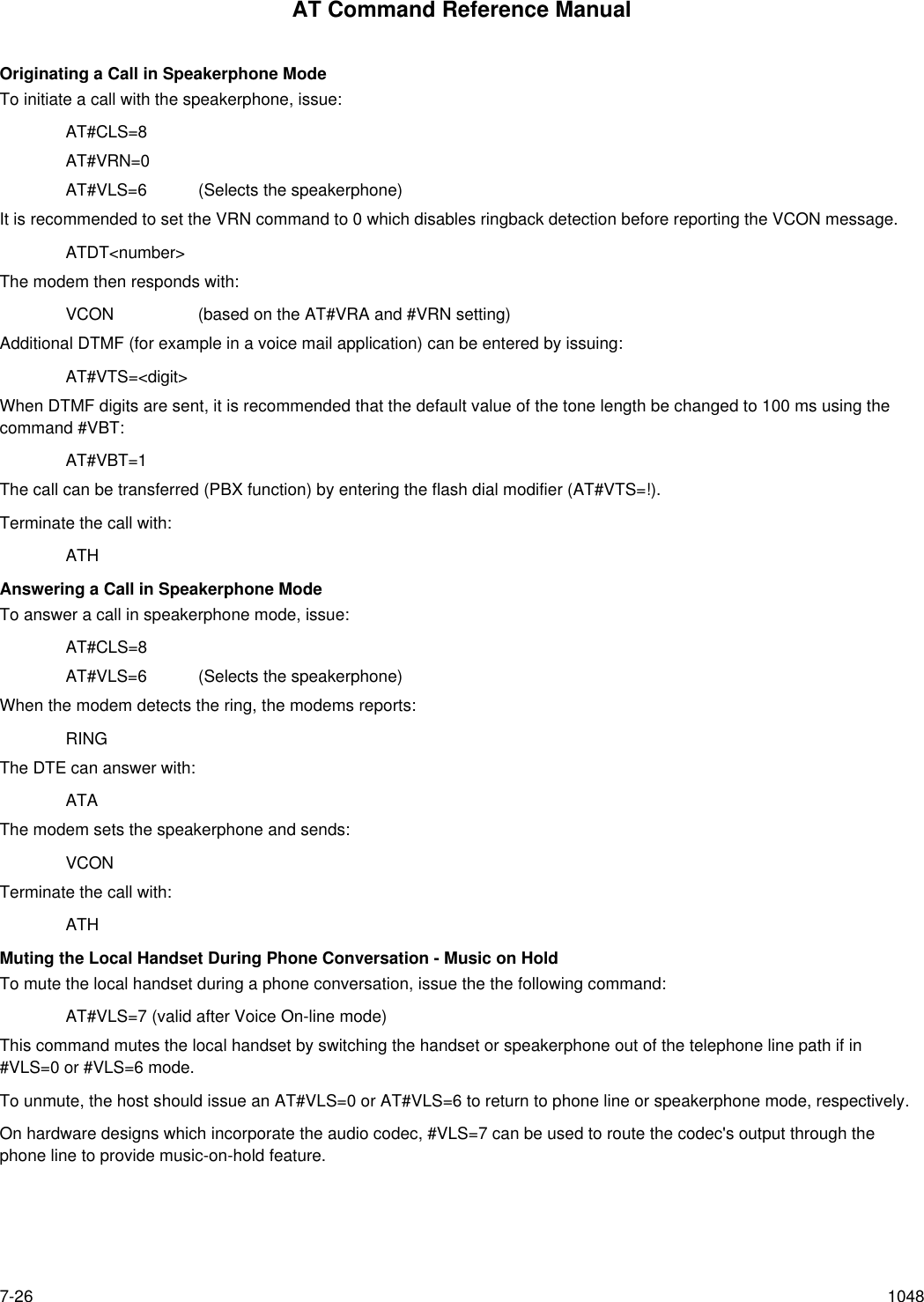
![AT Command Reference Manual7-24 1048#VTM - Enable Timing Mark PlacementThis command controls the placement of <DLE><T> timing marks by the DCE in the data stream during ADPCM recording.Parameters: n=0 (disabled) or 10 (1 second interval)Default: n=0 (disabled)Result Codes:OK If n=0 or 10ERROR OtherwiseCommand Options:#VTM? Returns the current setting of the #VTM command as an ASCII decimal value in result codeformat.#VTM=? Returns "0, 10"#VTS - Generate Tone Signals (Online Voice Command)This action command can be issued to play one of more DTMF or other tones (such as a “beep") if and only if the modem isin the Online Voice Command Mode and the sampling rate (see the #VSR command) is set to 7.2 kHz. The modem parsesand plays the tones defined in the parameter in the order listed, and no key abort is accepted. The parameter can havethree types of elements separated by commas, and following "#VTS=":Dual or Single Tones with Variable Duration: These are represented by the substring [x,y,z] (enclosed in squarebrackets, "[ ]", as shown) in the parameter field. Each such substring consists of three sub-elements corresponding to the two frequencies (i.e., x and y), and the duration (i.e., z).[x,y,z] x represents the first frequency (0 or 200-3000 Hz)y represents second frequency (0 or 200-3000 Hz)z represents the duration (which is ASCII decimal in units of 100 ms)DTMF Digits with Variable Duration. This is represented by a substring {x,z} (enclosed in curly braces, "{}", asshown) in the parameter field. Each such substring consists of two sub-elementscorresponding to a DTMF digit (i.e., x) and the duration (i.e., z).{x,z} x represents the DTMF digit (0-9,A-D,*,#)z represents the duration (which is ASCII decimal in units of 100 ms)DTMF Digits, with duration defined by #VBT. This is represented by a value x (non-bracketed) corresponding to aDTMF digit (i.e., x) in the parameter field.x x represents the DTMF digit (0-9,A-D,*,#), with the duration defined by #VBTCommand options:#VTS=[x,y,z], {x,z}, and/or x, as described above.Parameters: The tone generation consists of elements in a list with each element separated by commas.Result Codes:OK Command to play tones on currently selected device is accepted.ERROR Command was not issued during Online Voice Command Mode or string is grammaticallyincorrect.](https://usermanual.wiki/Itron/921.Modem-User-Manual/User-Guide-100350-Page-156.png)
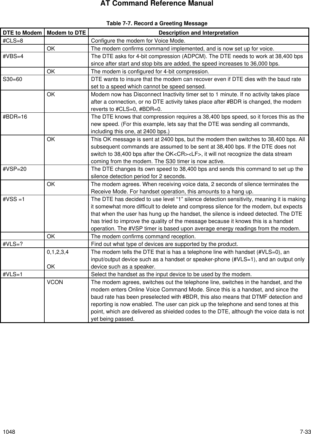
![AT Command Reference Manual7-34 1048 Table 7-7. Record a Greeting Message [Cont’d]DTE to Modem Modem to DTE Description and Interpretation#VRX This tells the modem that the DTE is ready to receive a voice message at the currentcompression/sampling settings.CONNECT The modem tells the DTE that it can now expect data. The modem enters VoiceReceive Mode. DTMF monitoring is still enabled as well as ADPCM data flow.<Data> User says: “Hello, this is me, press * to skip this message. I'm happy that you havecalled, so press 5 to send your fax, or you can leave your message at the beep.” Userthen hangs up, the message is buffered to the DTE, and the DTE waits for themessage to end. The DTE should have some kind of maximum timer running to ensurethat the user won't speak longer than some predetermined limit. Alternatively, the DTEcan require the user to enter a DTMF tone to terminate transmission of the message tothe DTE.<DLE>q The modem has noticed (#VSP time out) that the user has finished. The modemreports this while staying in Voice Receive Mode. DTMF detection and reporting is stillactive. The DTE now has the entire greeting message on disk.<DLE>* The user has inadvertently pressed the “*” button, but the DTE is not interested in thispresently.! The DTE issues a key abort to switch to Online Voice Command Mode.<DLE><ETX>VCONThe modem exits Voice Receive Mode and switches to Online Voice Command Mode.#VLS=0 The DTE did not really have to do this, but wants to make sure that it gets no moreDTMF codes from the handset. Selection of the telephone line here forces the modemout of Online Voice Command Mode, which is equivalent to hanging up.OK](https://usermanual.wiki/Itron/921.Modem-User-Manual/User-Guide-100350-Page-166.png)
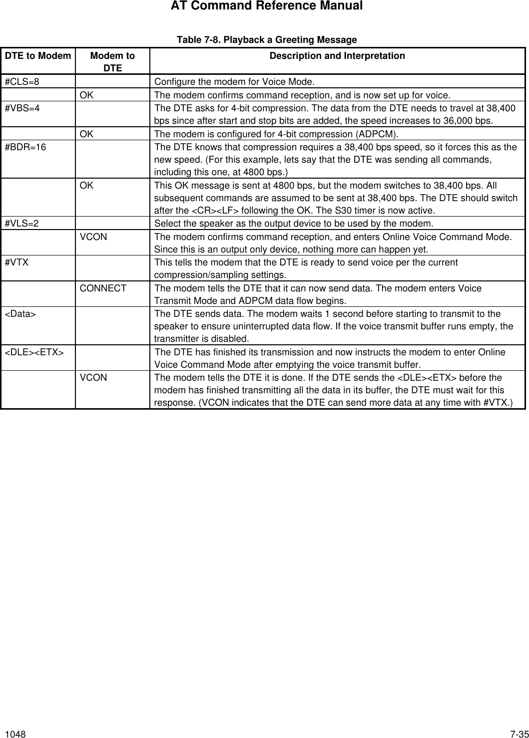

![AT Command Reference Manual1048 7-37 Table 7-9. Answer Call/Play Greeting/Record Message [Cont’d]DTE to Modem Modem to DTE Description and Interpretation#VTX The DTE does not wait for any tones, and tells the modem that it is ready to send avoice greeting at the current compression and sampling settings (4-bit/7200).CONNECT The modem tells the DTE that it can now send data. The modem enters VoiceTransmit Mode and DTMF monitoring is still enabled as well as the ADPCM data flow.<Data> The DTE sends greeting message data. The modem waits up to 1 second or untilXOFF threshold is reached before starting to transmit to ensure uninterrupted dataflow. If the voice transmit buffer runs empty, the transmission is disabled.<DLE><ETX> The DTE has finished with its transmission, and now instructs the modem to enterOnline Voice Command Mode since this is the telephone line.VCON The modem tells the DTE it is done. If the DTE sends the <DLE><ETX> before themodem has finished transmitting all the data in its voice transmit buffer, the DTE mustwait for this response.#VBT=12 The DTE requests that DTMF digits be sent as “beeps” with the #VTS command whilein Online Voice Command Mode, with each “beep” having a duration of 1.2 seconds.OK The modem confirms command reception#VTS=# The DTE sends a “BEEP” to annotate its greeting message. This beep is a 1.2 secondlong DTMF #. During this period, the no abort is possible from the DTE, and should notbe necessary.OK After the modem sends the “BEEP”, it sends OK to inform the DTE that it is ready tomove on. DTMF pass through is re-enabled.#VBS=4 The DTE asks for 4-bit compression to recorded message. The DTE needs to work at38,400 bps since after start and stop bits are added the speed increases to 36,000bps.OK The modem is configured for 4-bit compression.#VRX The DTE instructs the modem to turn the line around and begin recording a messagefrom the remote.CONNECT The modem sets things up and enables ADPCM data transfer to the DTE with thecurrent silence detection sensitivity setting.<Data> ADPCM data is shipped to the DTE with shielded DTMF tones folded in. The modem islooking for silence, busy, dial tone, and loop break. The DTE records everything in itsstorage media.<DLE>b The caller has finished, hung up, and in this case, a busy cadence was detected beforeanything else such as expiration of the #VSP silence detection period.X The DTE uses a key abort to respond to a busy detection.<DLE><ETX>VCONThe modem is now in Online Voice Command Mode.H DTE sends modem to #CLS=0 with #BDR=0.](https://usermanual.wiki/Itron/921.Modem-User-Manual/User-Guide-100350-Page-169.png)
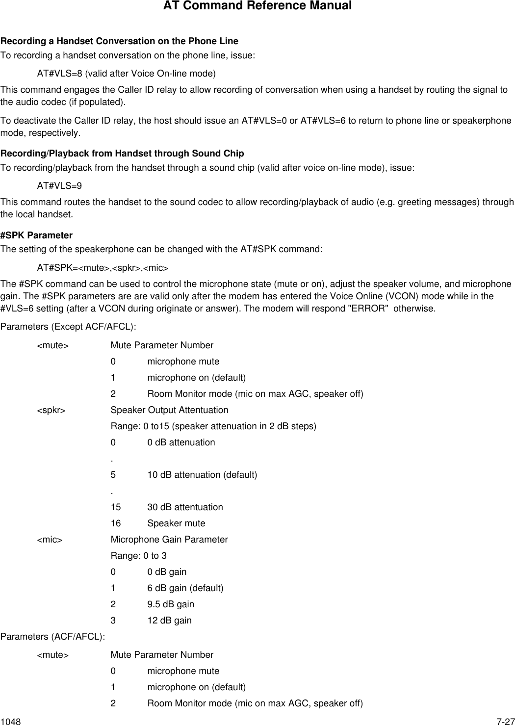
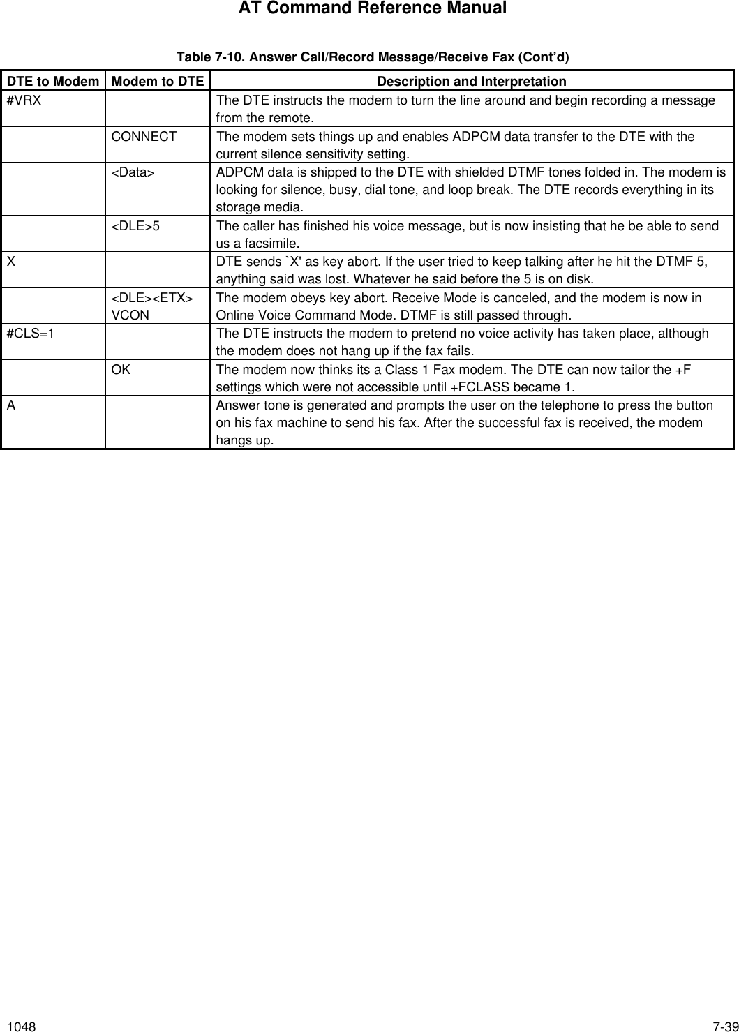
![AT Command Reference Manual7-38 1048 Table 7-10. Call/Record Message/Receive FaxDTE to Modem Modem to DTE Description and Interpretation#CLS=8 Configure the modem for Voice Mode.OK The modem agrees, and is now set up for voice.#VBS=4 The DTE asks for 4-bit compression (ADPCM). The DTE needs to work at 38,400 bpssince after start and stop bits are added the speed increases to 36,000 bps.OK The modem is configured for 4-bit compression.#VSS=2 Sets silence detection sensitivity to midrange.OK The modem confirms command reception.#VLS=0 This selects the telephone line, and ensures that it is on-hook.OK The modem confirms command reception, and switches in the telephone line.#CLS=8 This ensure things are set up for voice.OK The modem confirms command reception, and is now set up for voice.RING Sometime later, the next call is received. The modem answers.#BDR=16 The DTE knows that compression requires a 38,400 bps speed, so it forces this as thenew speed. (For this example, lets say that the DTE was sending all commands,including this one, at 9600 bps.)OK This OK message is sent at 9600 bps, but the modem then switches to 38,400 bps. Allsubsequent commands are assumed to be sent at 38,400 bps. The S30 timer is nowactive.A The DTE answers.VCON The modem is now in Online Voice Command Mode. DTMF and calling tone detectionis enabled.#VTX The DTE does not wait for any tones, and tells the modem that it is ready to send avoice greeting at the current compression and sampling settings.CONNECT The modem tells the DTE that it can now send data. The modem enters VoiceTransmit Mode and DTMF monitoring is still enabled as well as ADPCM data flow.<Data> The DTE sends greeting message data. The modem waits 1 second before starting totransmit to ensure uninterrupted data flow. If the voice transmit buffer runs empty, thetransmission is disabled.<DLE><ETX> The DTE has finished its transmission and now instructs the modem to enter OnlineVoice Command Mode.VCON The modem tells the DTE it is done. If the DTE sends the <DLE><ETX> before themodem has finished transmitting all the data in its voice transmit buffer, this responseis delayed until the buffer is empty.#VBT=13 The DTE requests that DTMF digits be dialed as “beeps” while in Online VoiceCommand Mode, with each “beep” having a duration of 1.3 seconds.OK The modem agrees.#VTS=[1000,0,20],9,The DTE sends a “BEEP” to annotate its greeting message. This beep is a 2 secondlong 1000 Hz tone, followed by a 1.3 second long DTMF 9. During this period, the DTEis locked out.OK After the modem sends the “BEEP”, it sends OK to inform the DTE that it is ready tomove on. DTMF pass through is re-enabled.](https://usermanual.wiki/Itron/921.Modem-User-Manual/User-Guide-100350-Page-170.png)
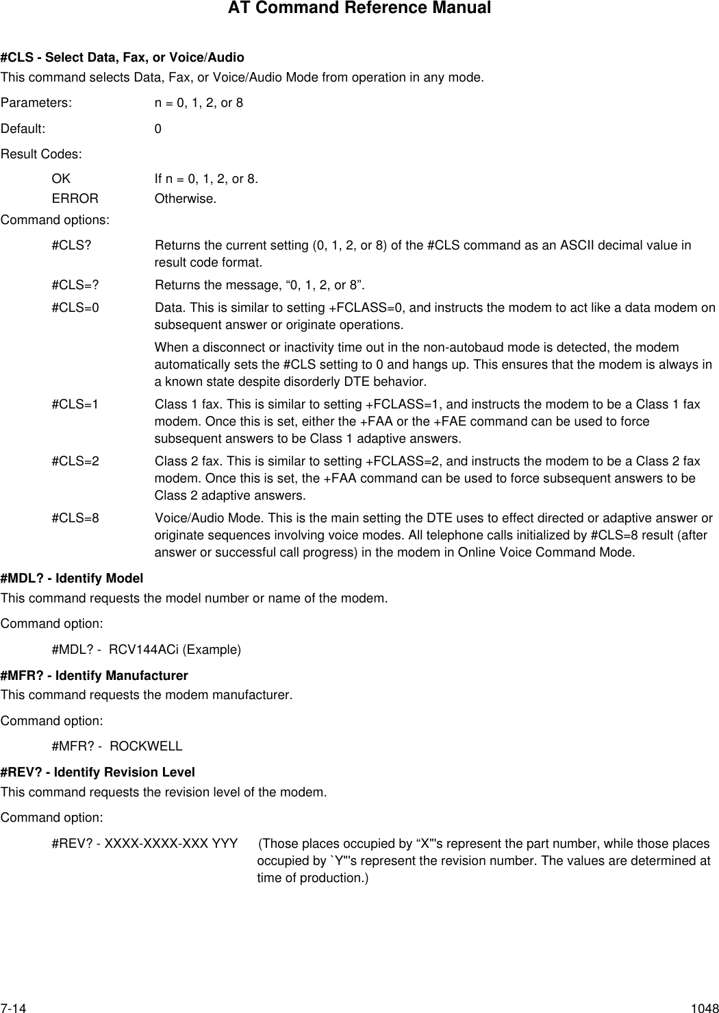
![AT Command Reference Manual1048 8-58.3 MNP 10 COMMANDS-K0 Disable MNP 10 extended services.-K1 Enable MNP 10 extended services.-K2 Enable MNP 10 extended services detection only.-SEC=0 Disable MNP10-EC.-SEC=1,[<tx level>] Enable MNP10-EC and set transmit level <tx level> 0 to 30 (0 dBm to -30 dBm).8.4 W-CLASS COMMANDS*B Display list of permanently blacklisted numbers.*D Display list of delayed numbers.*NCn Change country to one of eight in NVRAM.8.5 CALLER ID COMMANDS#CID=0 Disable Caller ID.#CID=1 Enable Caller ID with formatted presentation.#CID=2 Enable Caller ID with unformatted presentation.8.6 FAX CLASS 1+FCLASS=n Service class.+FAE=n Data/fax auto answer+FRH=n Receive data with HDLC framing.+FRM=n Receive data.+FRS=n Receive silence.+FTH=n Transmit data with HDLC framing.+FTM=n Transmit data.+FTS=n Stop transmission and wait.](https://usermanual.wiki/Itron/921.Modem-User-Manual/User-Guide-100350-Page-179.png)