Itron 24GZB Automatic Meter Reading Device for Gas Meters User Manual 2 4GZ OpenWay Gas Module Installation Guide
Itron, Inc. Automatic Meter Reading Device for Gas Meters 2 4GZ OpenWay Gas Module Installation Guide
Itron >
Contents
- 1. Users Manual Part 1
- 2. Users Manual Part 2
- 3. Users Manual Part 3
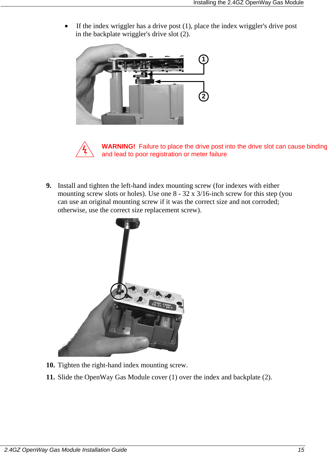
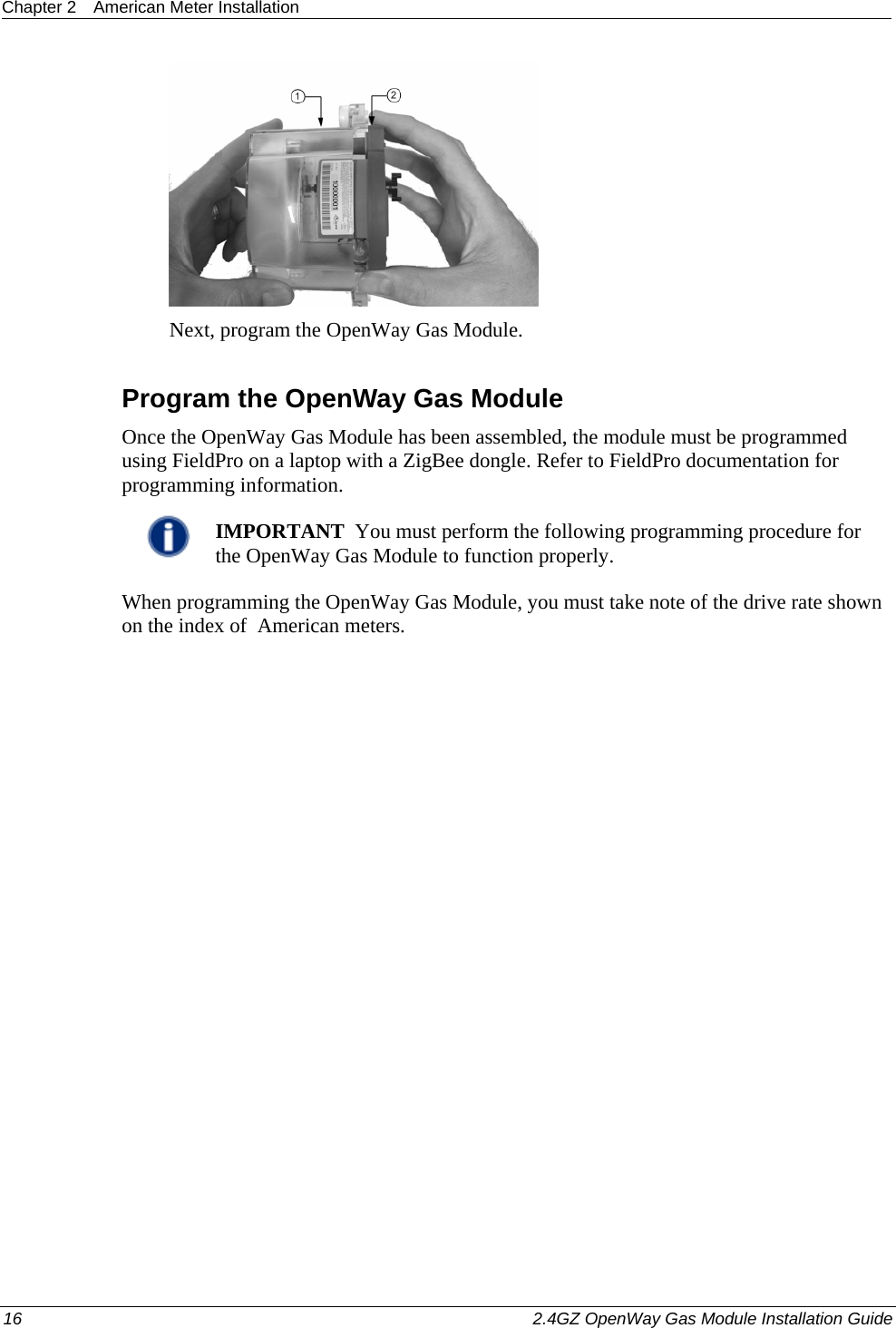
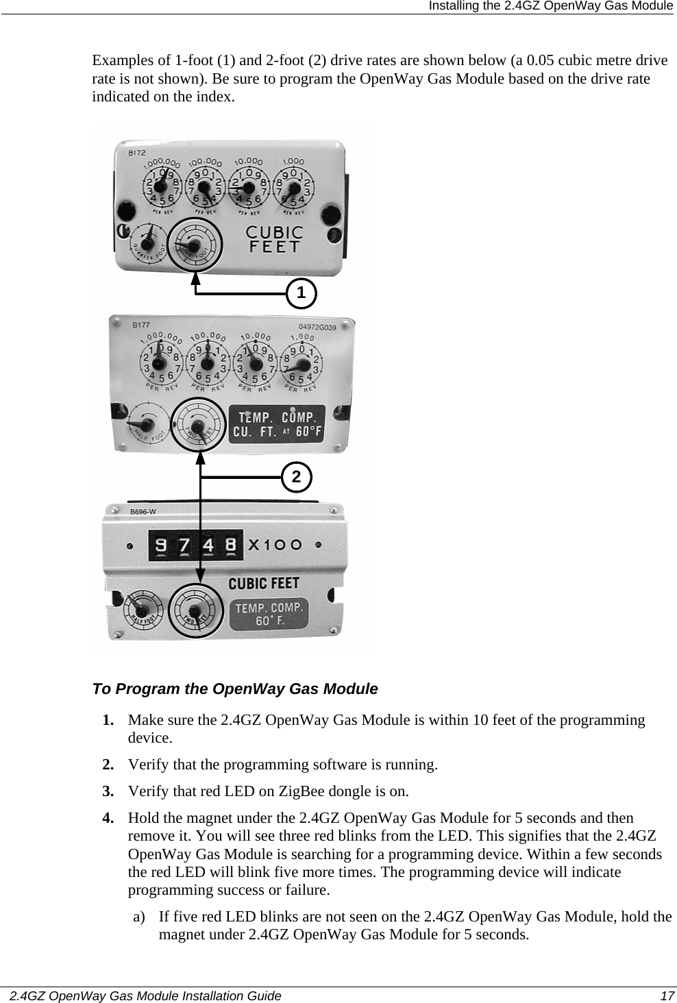
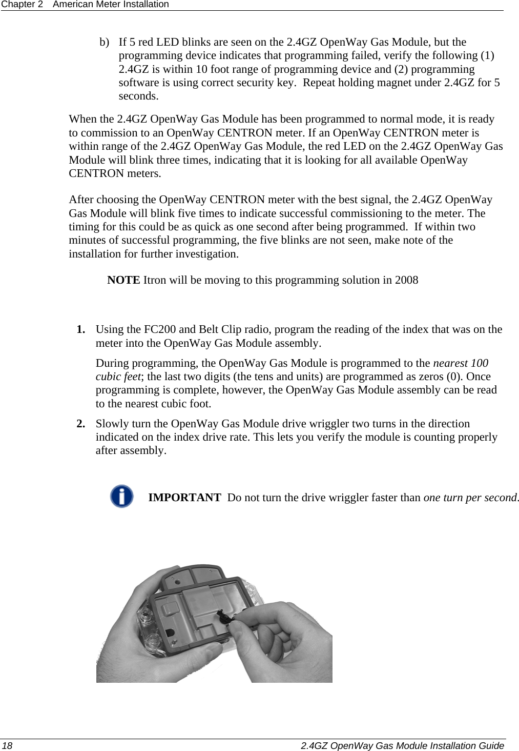
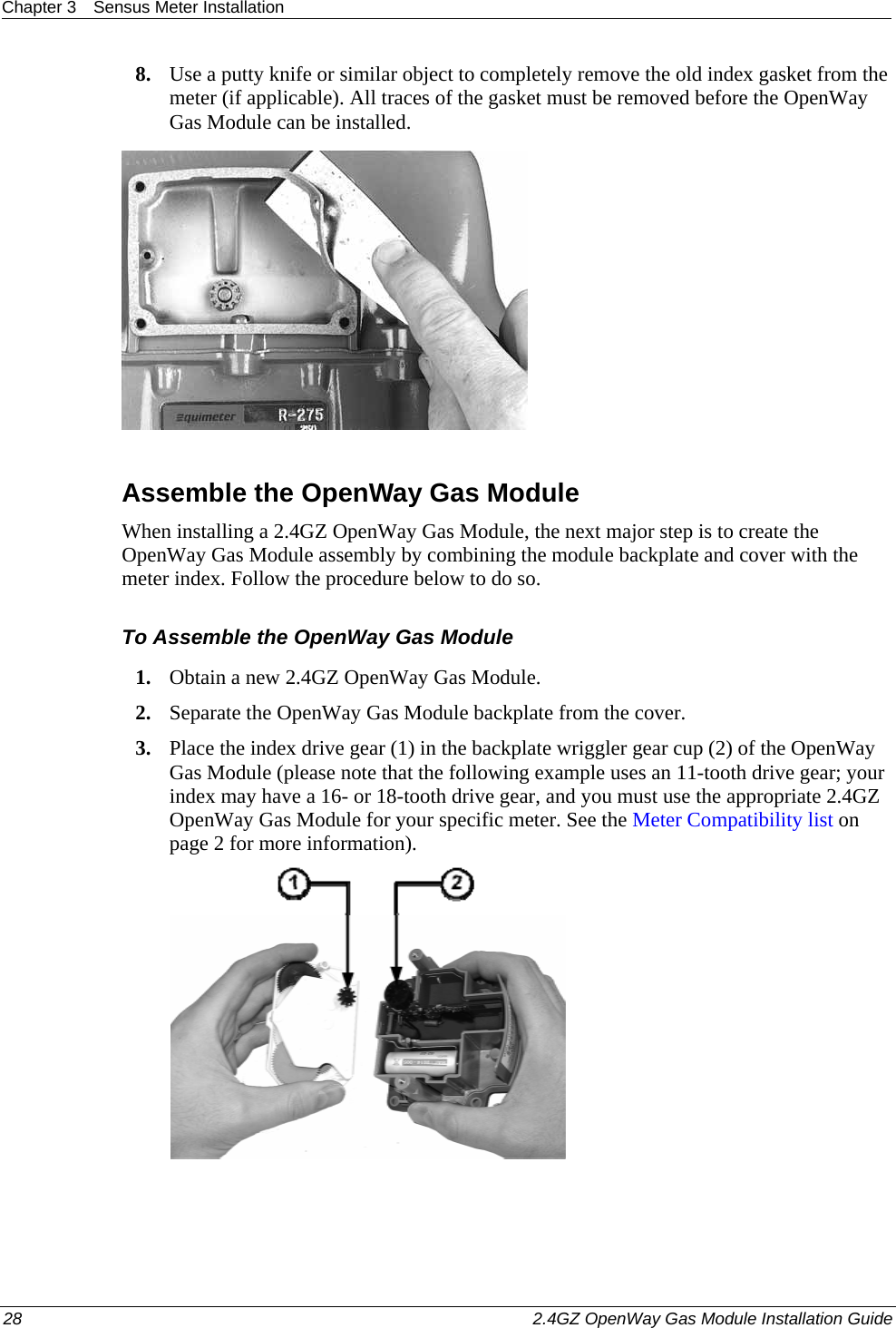
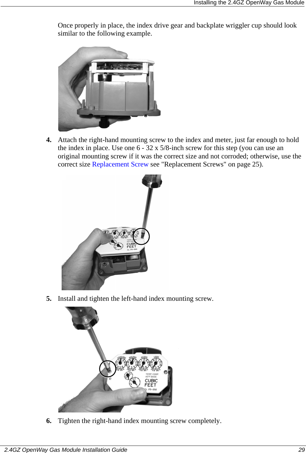
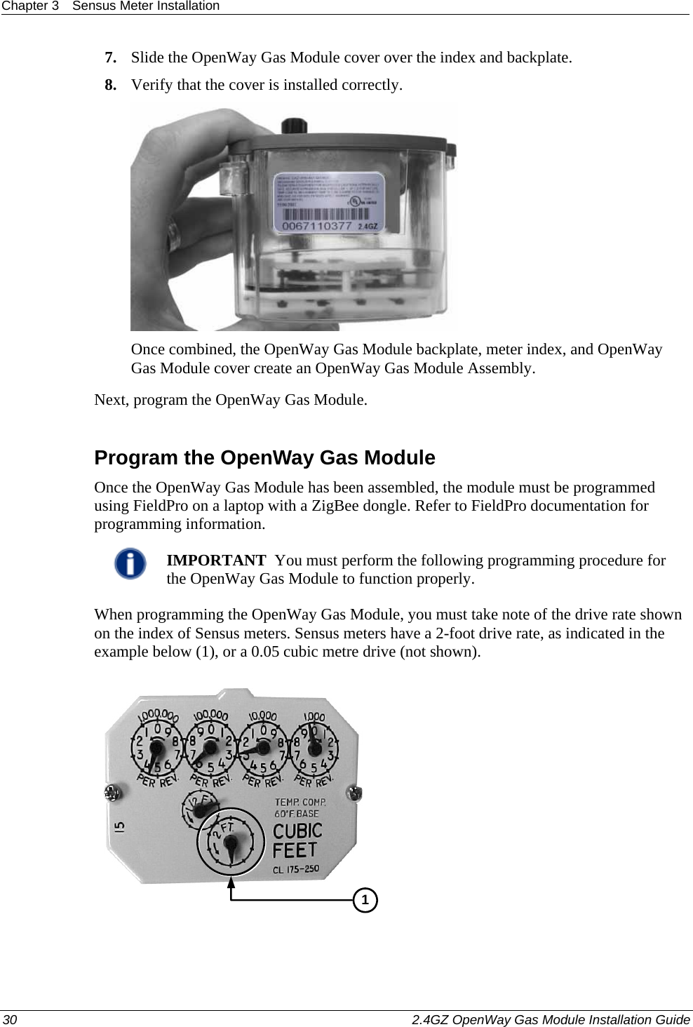
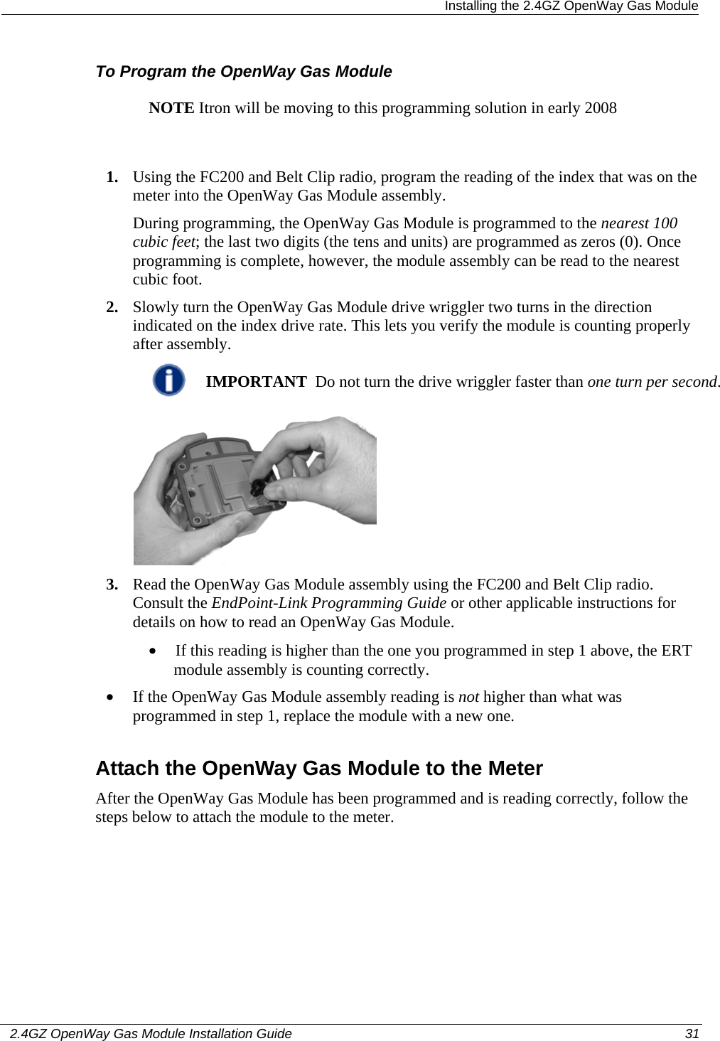
Users Manual Part 2