Itron 100GDLRS AMR transceiver device for utility meters User Manual
Itron Inc AMR transceiver device for utility meters Users Manual
UserManual.wiki
>
Itron
>
100GDLRS User Manual
>
Users Manual
Contents
1.
Users Manual 1
2.
Users Manual 2
3.
Users Manual 3
4.
Users Guide 1
5.
Users Guide 2
6.
Users Guide 3
7.
Users Manual
Users Manual
Navigation menu
Upload a User Manual
Namespaces
Wiki Guide
HTML
PDF
Info
Views
User Manual
Discussion / Help
Navigation

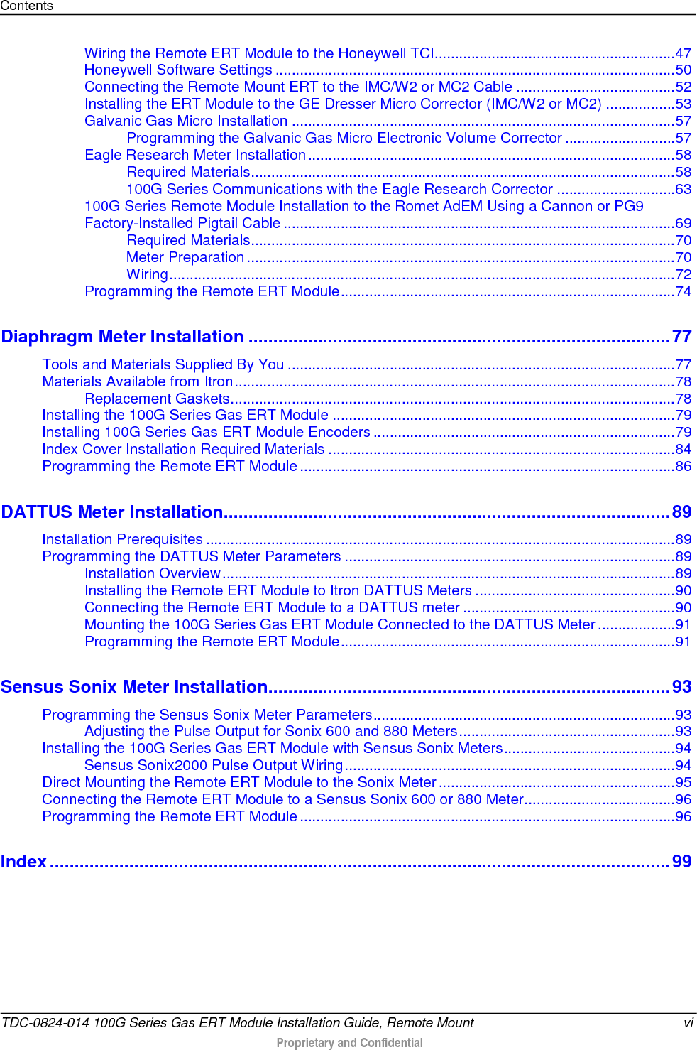


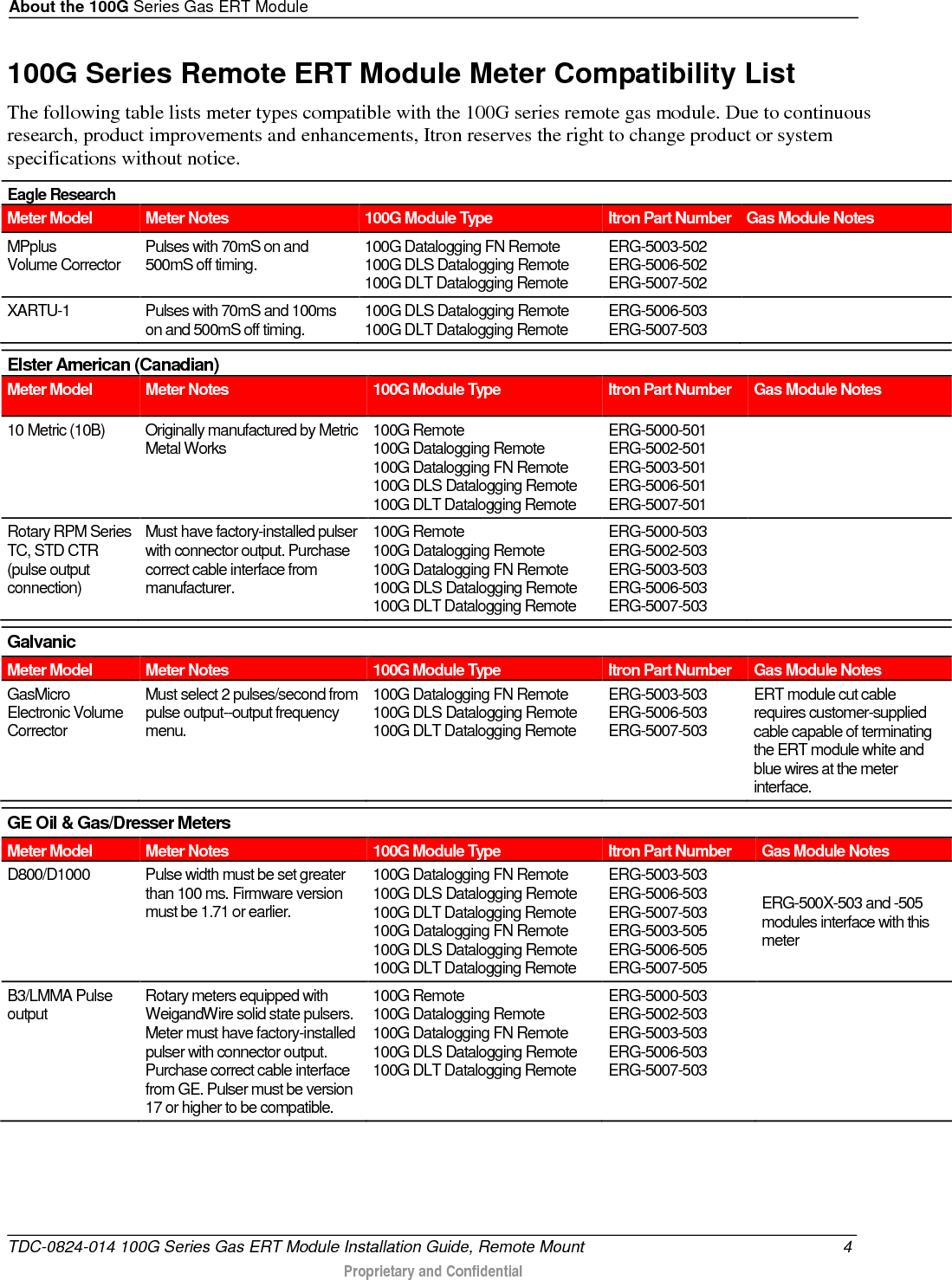
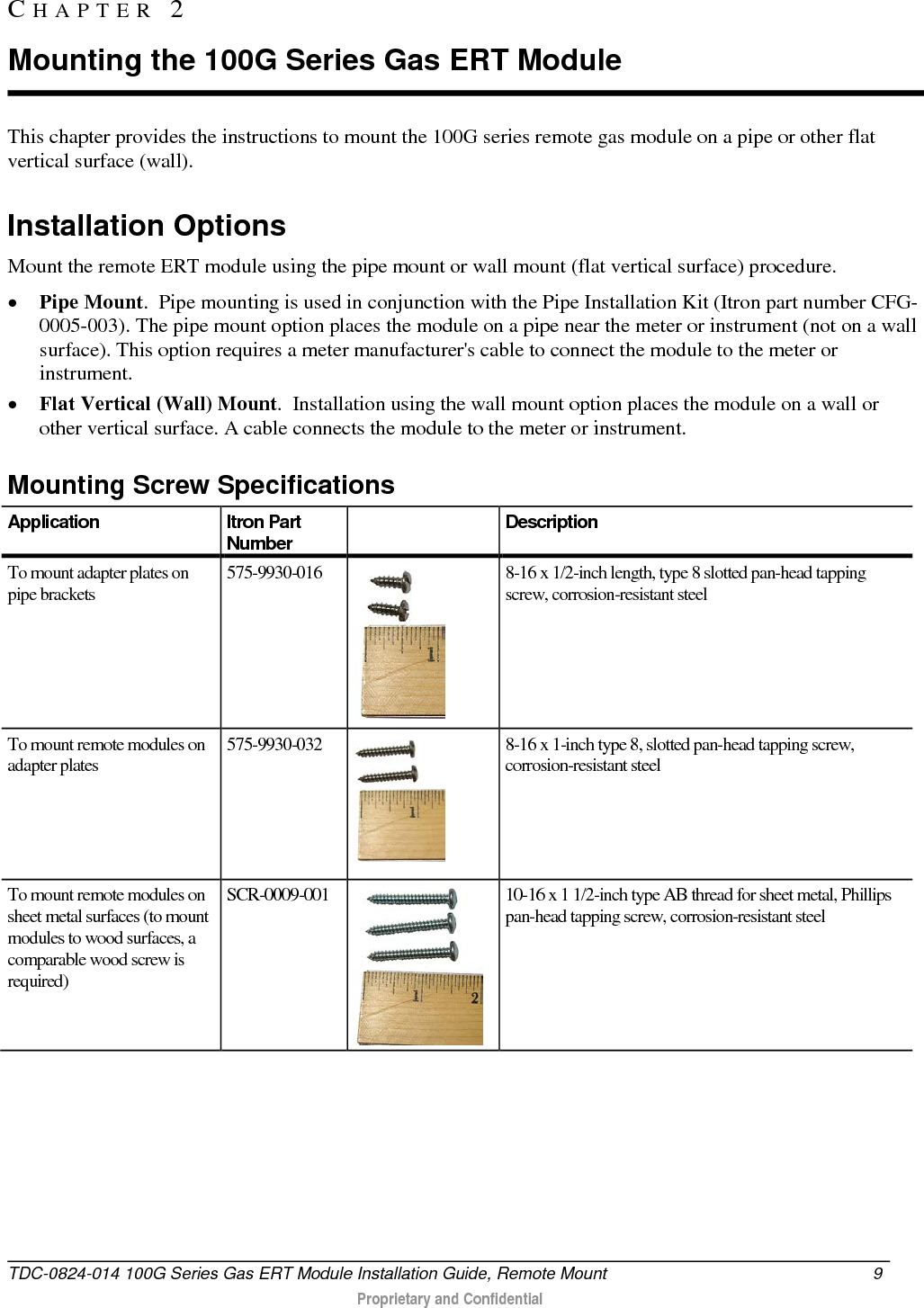
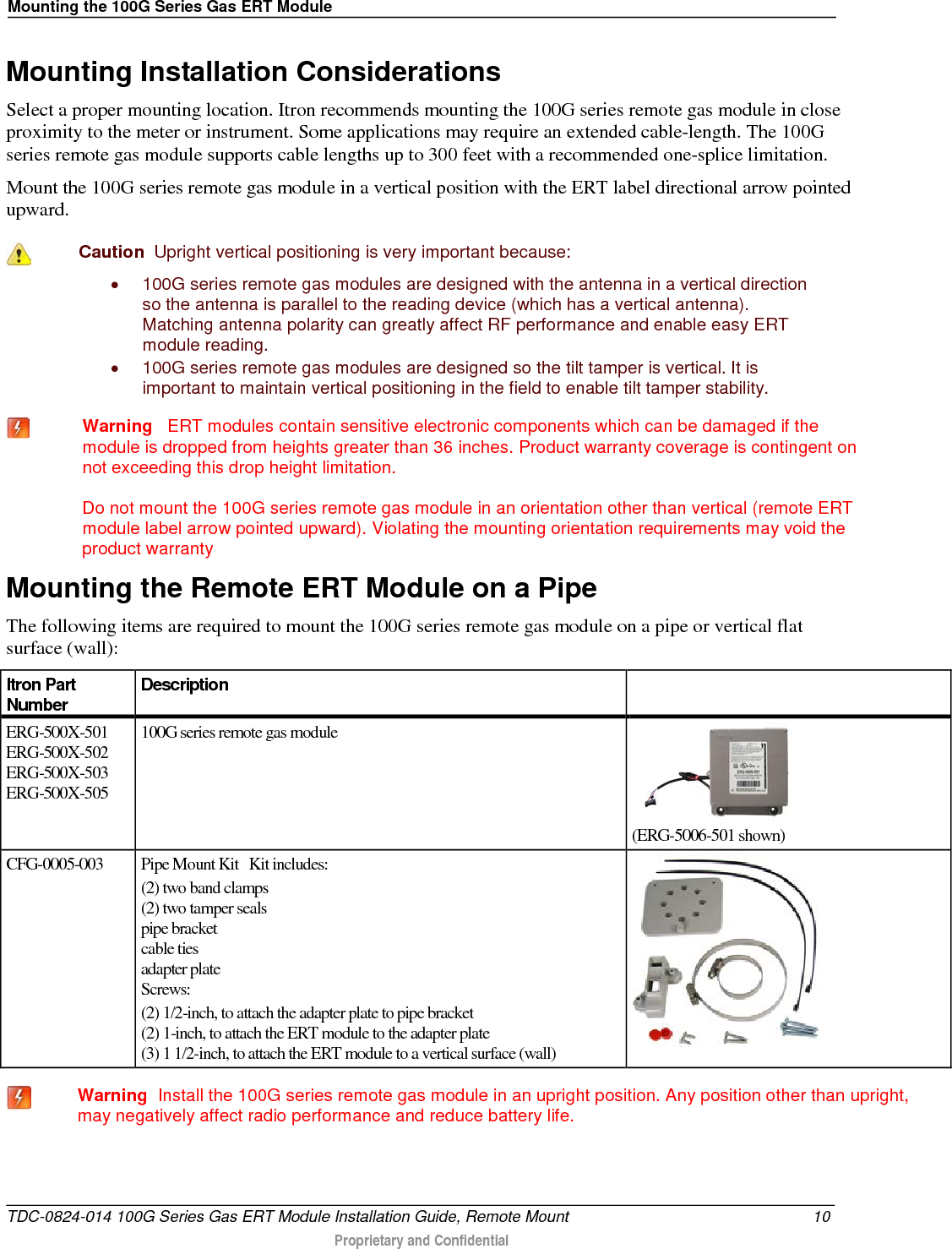
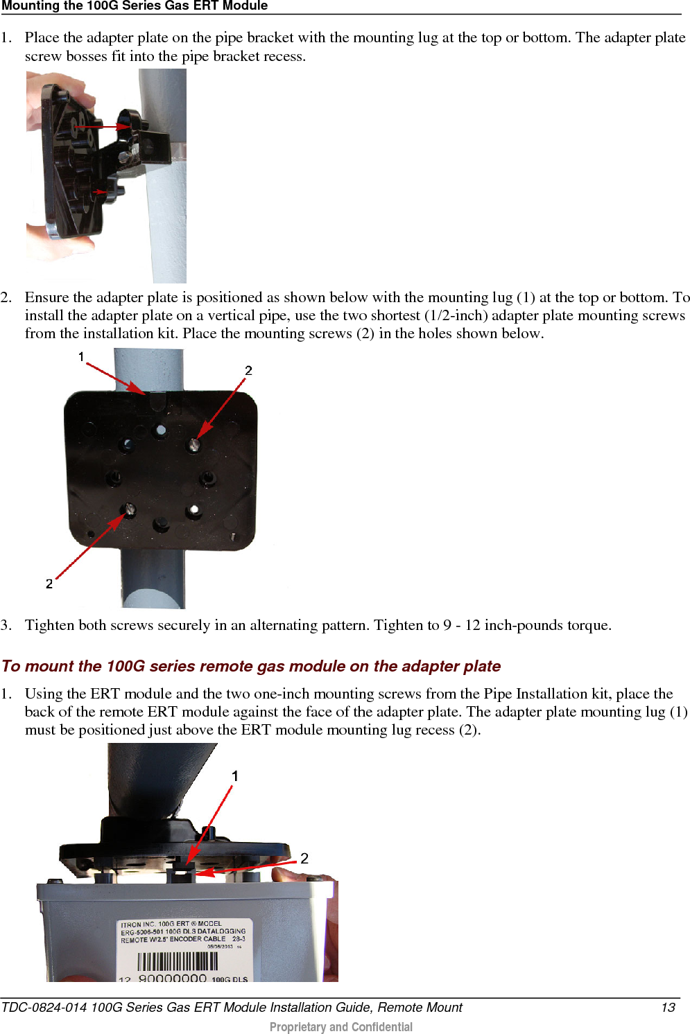
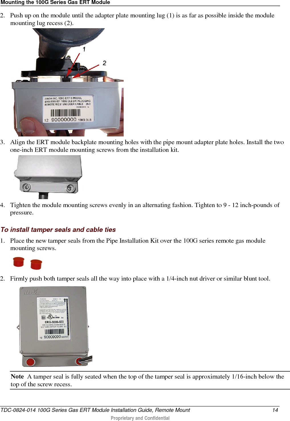
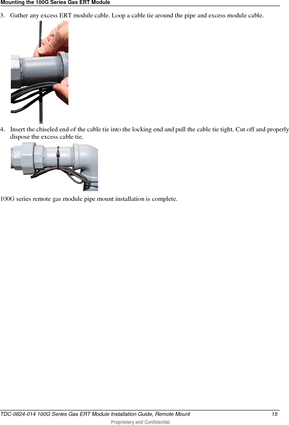
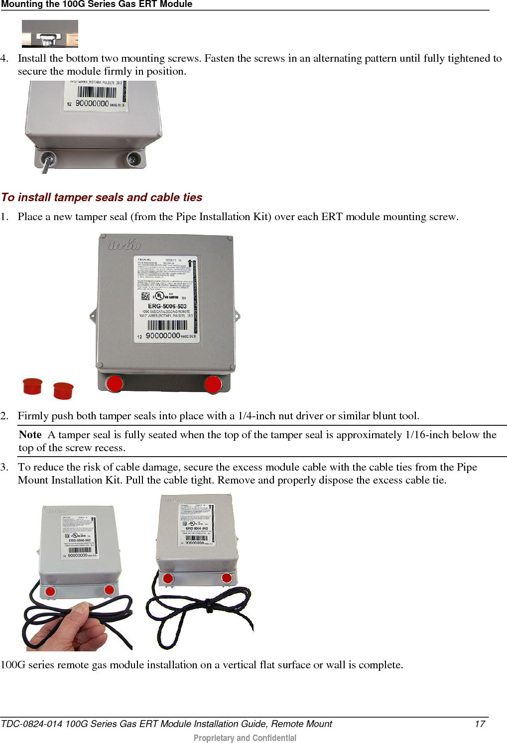
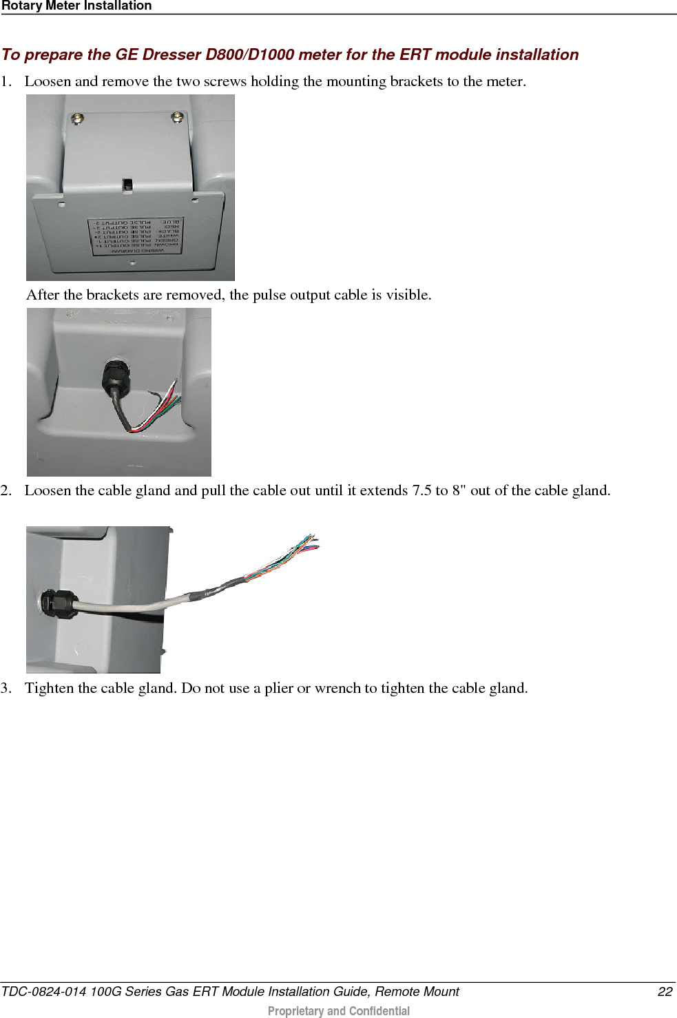
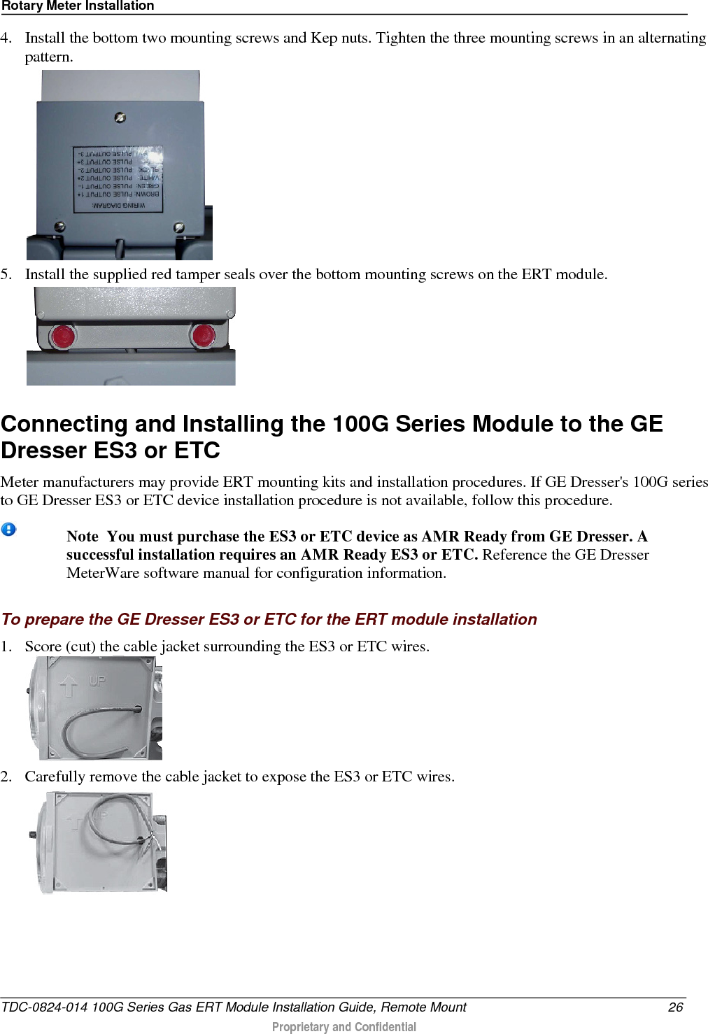
![Mounting the 100G Series Gas ERT Module Mounting the Remote Gas Module on a Wall or Other Flat Vertical Surface Carefully select a mounting location free from electrical wires. The mounting location must have the proper clearance to accommodate the 1-1/2-inch module mounting screws so nothing is damaged by the drill or mounting screws. Note For easier installation, drill three pilot holes in the mounting surface (use the correct size drill bit to accommodate the module mounting screws [see the drilling template below]). The drilled pilot holes for the two bottom screws must be on a horizontal line. To mount the module on a sheet metal surface, use the mounting screws included with the Remote Mounting kit. Use a comparable wood screw to mount the module on a vertical wood surface. Remote module drilling template A 3 inches B 1-11/16 inches C 3-3/8 inches To mount the remote gas module on a wall or other flat vertical surface 1. Using one of the three 1-1/2-inch mounting screws from the Pipe Mount Kit, turn the mounting screw for the mounting lug (top of module) part way into the mounting surface. 2. Place the 100G series remote gas module mounting lug recess (on the top of the module backplate) just under the screw head. 3. Slide the module upward until the screw head fits completely inside the mounting lug recess. Several adjustments may be necessary to properly position the screw for module mounting. TDC-0824-014 100G Series Gas ERT Module Installation Guide, Remote Mount 16 Proprietary and Confidential](https://usermanual.wiki/Itron/100GDLRS.Users-Manual/User-Guide-3396481-Page-24.png)