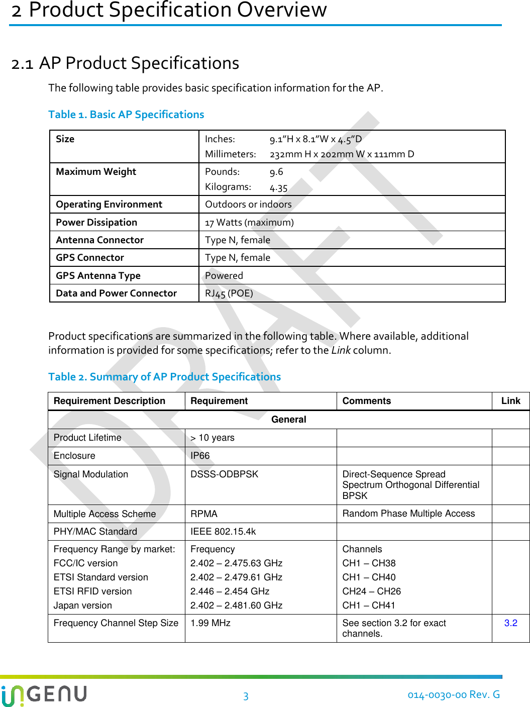
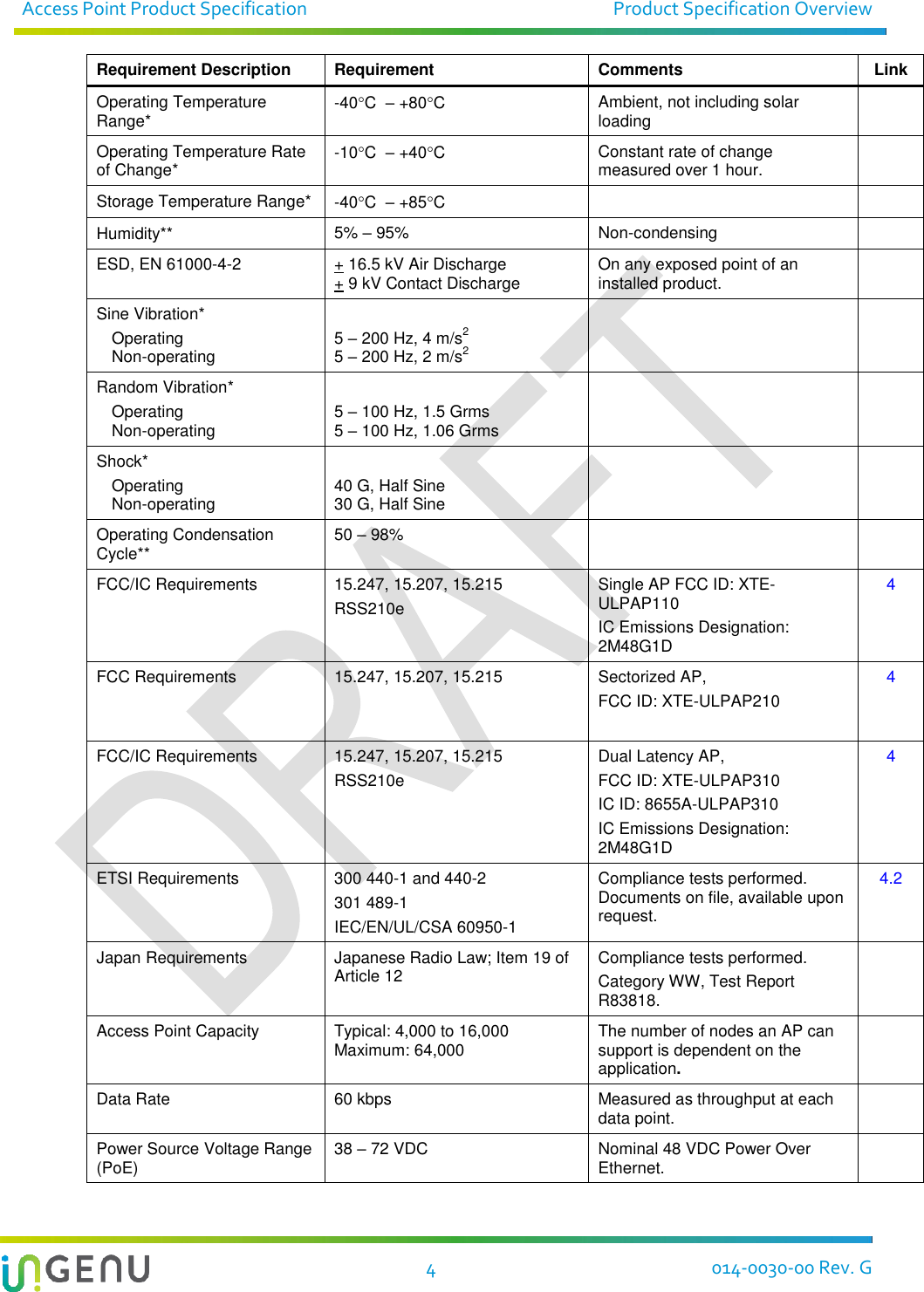
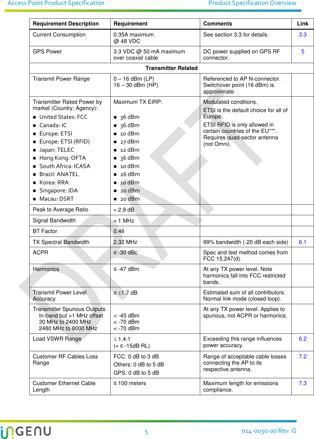
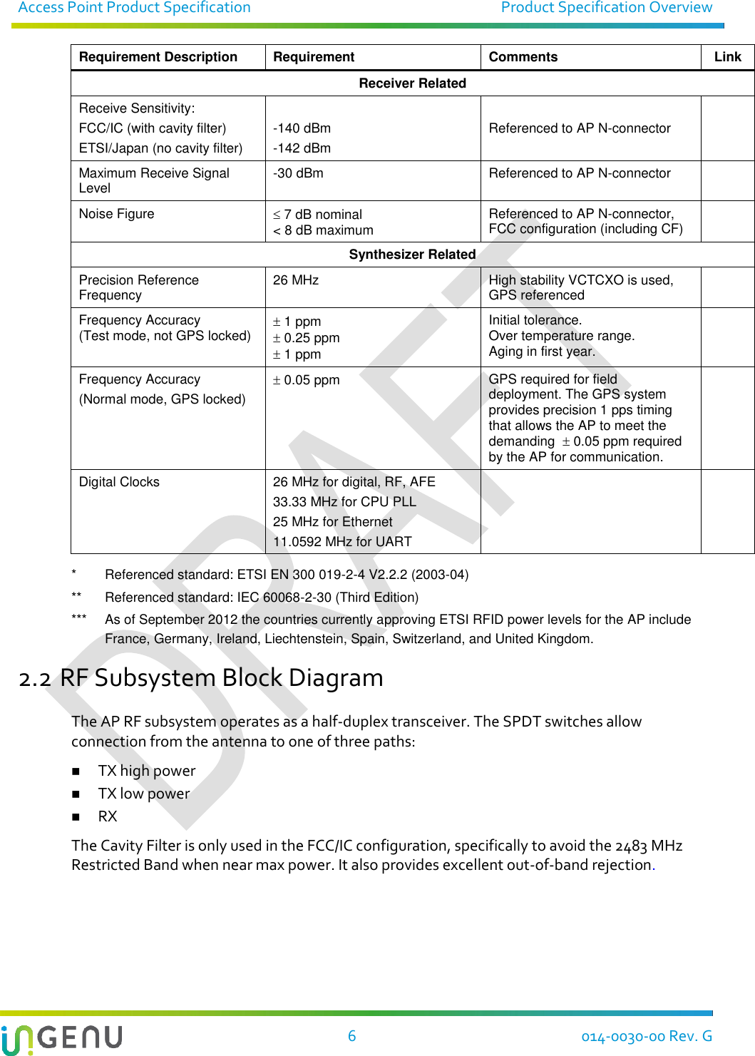
Ingenu ULPAP310 2.4GHz Spread Spectrum Device User Manual Access Point Product Specification
On-Ramp Wireless 2.4GHz Spread Spectrum Device Access Point Product Specification
Ingenu >
Contents
- 1. User Manual I
- 2. User Manual II
User Manual II

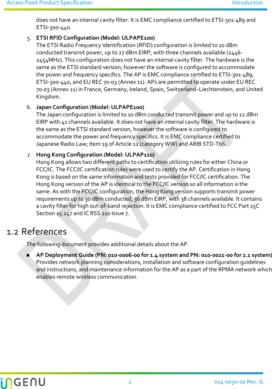
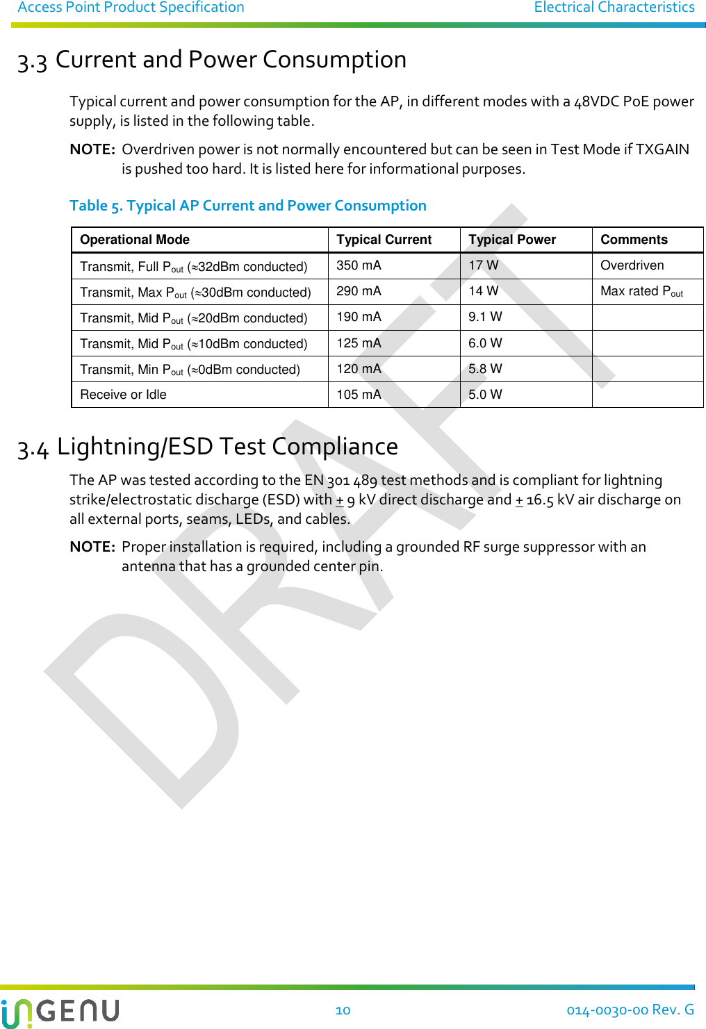
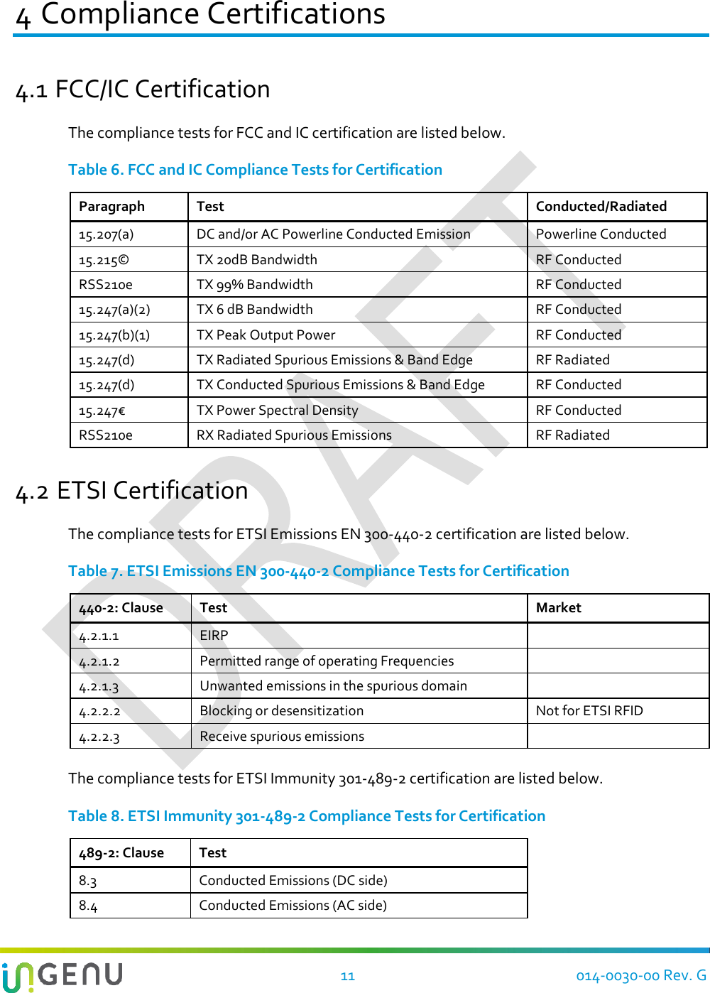
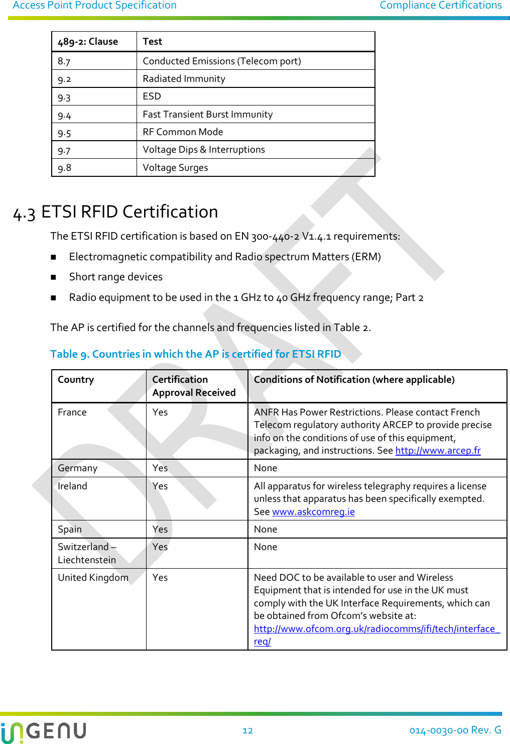
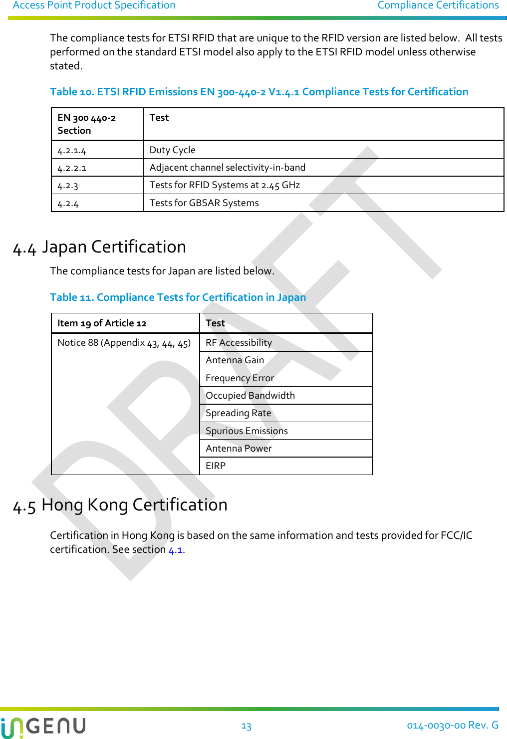
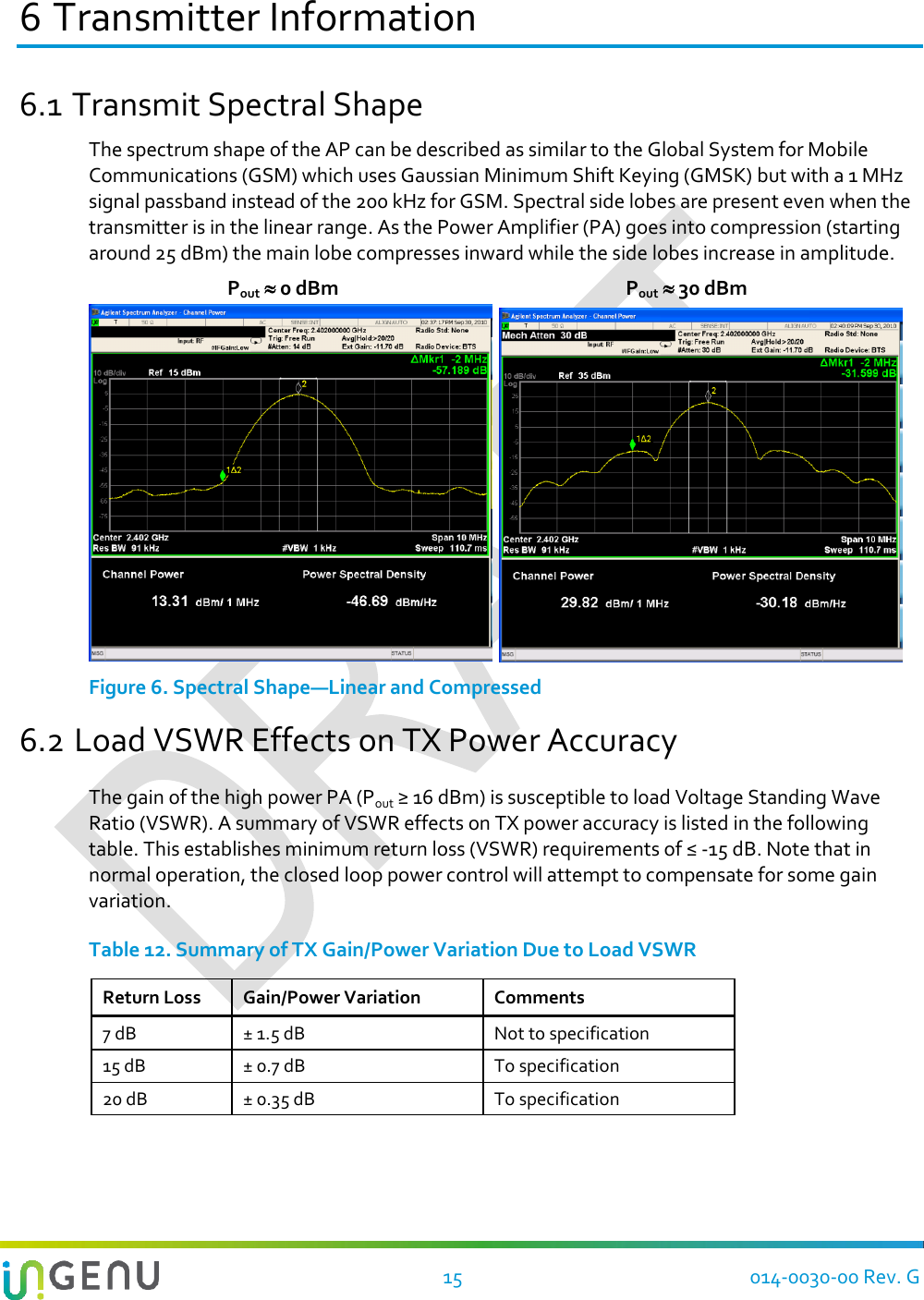
![9 014-0030-00 Rev. G 3 Electrical Characteristics 3.1 Power over Ethernet (PoE) The nominal 48VDC on the Ethernet cable is separated from the data and regulated with a switching power supply to 5.0VDC. This printed circuit board is equipped with lightning protection, surge protection, and differential and common mode filtering. It also includes a tamper protection device that will report to the system if the box cover has been opened. NOTE: The AP is not 802.3AF or 802.3AT compliant. It requires a dedicated passive injector and cannot be powered directly from most PoE switches. Table 3. Electrical Protection Surge Life (@500A 10/1000μs) Nominal Impulse Discharge Current (8/20μs) Nominal AC Discharge Current (10x1sec @50-60Hz) Max Impulse Discharge Current (1 Application @ 10/350μs) 400 shots 10 shots @ 20 kA 20 A 2.5 kA 3.2 Channel Numbering Channel numbers start at 2402 MHz and are spaced at 1.99 MHz intervals. The following table lists all channels. Note the following: ETSI also uses channels 39 and 40 (1-40). These are not available for the FCC/IC markets. Japan also has CH41 (2481.60 MHz, 1-41). These are not available for the FCC/IC markets. ETSI RFID only uses channels 24, 25, 26. Table 4. Channel Numbers vs. Frequency 1 [L] 2 3 4 5 6 7 8 9 10 2402.00 2403.99 2405.98 2407.97 2409.96 2411.95 2413.94 2415.93 2417.92 2419.91 11 12 13 14 15 16 17 18 19 20 [M] 2421.90 2423.89 2425.88 2427.87 2429.86 2431.85 2433.84 2435.83 2437.82 2439.81 21 22 23 24 25 26 27 28 29 30 2441.80 2443.79 2445.78 2447.77 2449.76 2451.75 2453.74 2455.73 2457.72 2459.71 31 32 33 34 35 36 37 38 [H] 39 40 2461.70 2463.69 2465.68 2467.67 2469.66 2471.65 2473.64 2475.63 2477.62 2479.61](https://usermanual.wiki/Ingenu/ULPAP310.User-Manual-II/User-Guide-2890431-Page-14.png)