Identiv PAT11211000 Physical Access Terminal User Manual PAT1121 Installation Manual
Identiv, Inc Physical Access Terminal PAT1121 Installation Manual
UserManual.wiki
>
Identiv
>
PAT11211000 User Manual
>
Users Manual 1121
Contents
1.
Users Manual 1111
2.
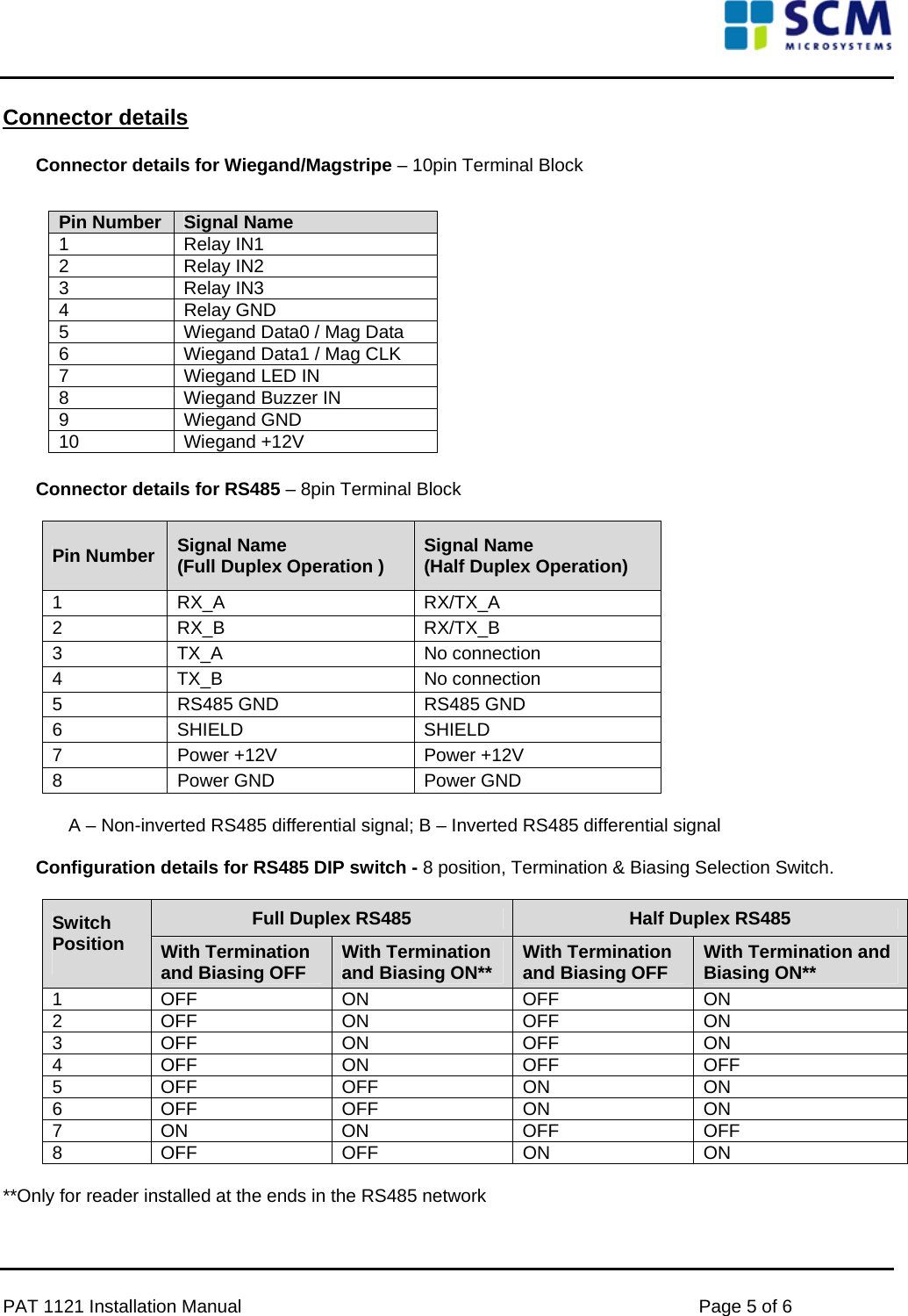
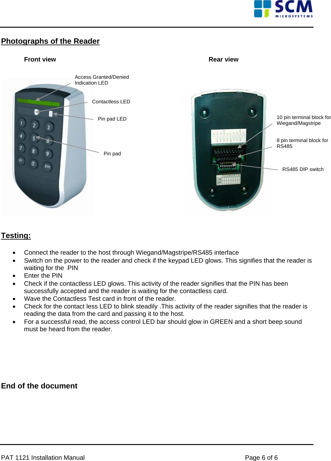
Users Manual 1121
Users Manual 1121
Navigation menu
Upload a User Manual
Namespaces
Wiki Guide
HTML
PDF
Info
Views
User Manual
Discussion / Help
Navigation