ISONAS orporated RC-01 PowerNet Proximity Reader-Controller User Manual
ISONAS Incorporated PowerNet Proximity Reader-Controller
UserManual.wiki
>
ISONAS orporated
>
RC 01 User Manual
User Manual
Navigation menu
Upload a User Manual
Namespaces
Wiki Guide
HTML
PDF
Info
Views
User Manual
Discussion / Help
Navigation

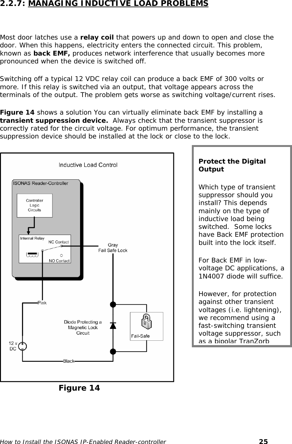
![1: BEFORE YOU BEGIN To install an ISONAS Reader-controller unit, you must complete three key wiring tasks: 1.Supply power to the Reader-controller unit. This may be accomplished with a power feed on the Ethernet Data cable (Power over Ethernet [PoE]) 1.Wire the unit to the door for physical access control. 1.Connect the unit to the data network for communication with the server/workstation PC. This guide discusses each wiring process separately. Understanding all of these processes makes this project much simpler and guarantees success. 1.1: GENERAL REQUIREMENTS: z If PoE is not being used, then use only UL-listed, access control, power-limited power supplies with an ‘AC on’ indicator light clearly visible on the enclosure. Power supplies should provide at least four hours of standby power. zNever connect power supplies to a switch-controlled receptacle. zInstall the ISONAS system in accordance with the National Electrical Code NFPA 70. (Local authority has jurisdiction.) zUse only suitable recognized wire or UL-listed cabling for ISONAS power supply and data communications, in accordance with the National Electrical Code. zWhere possible, separate ISONAS equipment and cabling from sources of electromagnetic interference (EMI). Where this is not possible, take other steps to reduce the effect of EMI on cabling or equipment. zProtect input and output terminals adequately from transient signals. Also, connect these terminals to power-limited circuitry. How to Install the ISONAS IP-Enabled Reader-controller 4](https://usermanual.wiki/ISONAS-orporated/RC-01/User-Guide-825313-Page-4.png)