IPICO Australia IP3911A LOW FREQUENCY SPORTS TIMING SYSTEM User Manual USERS MANUAL
IPICO Australia LOW FREQUENCY SPORTS TIMING SYSTEM USERS MANUAL
UserManual.wiki
>
IPICO Australia
>
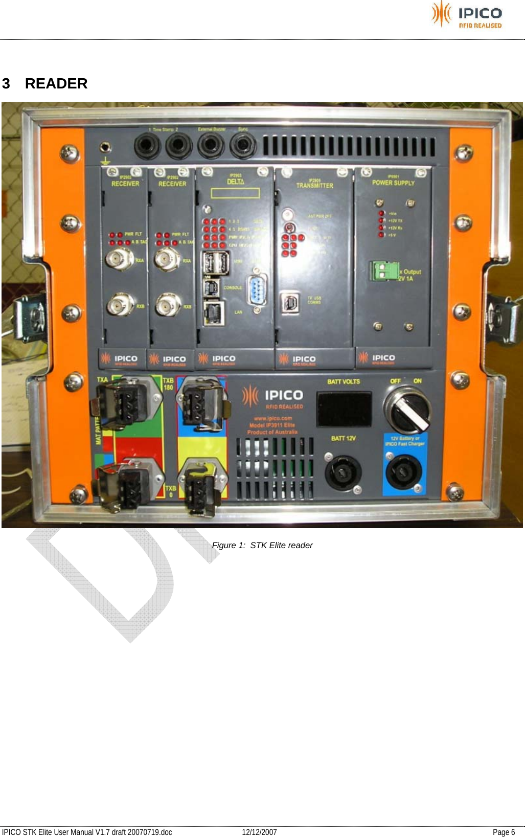
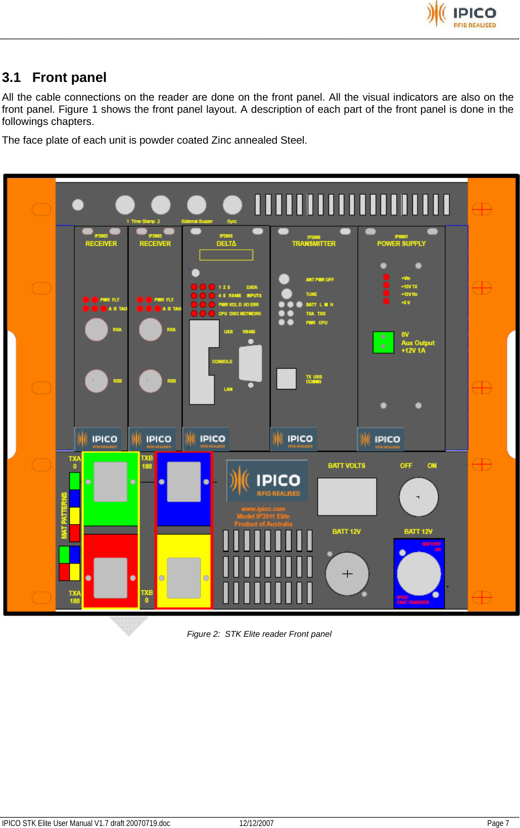
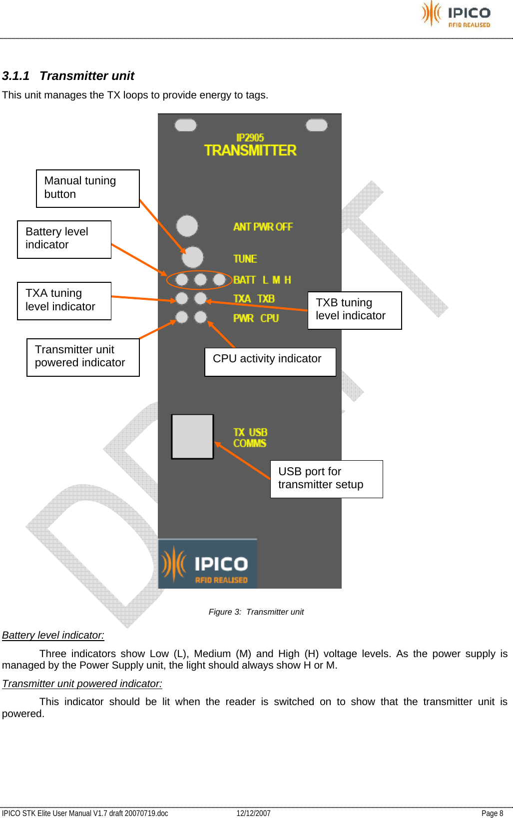
IP3911A User Manual
USERS MANUAL
Navigation menu
Upload a User Manual
Namespaces
Wiki Guide
HTML
PDF
Info
Views
User Manual
Discussion / Help
Navigation
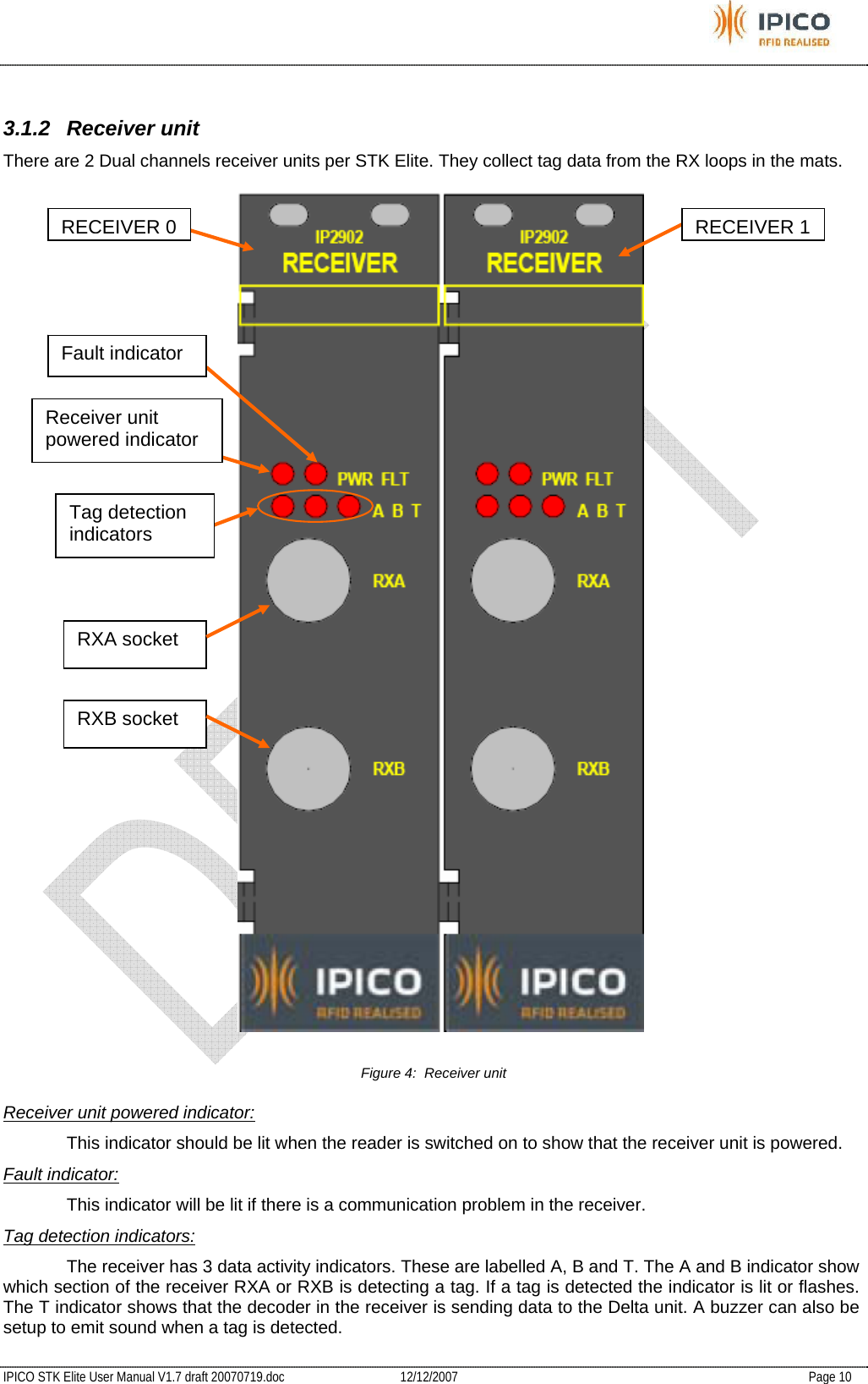
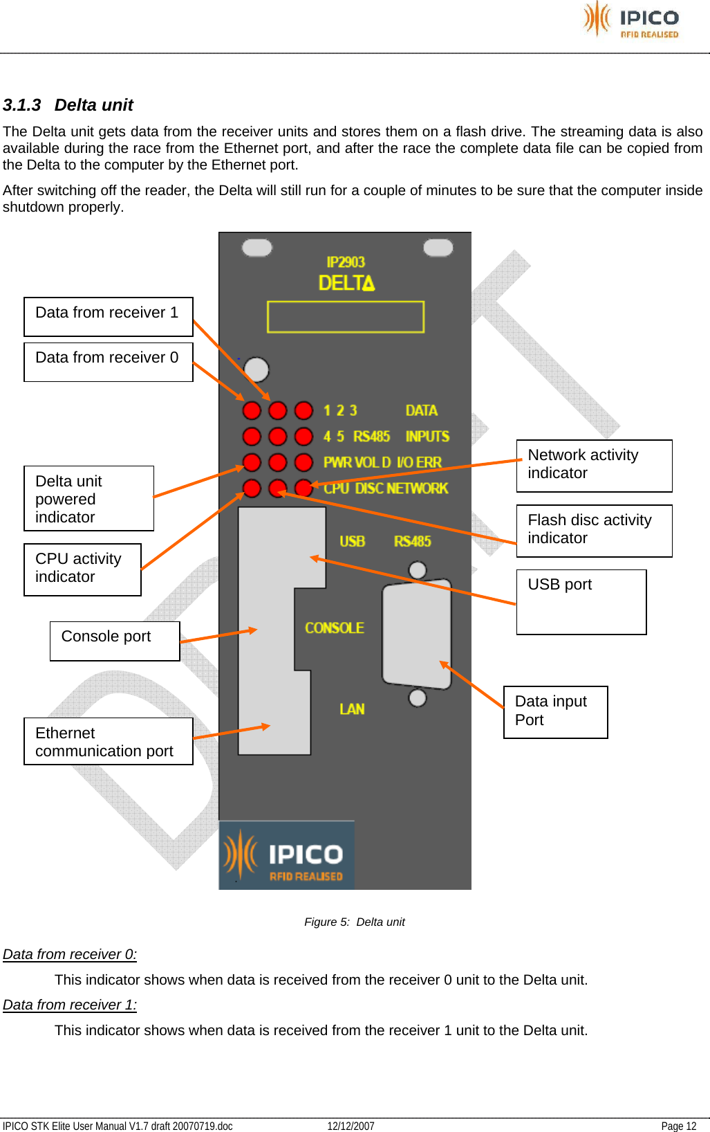
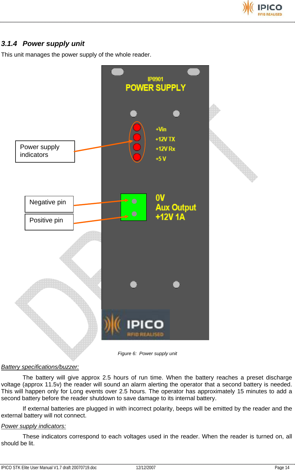
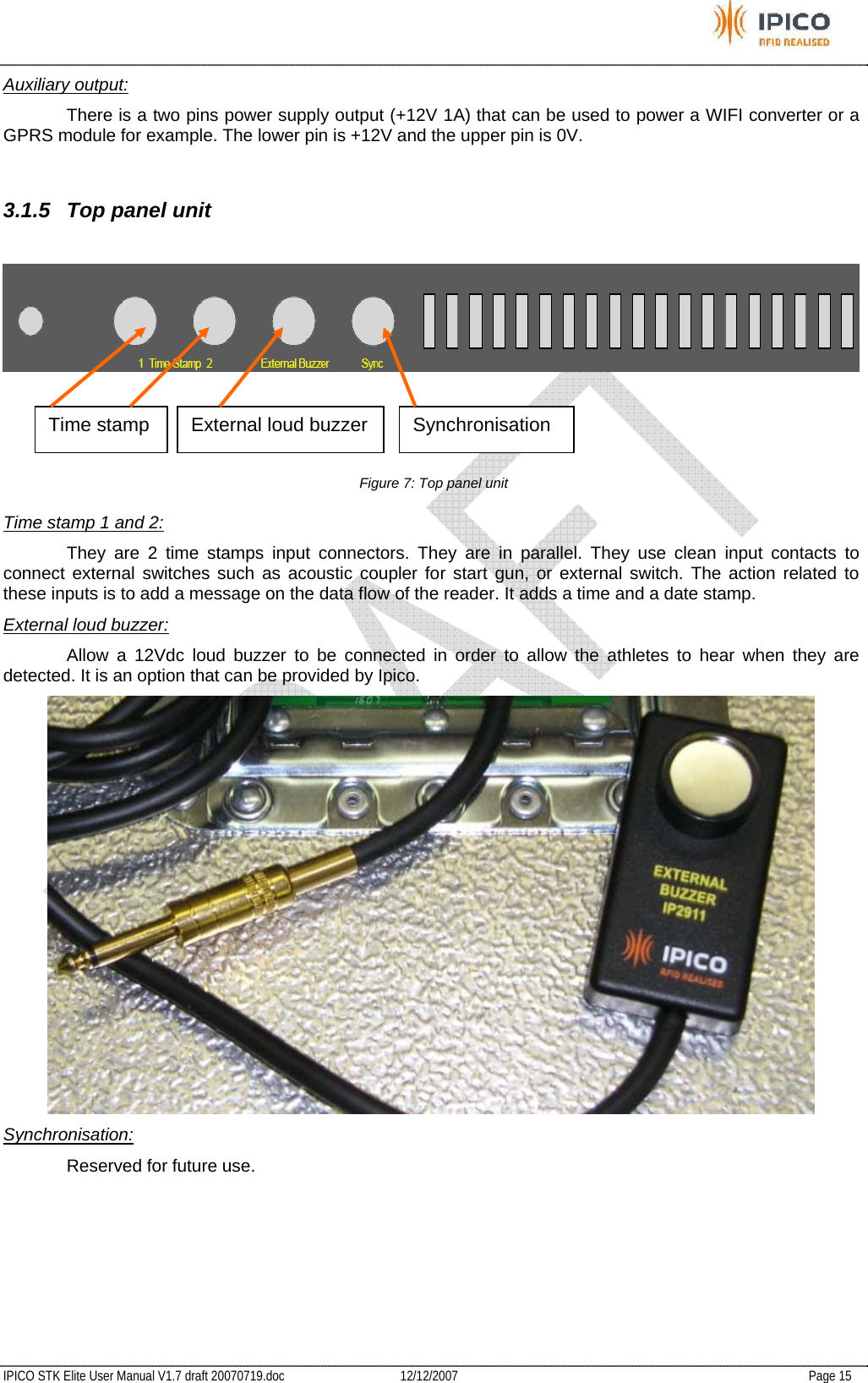
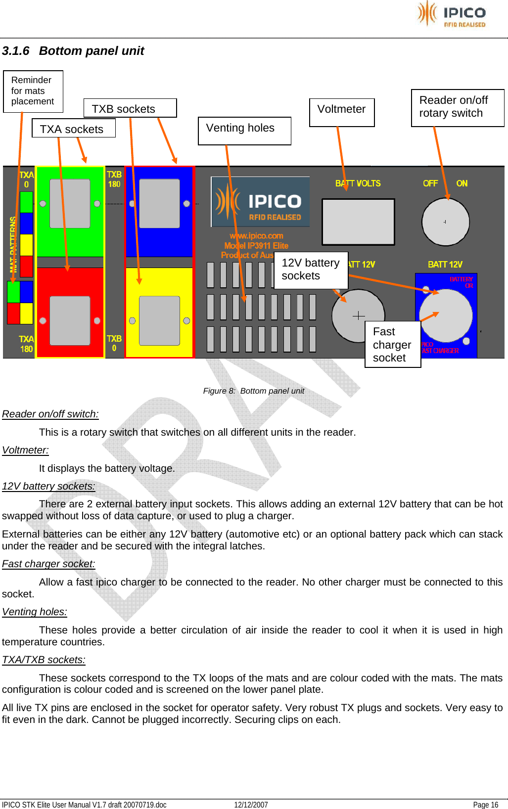
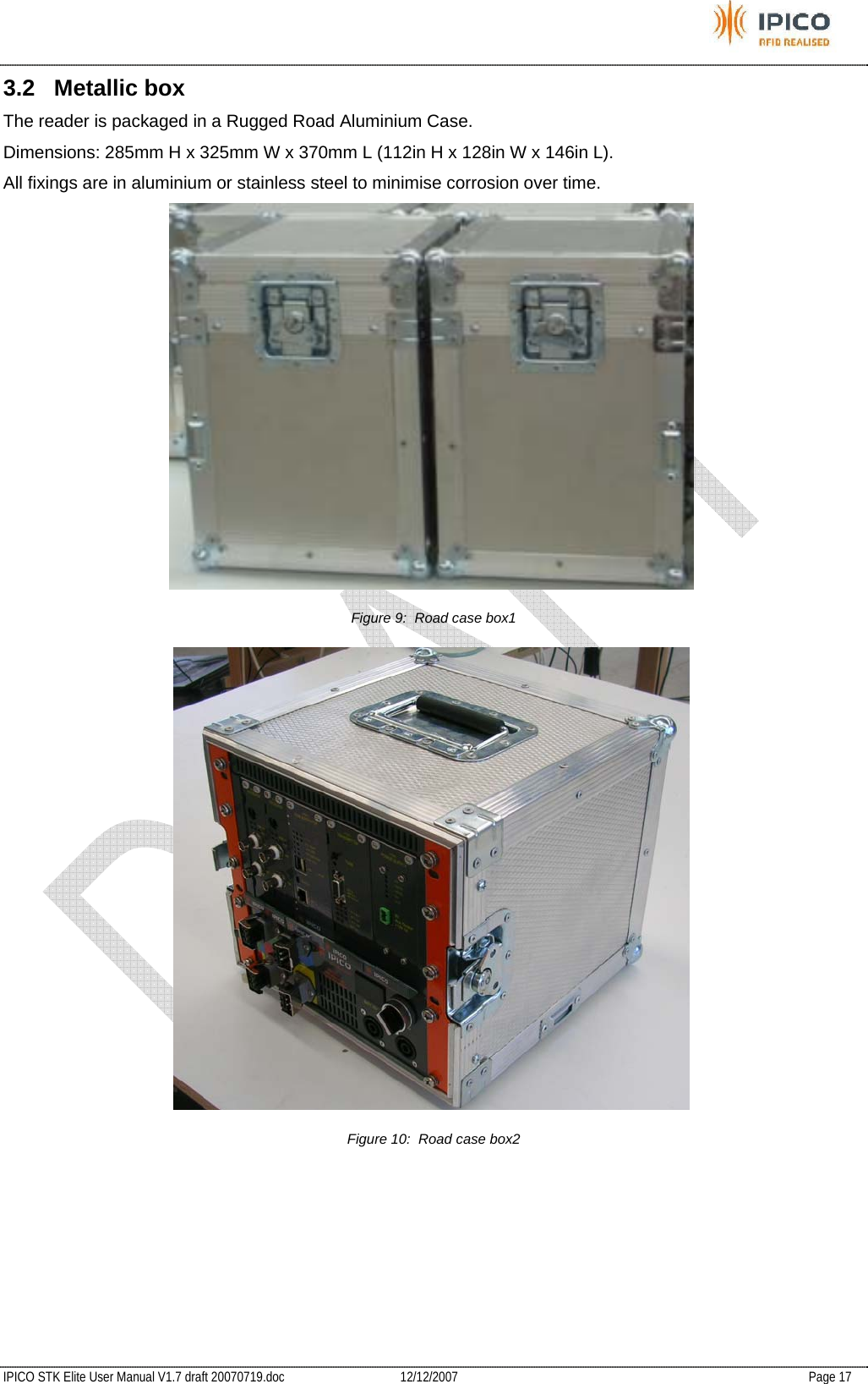
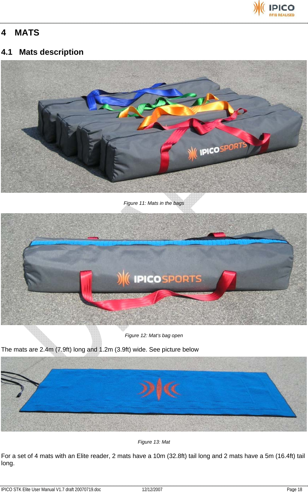
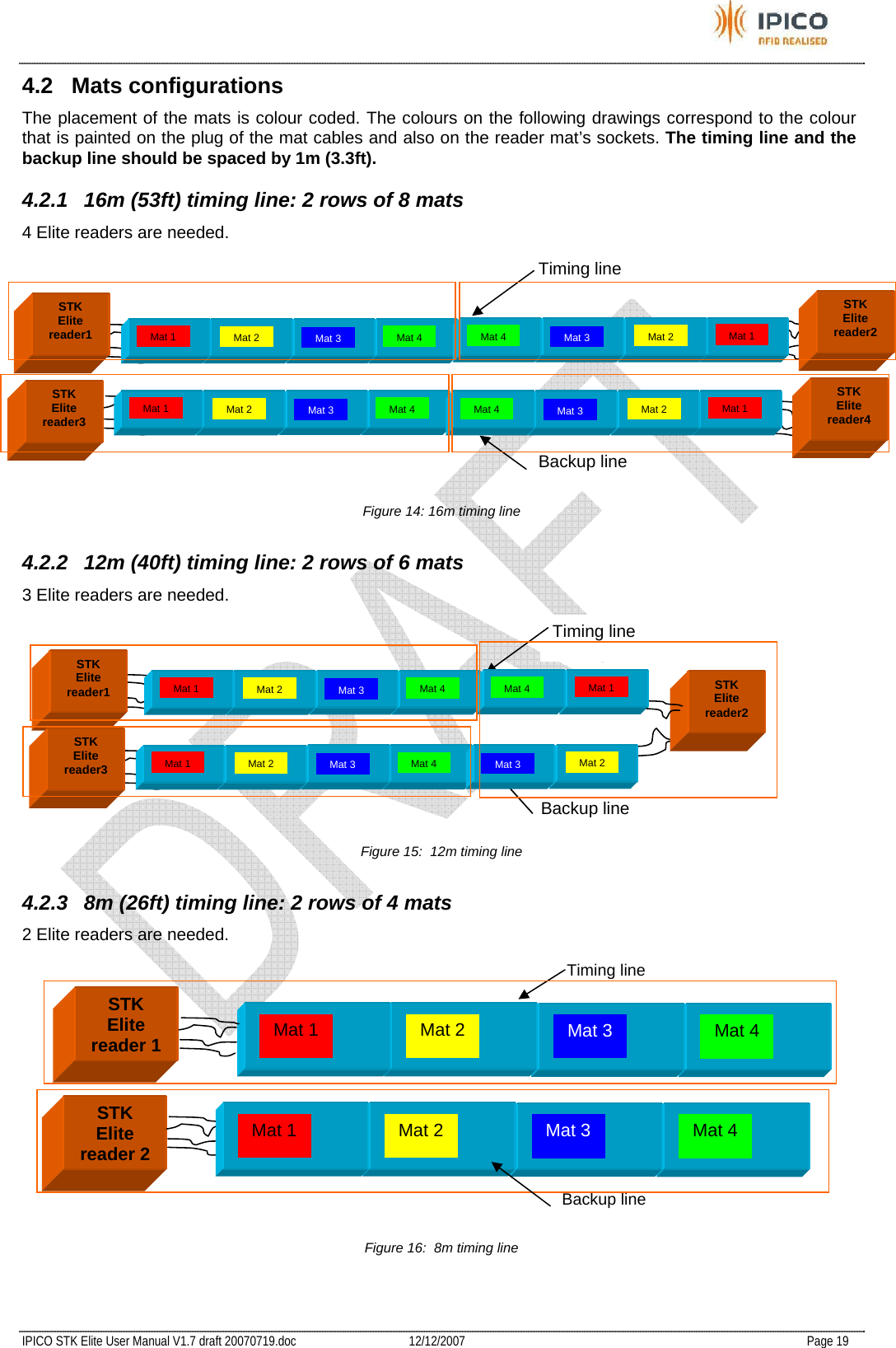
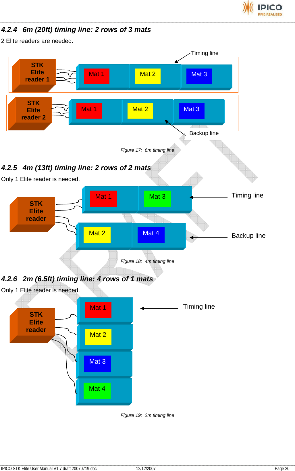
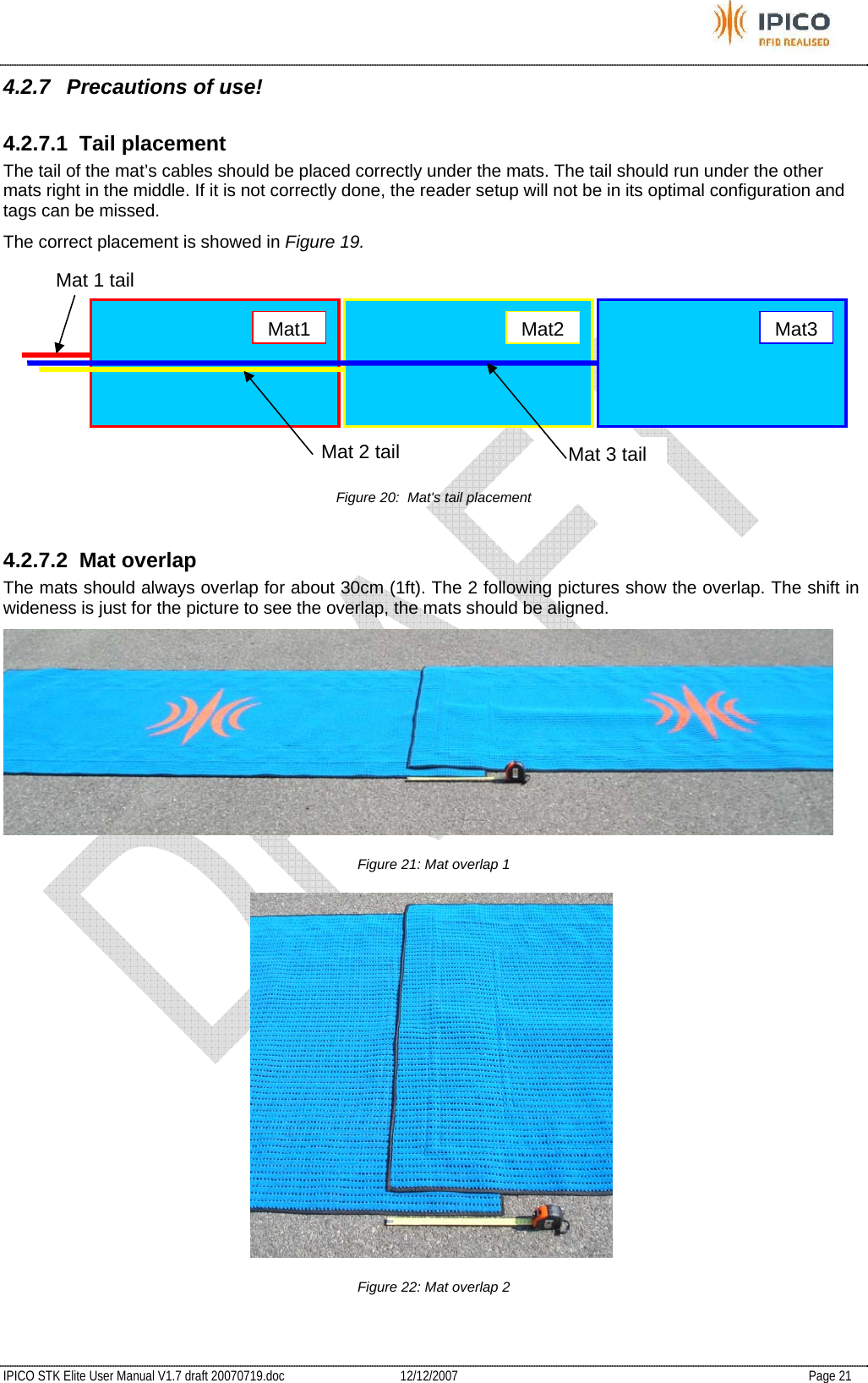
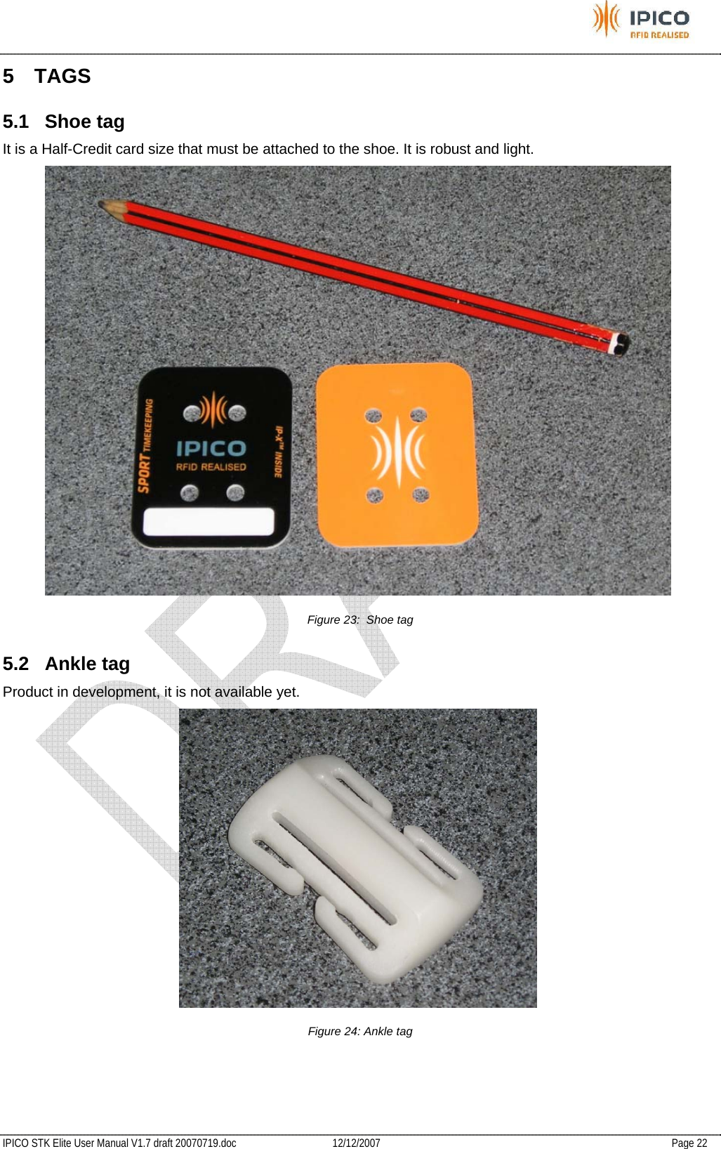
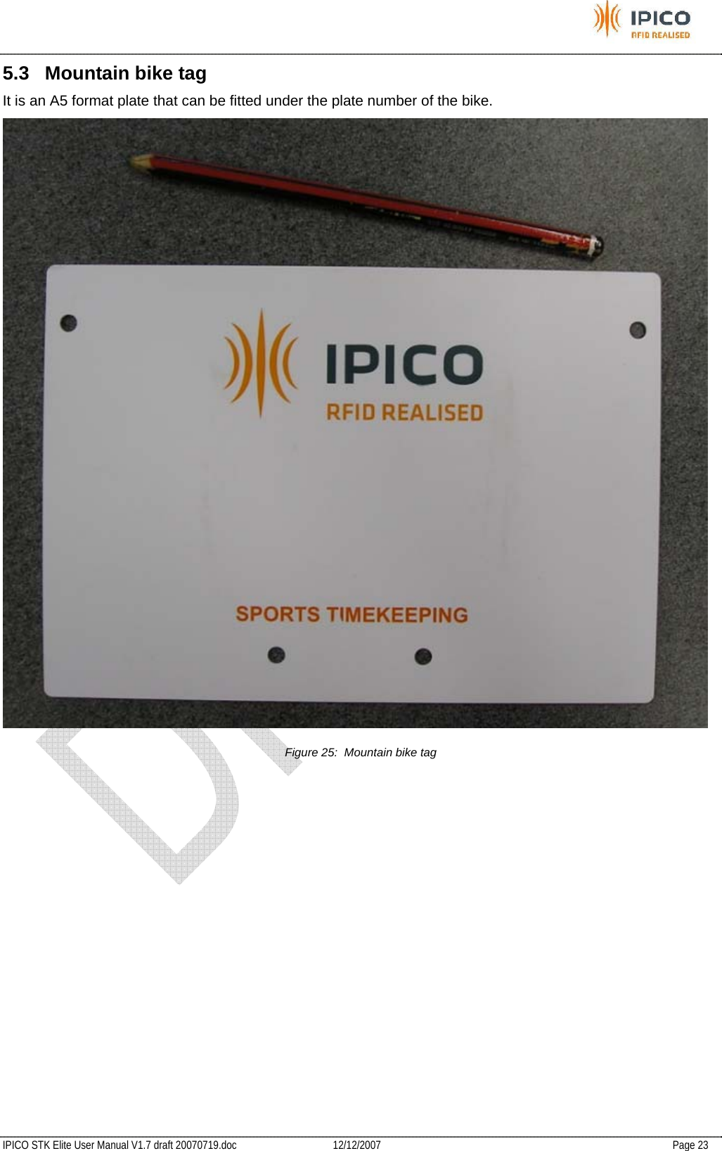
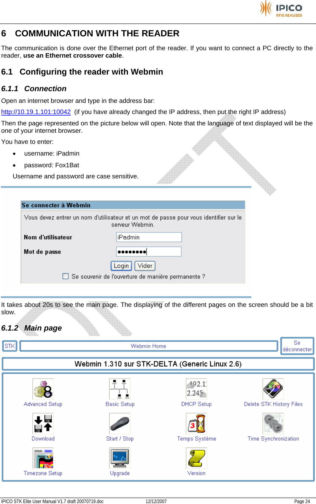
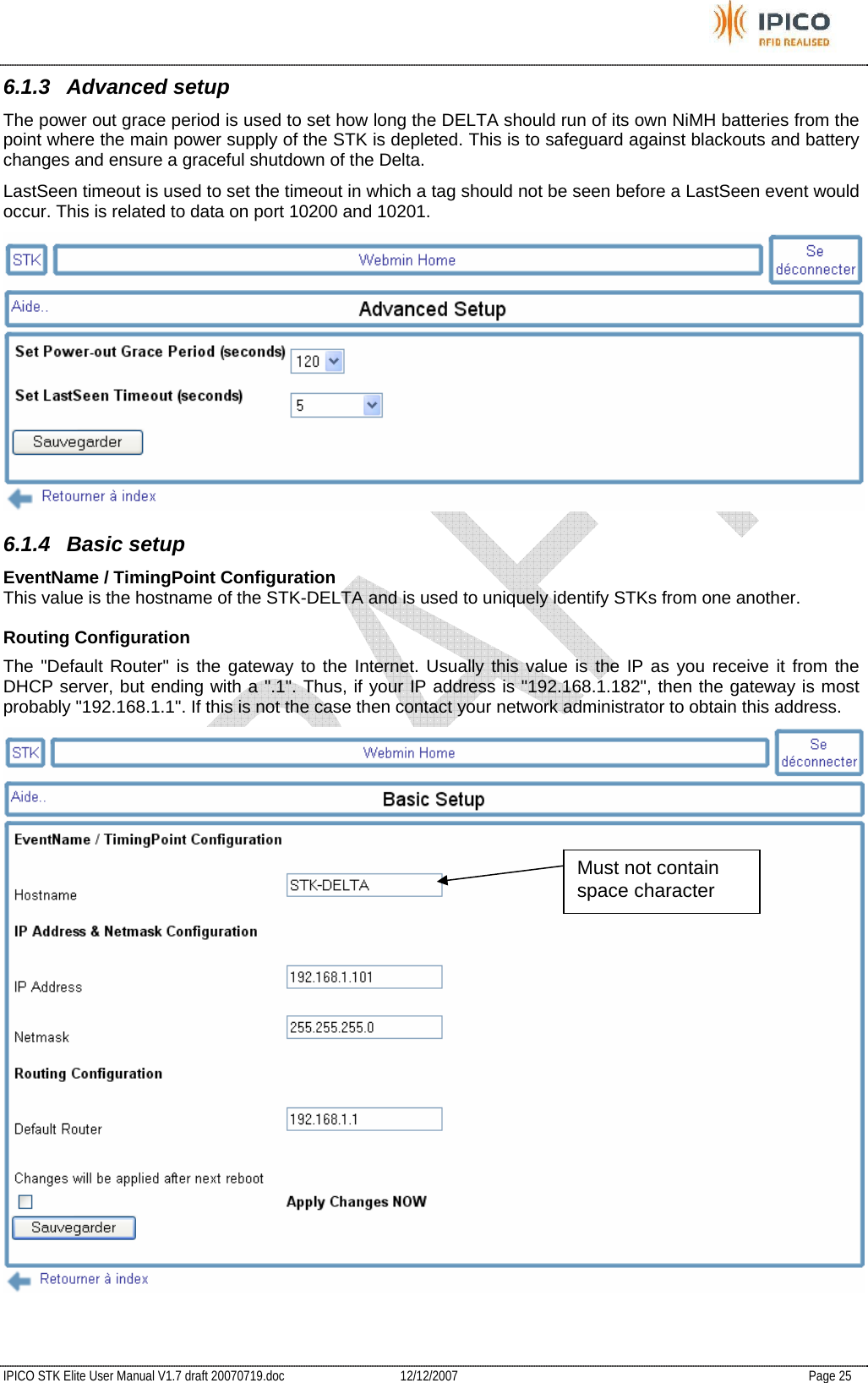
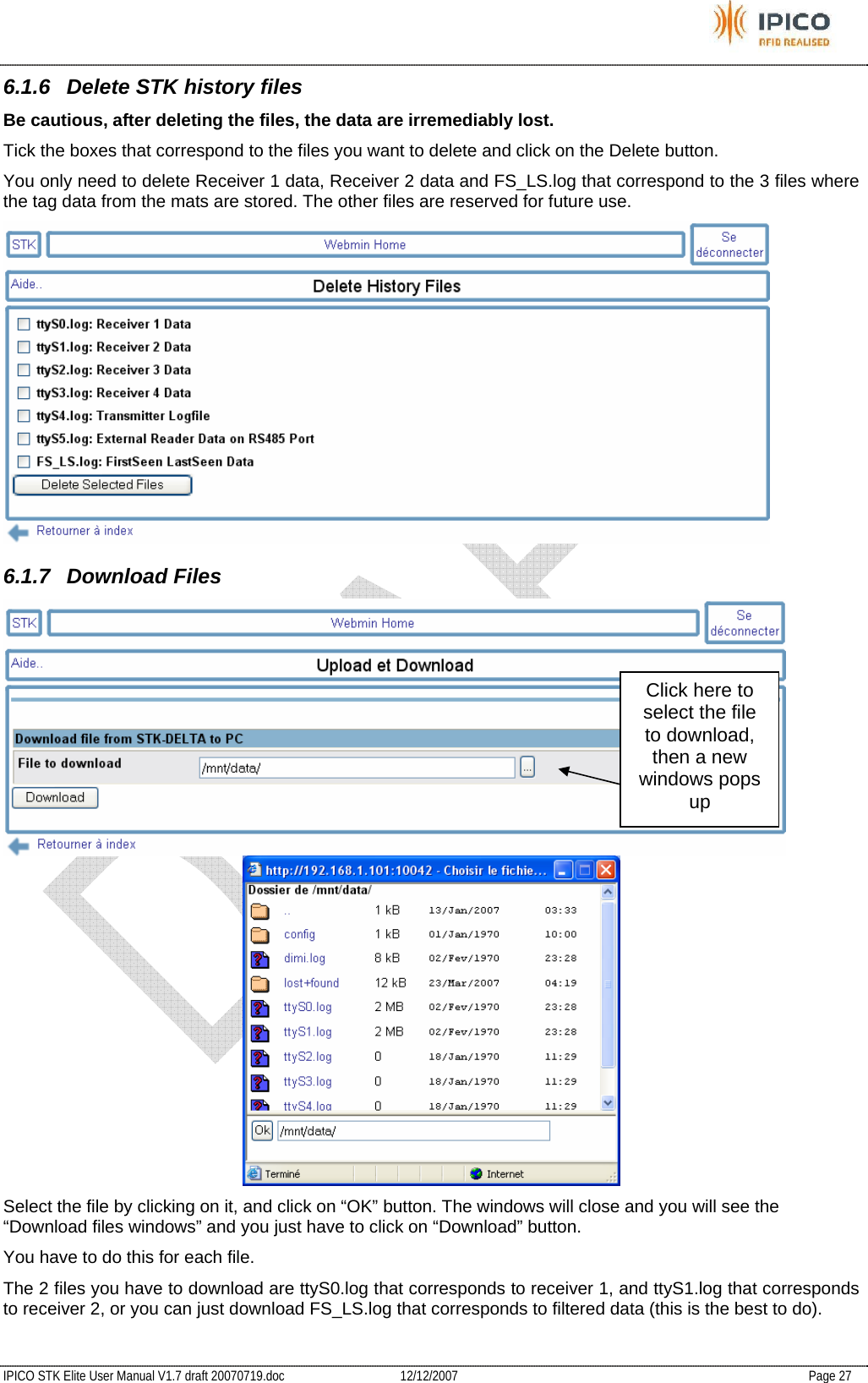
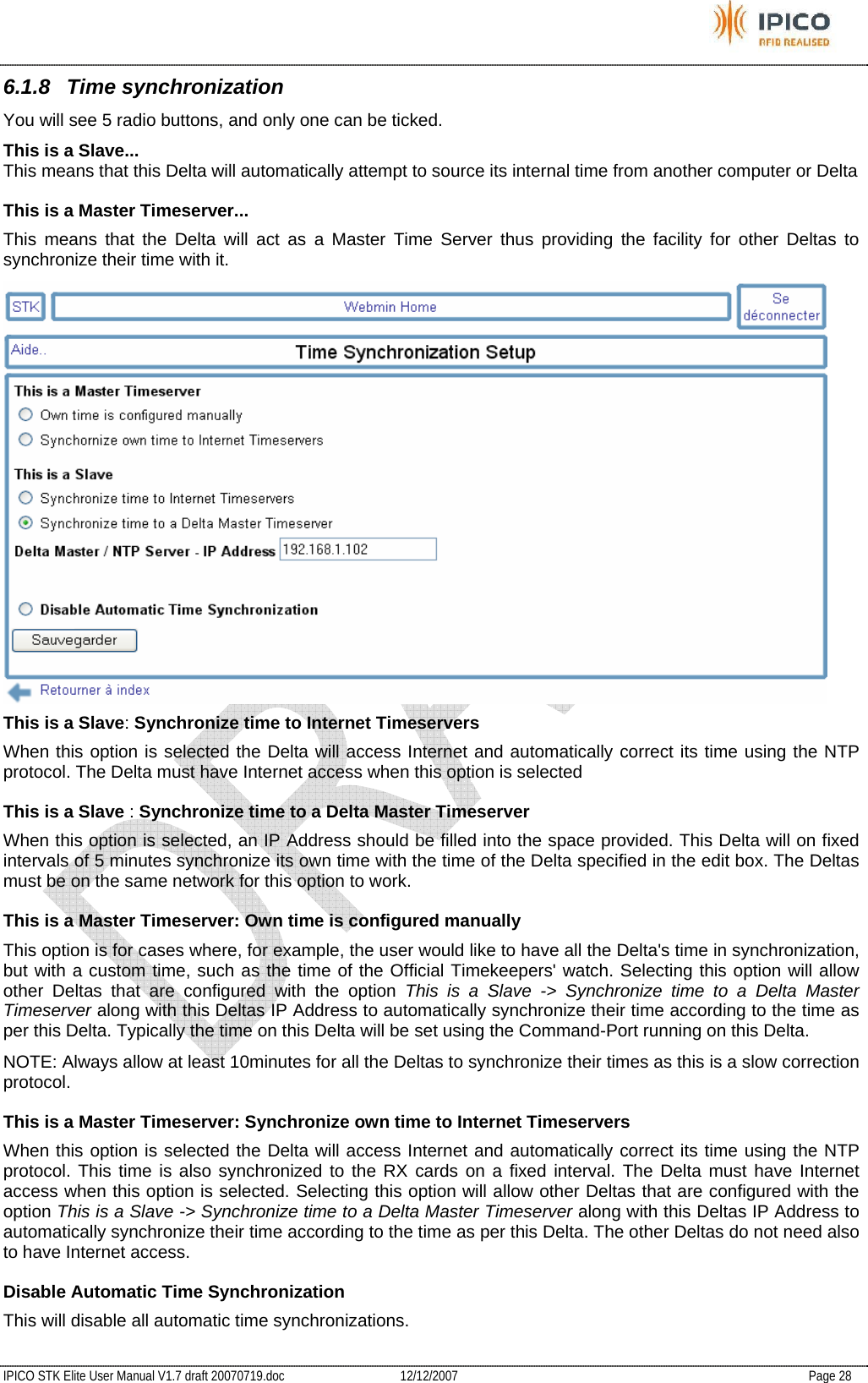
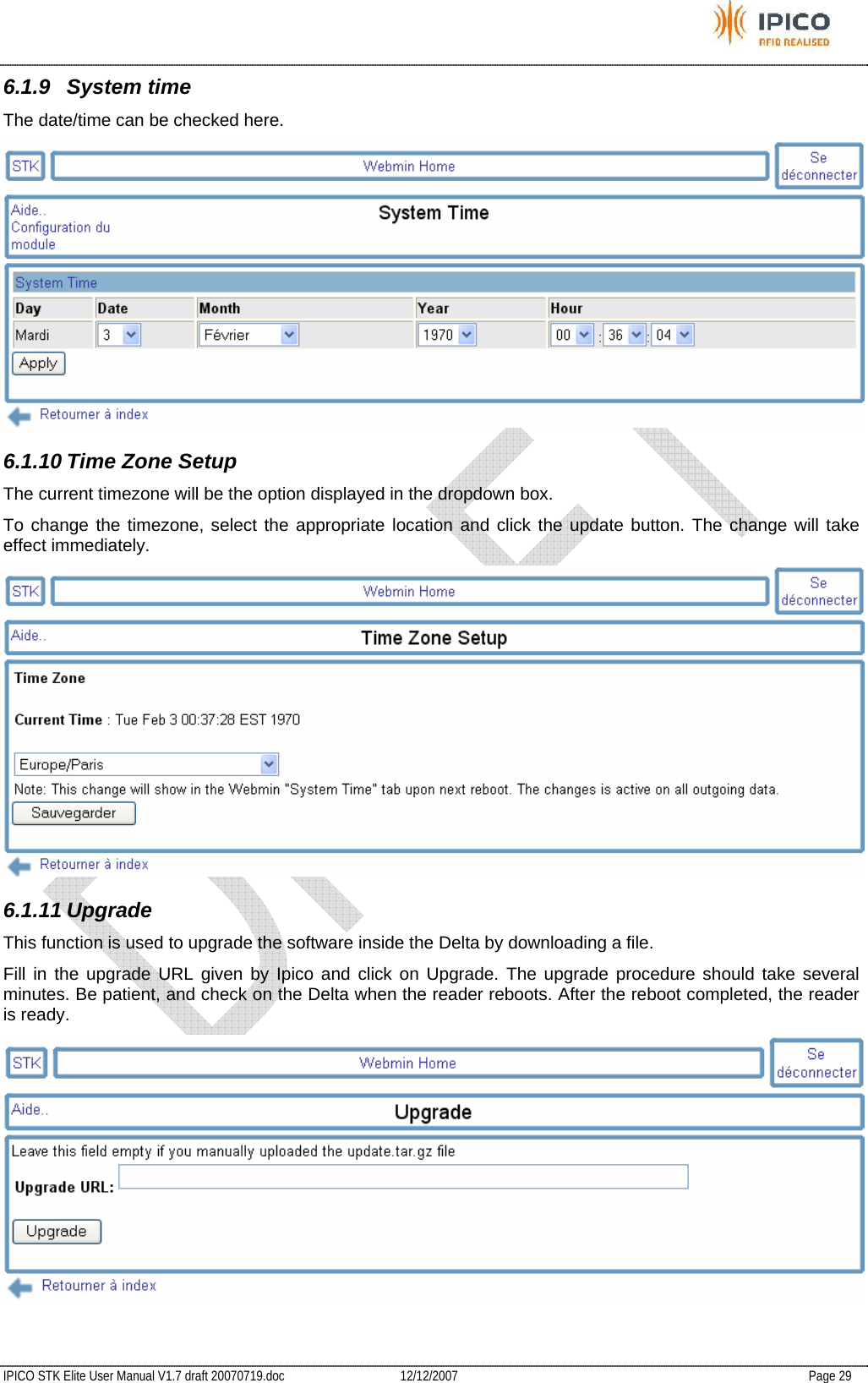
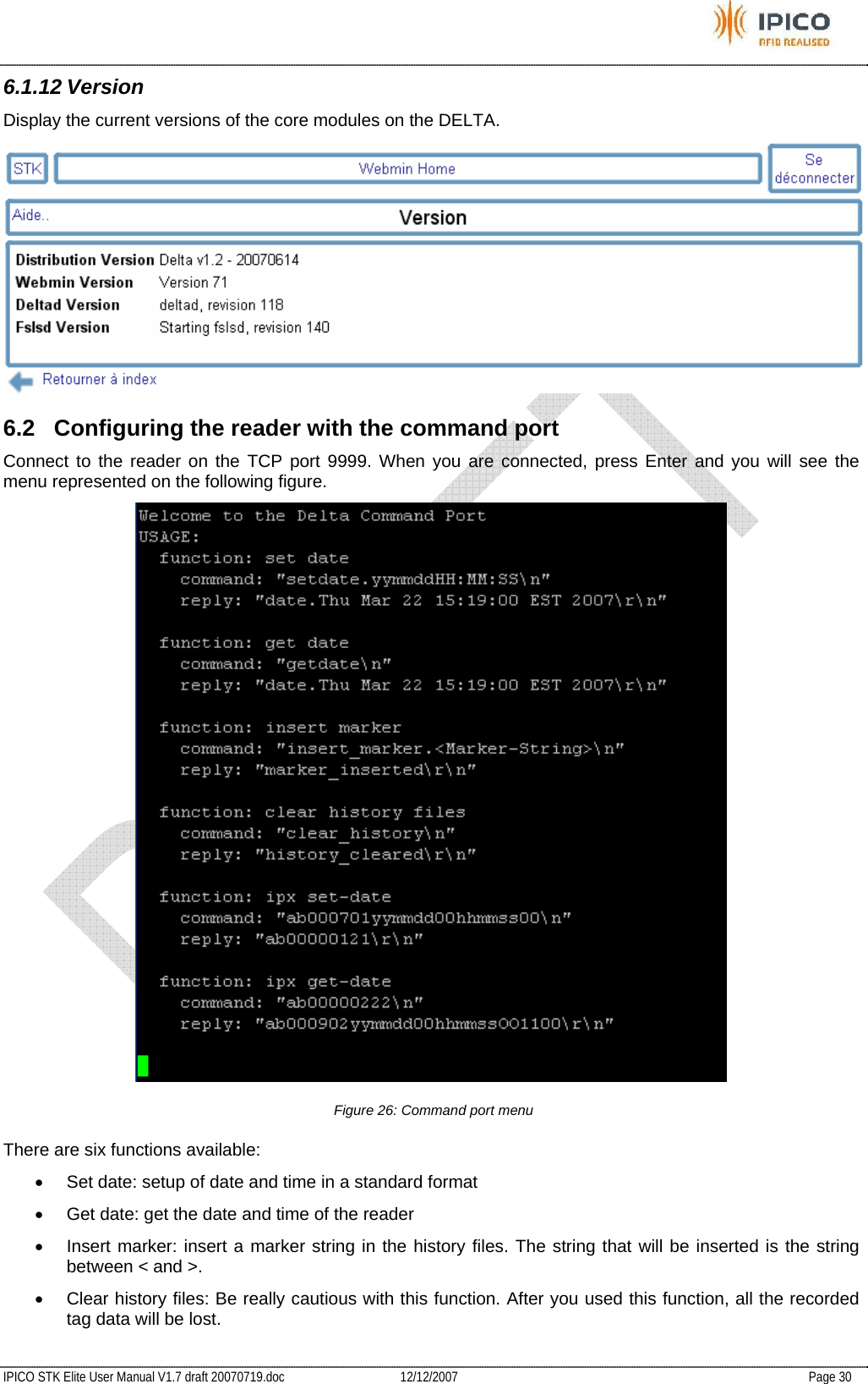
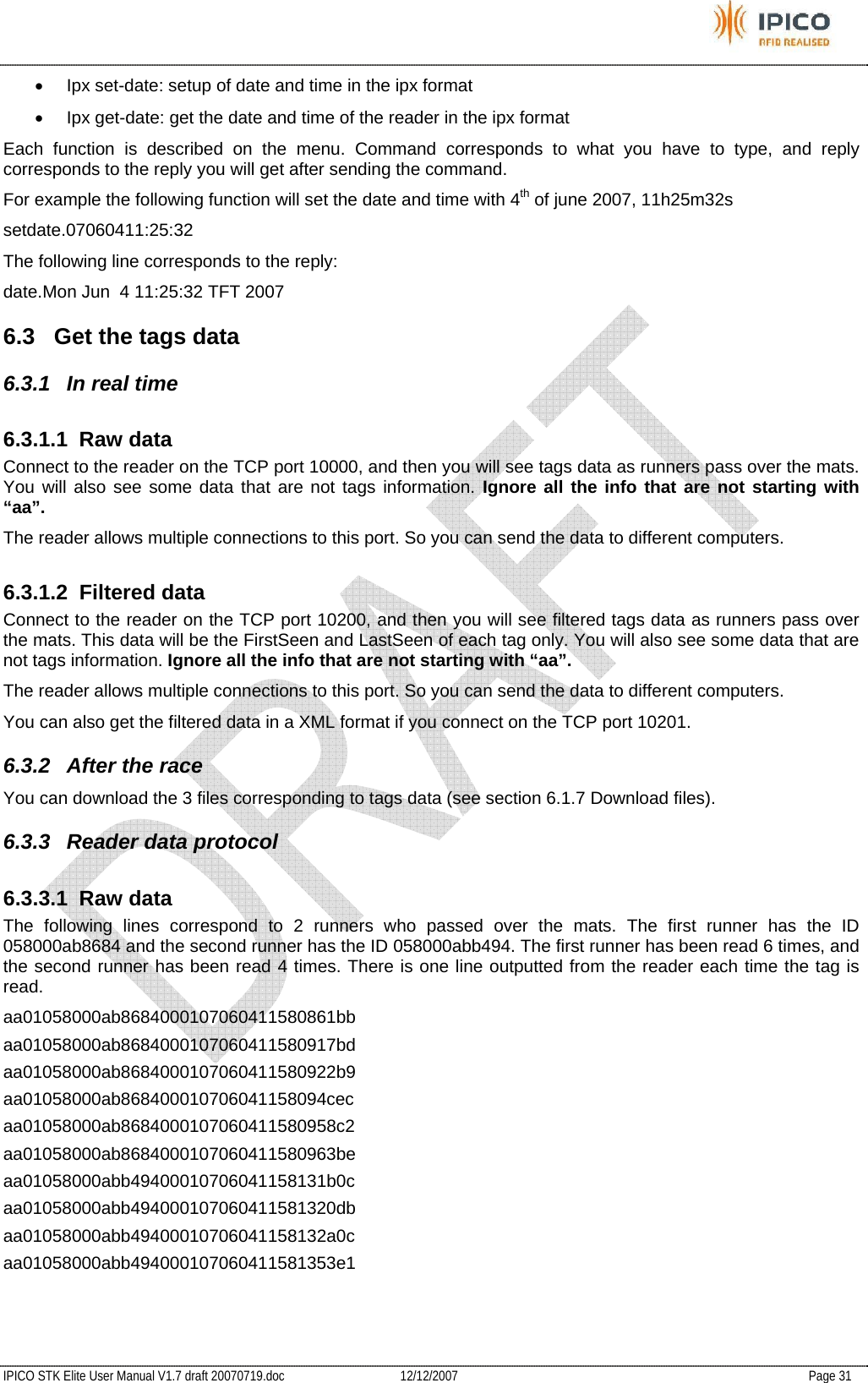
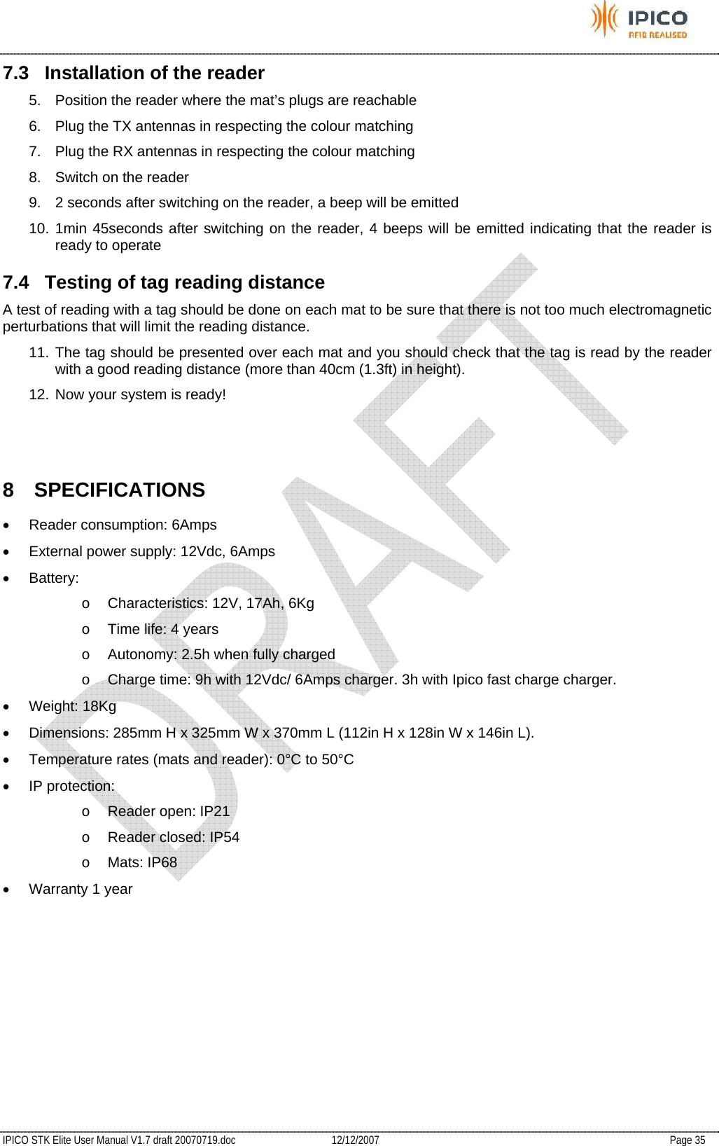
![IPICO STK Elite User Manual V1.7 draft 20070719.doc 12/12/2007 Page 26 IP Address & Netmask Configuration "IP Address" is the parameter that specifies the local IP address on the STK-DELTA. For you and other STKs to see each other on a network they all have to be on the same subnet. Thus, if your IP address is "192.168.1.182" then all the other STKs must also have an IP address starting with "192.168.1.*", where the "*" is replaced with a unique number for each device on the network. Apply Changes Now If you select this option the changes will be implemented immediately. This will require your connection to the STK-DELTA to be reset. Some browsers might re-establish this connection but it might be necessary to manually re-connect with the Browser Refresh option. 6.1.5 DHCP setup DHCP HOST When a STK-DELTA is a DHCP Host it means that the STK-DELTA will lease an IP address to any host on the same subnet requesting an IP via DHCP. When you want to prepare your STK-DELTA to access it via Ethernet while you will not be on a network somewhere, you have one of 2 choices: 1) Change the IP of your Notebook/PC to a static IP on the same subnet than the IP configured on the STK-DELTA. In this case the DHCP option of the STK-DELTA should be "DHCP Disabled" OR 2) Enable the DHCP option of the STK-DELTA to "DHCP Host". In this case you will not need to change the IP on you Notebook/PC and if you have DHCP enabled on your Notebook/PC, you will be ableto access the STK-DELTA on the configured IP of the STK-DELTA. NOTE 1: Only ONE DHCP server should be active on a network. Do not leave your STK-DELTA in DHCP-HOST mode while on your office/home network since it will interfere with your current DHCP HOST. NOTE 2: The STK-DELTA will lease IP addresses in the range that is 10 IPs away on either side of the local IP. This if your IP is 192.168.1.100, the leased DHCP IPs will be in the range 192.168.1.[1..90] and 192.168.1.[110..250]. Thus, if you have other statically defined addresses on the same subnet, then select them within the 20 IP range around the local IP to avoid clashes. DHCP Disabled In this option the STK-DELTA will not lease any IP addresses to requesting hosts and will still be available on the configured IP address. Apply Changes Now If you select this option the option you selected will be enforced immediately. This will necessarily entails that your connection to the STK-DELTA will be reset. Some browsers might re-establish this connection but it might be necessary to manually re-connect.](https://usermanual.wiki/IPICO-Australia/IP3911A/User-Guide-880724-Page-27.png)