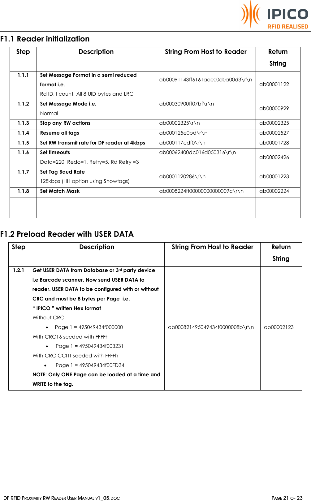
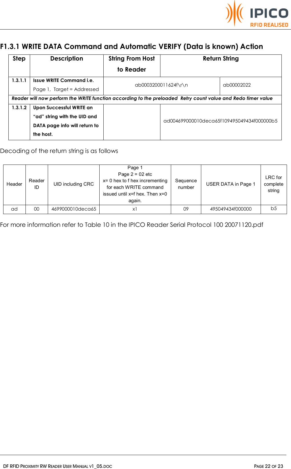
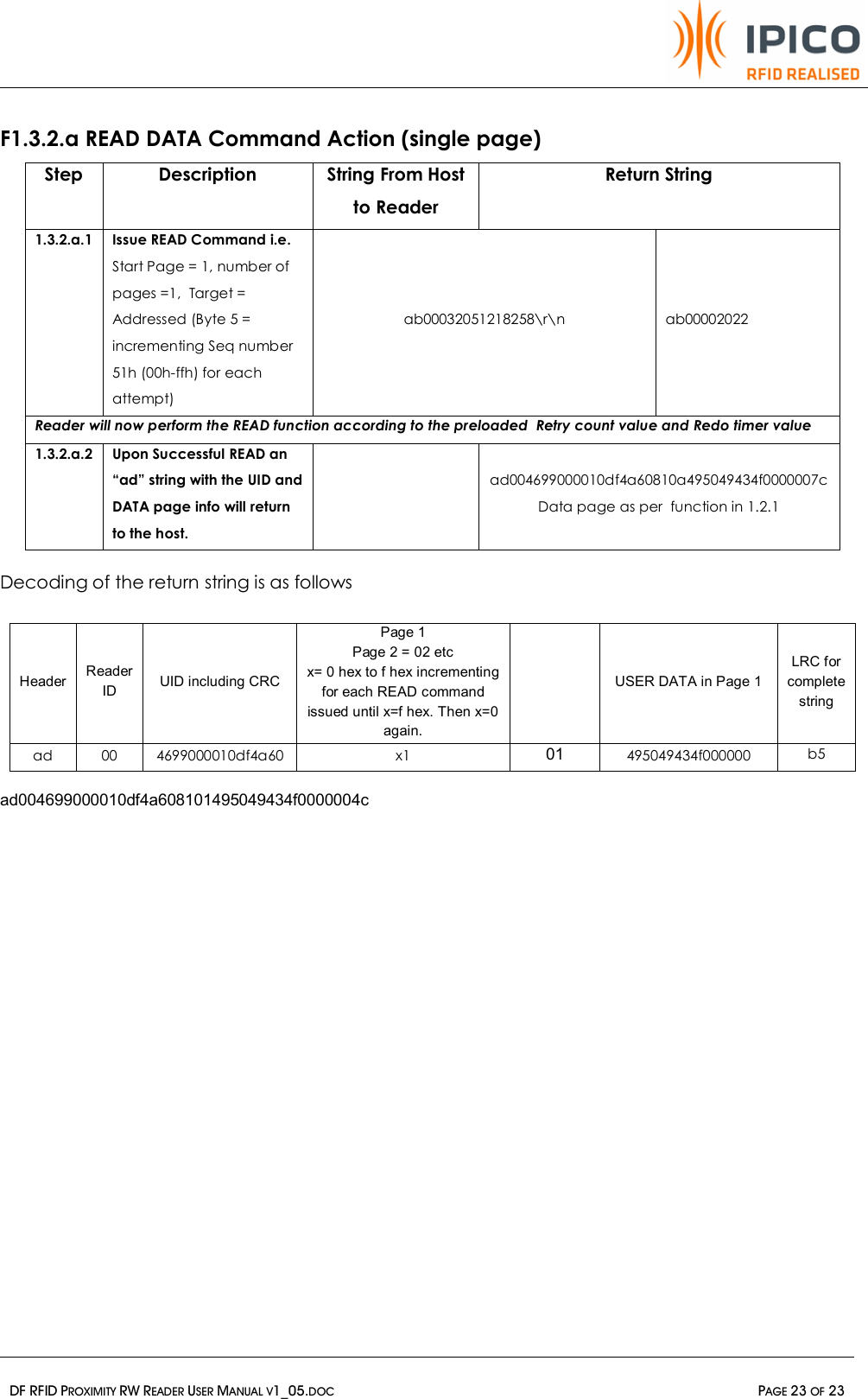
IPICO Australia IP3490A DUAL FREQUENCY PROXIMITY RFID READER User Manual DF RFID Proximity RW Reader v1 05
IPICO Australia DUAL FREQUENCY PROXIMITY RFID READER DF RFID Proximity RW Reader v1 05
UserManual.wiki
>
IPICO Australia
>
IP3490A User Manual
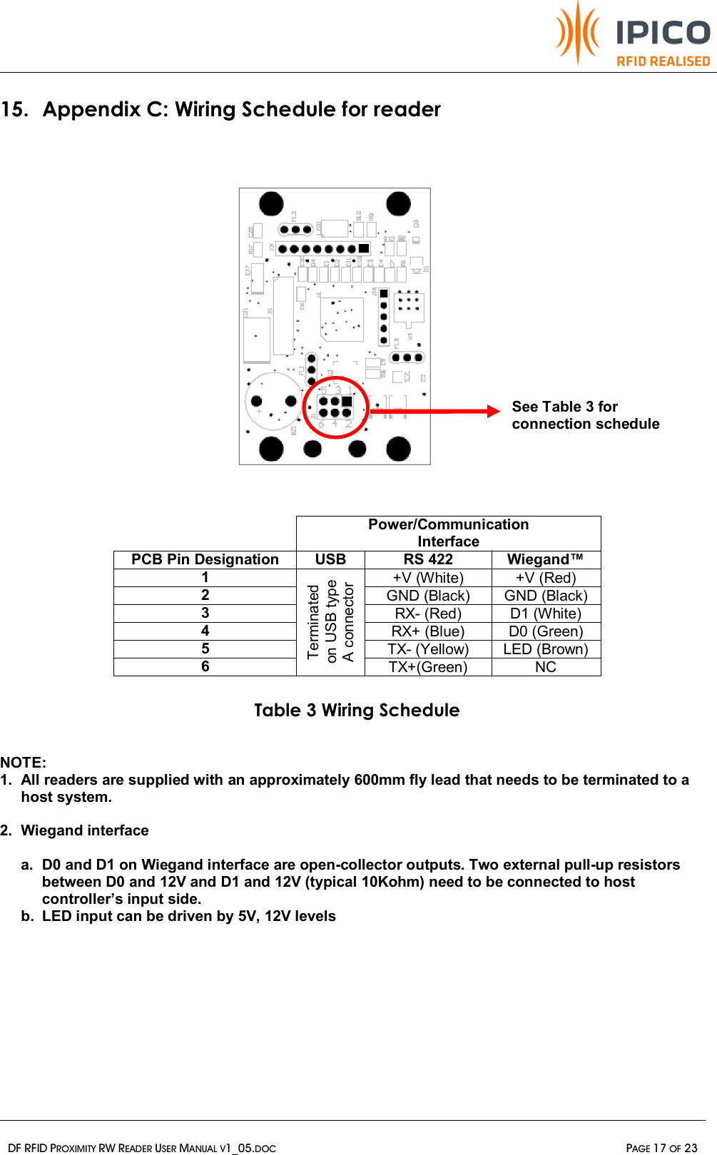
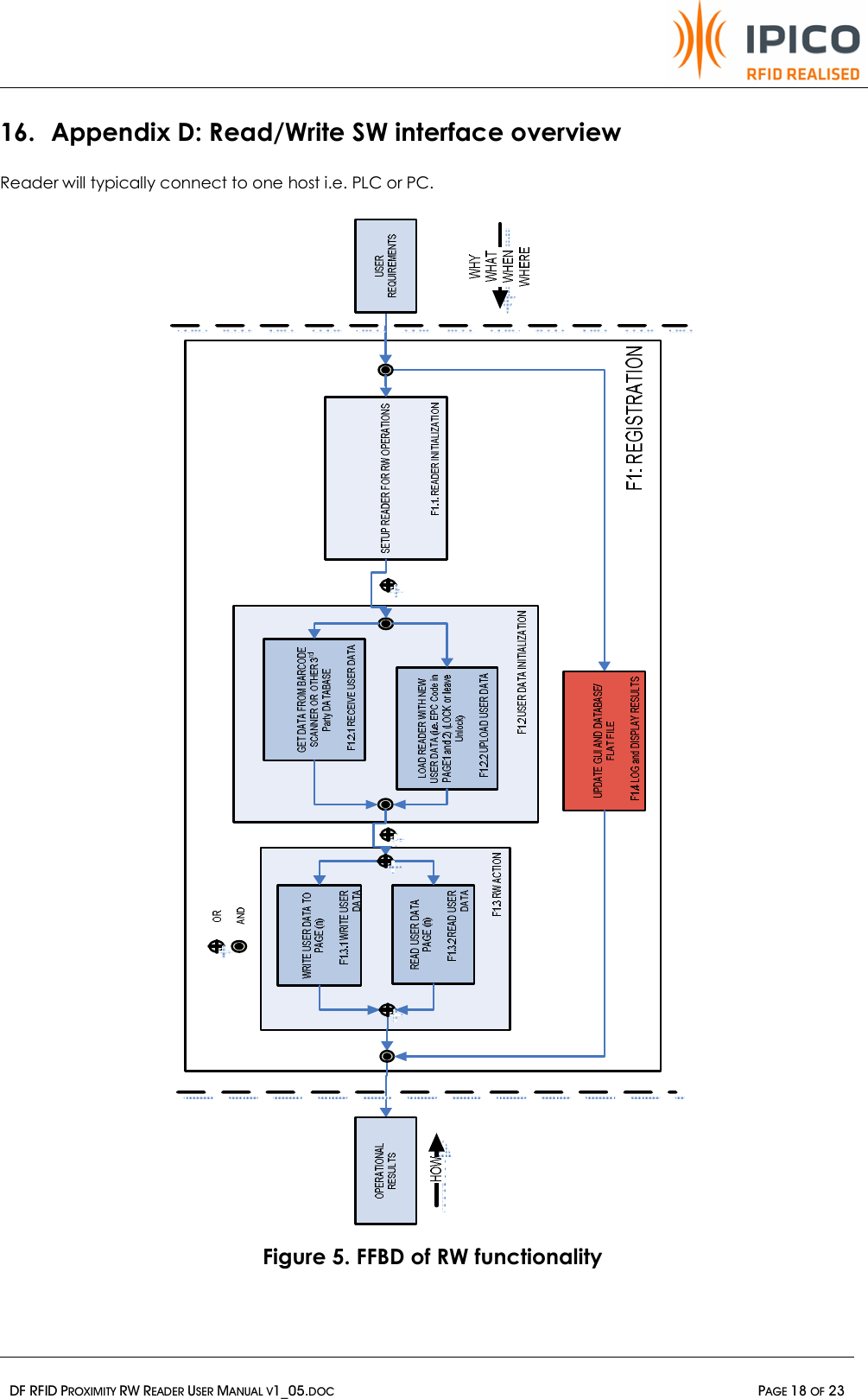
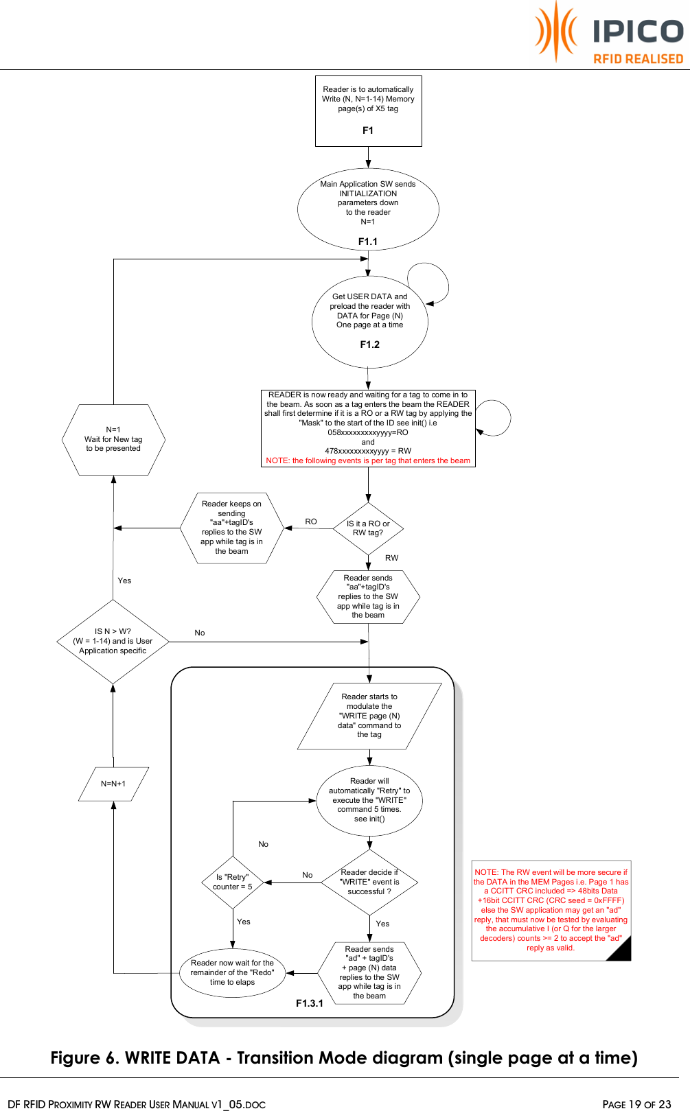
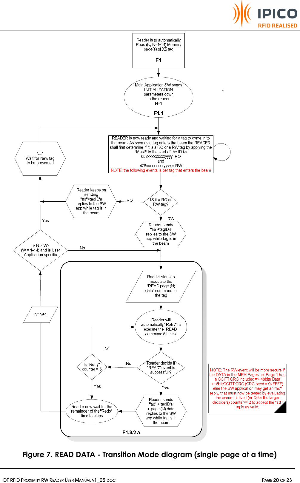
USERS MANUAL
Navigation menu
Upload a User Manual
Namespaces
Wiki Guide
HTML
PDF
Info
Views
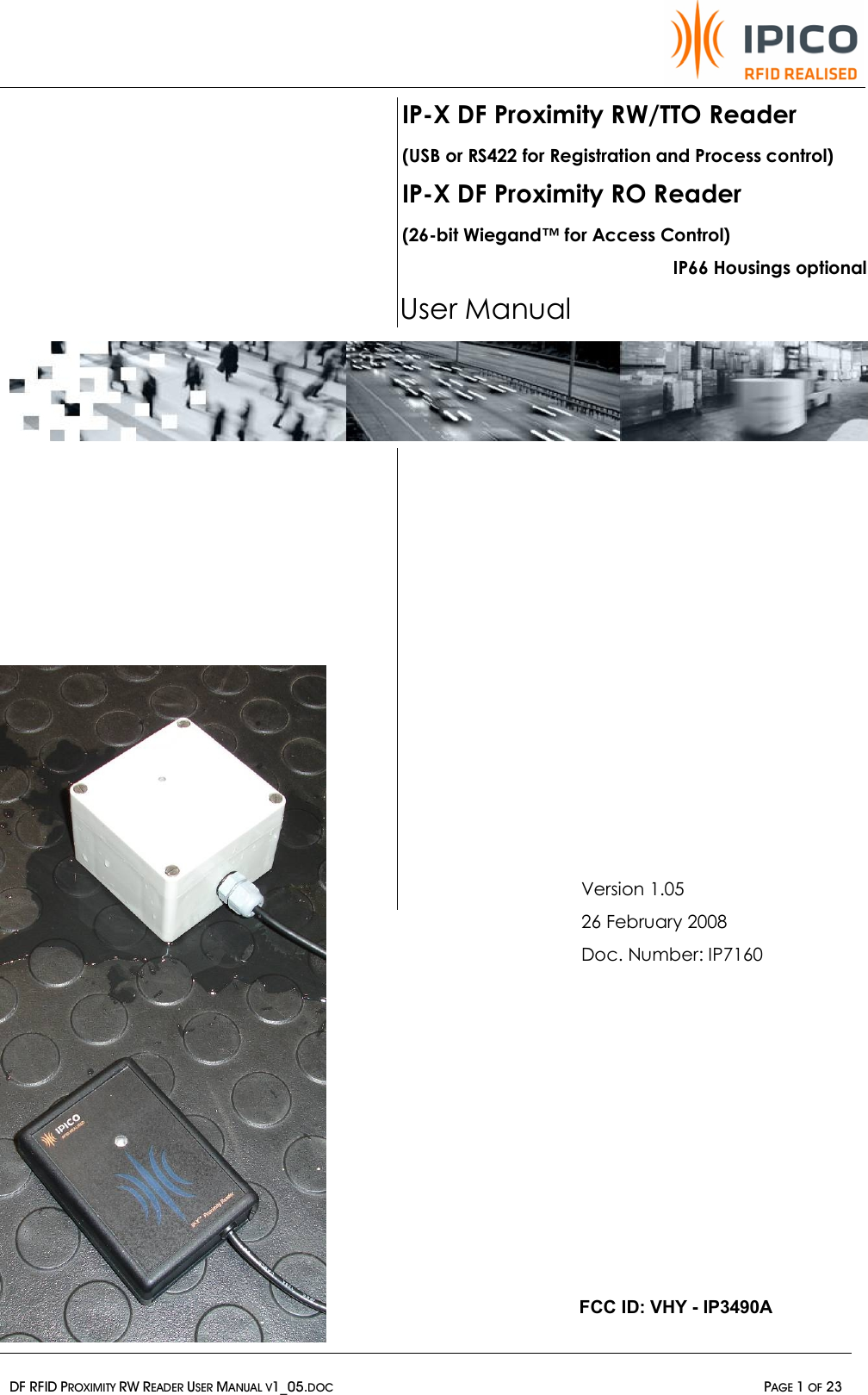
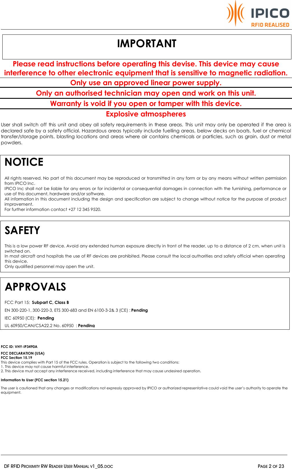
User Manual
Discussion / Help
Navigation