IP Mobilenet M64450G25 High Speed Mobile Radio User Manual 638402
IP Mobilenet, LLC High Speed Mobile Radio 638402
UserManual.wiki
>
IP Mobilenet
>
M64450G25 User Manual
>
Users Manual 2
Contents
1.
Users Manual 1
2.
Users Manual 2
3.
Users Manual 3
4.
Users Manual 4
5.
Users Manual 5
Users Manual 2
Navigation menu
Upload a User Manual
Namespaces
Wiki Guide
HTML
PDF
Info
Views
User Manual
Discussion / Help
Navigation
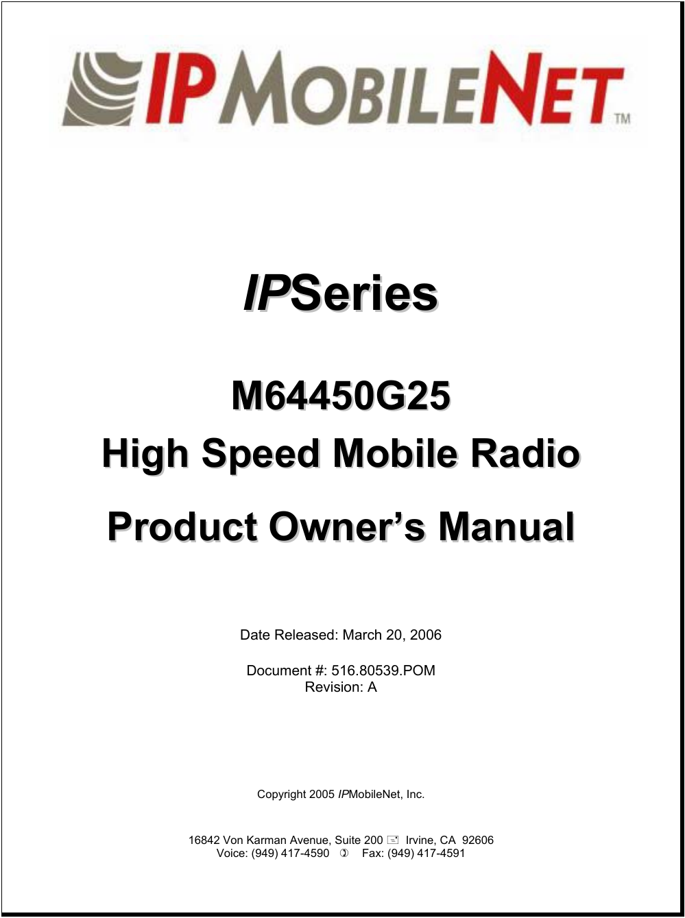
![SECTION 3: INSTALLATION INSTRUCTIONS M64450G25-FCCRpt.doc Page 22 # If a message window appears indicating the connection was unsuccessful, perform the following troubleshooting steps: 1. Ensure the serial and power cables are properly connected. 2. Verify that the mobile radio lock LED (light emitting diode) is on, indicating the mobile radio has power. 3. Ensure that the SLIP2IPMN dial-up connection is running. 4. If problem persists after retrying, replace the serial cable with one that is known to be working properly. Figure 15IPMessage Window Step 6 In the IPMessage window in the left field, enter the mobile radio’s IP address and press the [TAB] button. If the mobile radio IP address is not known, enter 255.255.255.255 in the left field. Step 7 In the right field type a ? and click the [ENTER] button. A list of mobile radio configuration parameters appears in the upper message window. This verifies that the IP address is correct, the mobile radio’s serial interface is live, and that the mobile radio’s microcontroller section is active. # If the upper message window only displays “To [IP address] ?”, communication has not been established. Validate the IP address. (Address)(Commands)](https://usermanual.wiki/IP-Mobilenet/M64450G25.Users-Manual-2/User-Guide-638402-Page-23.png)
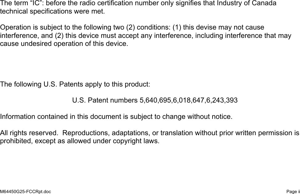
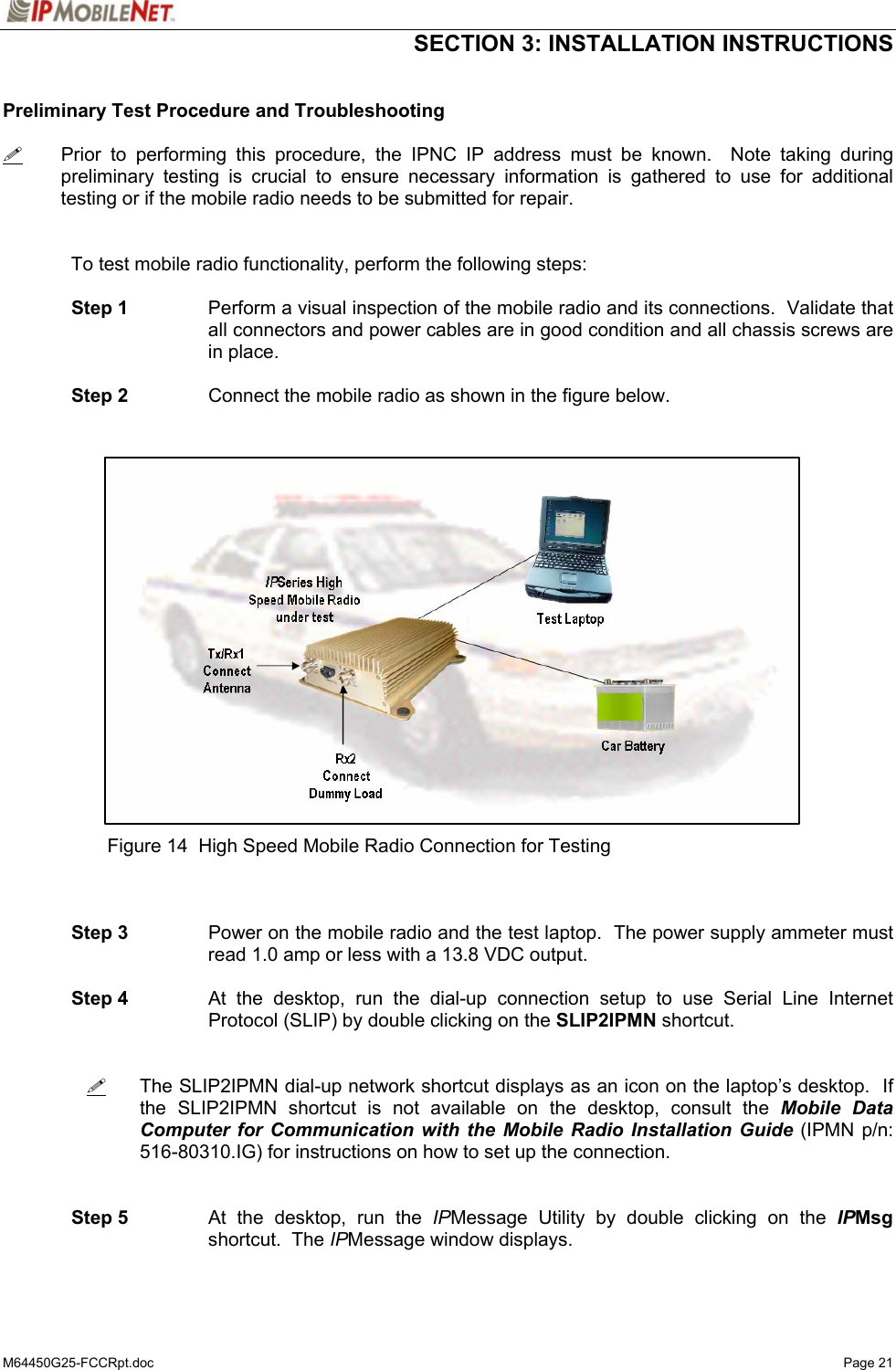
![SECTION 3: INSTALLATION INSTRUCTIONS M64450G25-FCCRpt.doc Page 23 Step 8 At the desktop, click on the Start button and select Programs and MS-DOS Prompt. The MS-DOS window displays. Step 9 Ping the IPNC commanding the transmitter to send 25 messages of 500 characters each to the IPNC as well as a response through Receiver 1 back to the laptop or desktop PC by typing in the following command at the MS-DOS prompt replacing NNN.NNN.NNN.NNN with the IPNC IP address: Ping NNN.NNN.NNN.NNN –n 25 –l 500 –w 4000 After entering the command, press [ENTER] to continue. When entering a command, pay special attention to the spaces and the characters being typed. # If the calibrated base station does not respond, check the syntax of the Ping command and verify the IP address is correct. If the ping command runs but high packet loss figures are shown, perform the following: 1. Verify that the calibrated base station and mobile radio antennae are separated by at least 10 feet. If the antennae are too close, the mobile radio receivers can be overloaded by the transmitters resulting in intermittent communication and high data errors. 2. Verify the calibrated base station parameters are correct for the mobile radio. Such parameters include IP addresses and complementary RX/TX frequencies. 3. Check to ensure the data and power cables are connected correctly. 4. If the Ping command continues to fail, test using a mobile radio that is known to be working properly. Step 10 Check the test laptop and verify that the Packets Lost Percentage is zero to 1% packet loss. Greater losses may indicate a problem with the transmitter/receiver 1, or modem circuitry. Step 11 Change the antenna on the mobile radio to the RX2 antenna input. Step 12 Connect the RF attenuator to the mobile radio’s TX/RX1 antenna input. Step 13 Connect the second antenna to the RF attenuator. In the IPMessage window, enter receiver=2. This will allow the mobile radio to only receive via Receiver 2. Step 14 Type the following command at the MS-DOS prompt replacing NNN.NNN.NNN.NNN with the IPNC IP address: Ping NNN.NNN.NNN.NNN –n 25 –l 500 –w 4000 After entering the command, press [ENTER] to continue. Step 15 Check the test laptop and verify that the Packets Lost Percentage is zero to 1% packet loss. Greater losses may indicate a problem with the receiver 2, or modem circuitry.](https://usermanual.wiki/IP-Mobilenet/M64450G25.Users-Manual-2/User-Guide-638402-Page-24.png)
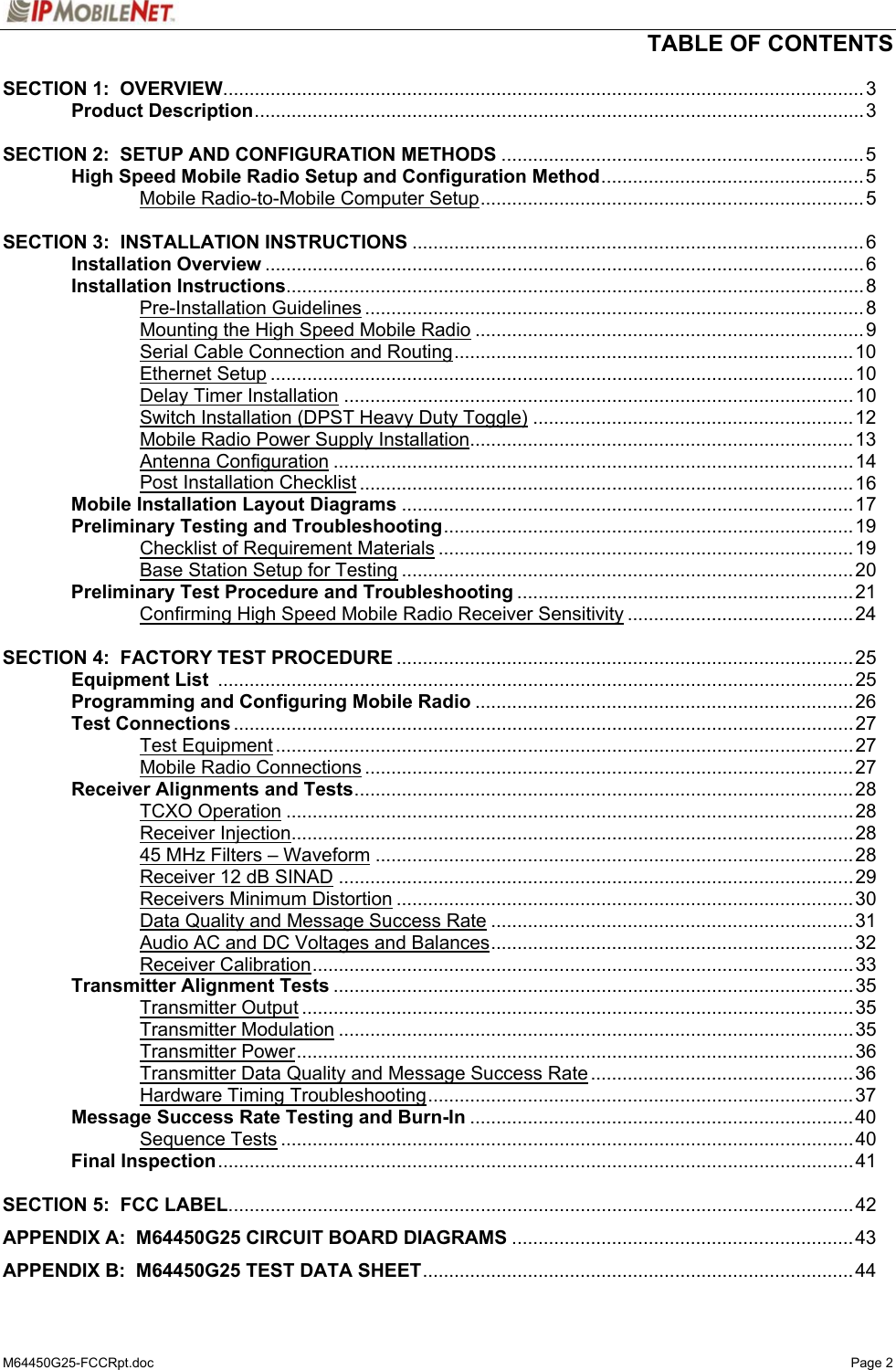
![SECTION 3: INSTALLATION INSTRUCTIONS M64450G25-FCCRpt.doc Page 24 Confirming High Speed Mobile Radio Receiver Sensitivity This set of instructions provides the user with a list of required equipment and steps needed to confirm mobile radio Receiver sensitivity. Requirements IPSeries High Speed Mobile Radio DC power supply, 13.8V, 12 amps or more (Astron VS 12M or equivalent) Desktop or laptop computer with IPMessage installed Agilent HP 8920A or B Service Monitor Serial cable DB9M – DB9F connectors (generic) To confirm mobile radio receiver sensitivity, perform the following steps: Step 1 Connect the mobile radio to the recommended power supply, the desktop or laptop computer, and the service monitor. Step 2 Turn on the mobile radio. Step 3 Connect the serial cable or Ethernet interface to the mobile radio and the desktop or laptop computer. Step 4 Start the connection to the mobile radio. Step 5 Start the IPMessage utility. Step 6 At the IPMessage window, enter the mobile radio IP address and press [ENTER]. Step 7 At the IPMessage window, enter unlock=password (entering the assigned password) and press [ENTER]. Step 8 Send the following test mode command at the IPMessage window, by entering testmode=1 and press [ENTER] to continue. Step 9 Generate an on frequency, modulated (1000 Hz @ 5 kHz dev) signal to Receiver 1 at –100 dBm. Step 10 At the IPMessage window, type noise and press [ENTER] to continue. Step 11 Confirm that the noise level for Receiver 1 is +/- 2dB of the –100 dBm level. Repeat the same steps for Receiver 2.](https://usermanual.wiki/IP-Mobilenet/M64450G25.Users-Manual-2/User-Guide-638402-Page-25.png)
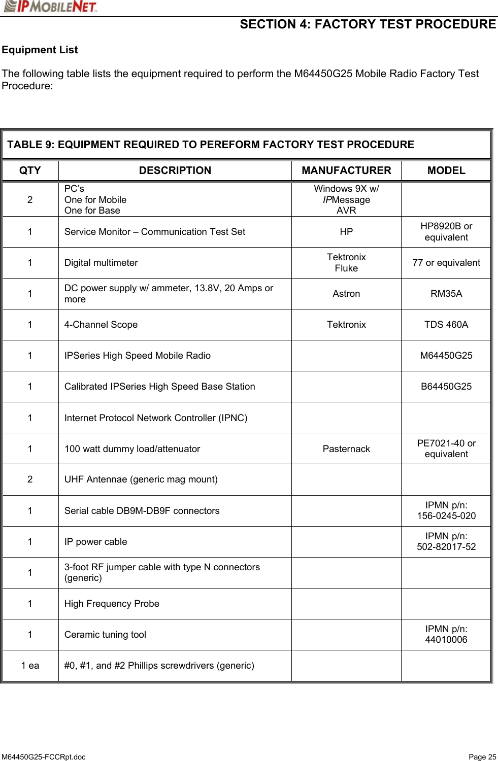
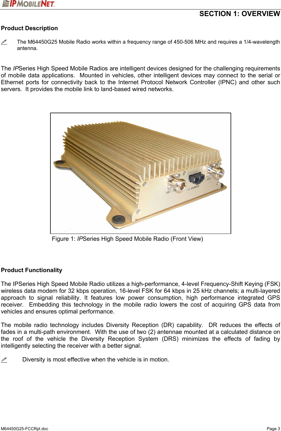
![SECTION 4: FACTORY TEST PROCEDURE M64450G25-FCCRpt.doc Page 26 Programming and Configuring Mobile Radio Once the appropriate equipment for performing the factory test are gathered, perform the following steps to program and configure an M64450G25 Mobile Radio: Step 1 Enter the mobile radio serial number, date test being performed, and tester’s name on the Test Data Sheet (see Appendix B). Step 2 Program the radio to the current Firmware revision using the AVR programming utility. Step 3 Connect a PC to the radio and launch the IPMessage program. In the IPMessage window, type factory default, press [ENTER], and the radio displays the radio’s default values. Step 4 Enter the appropriate values for the radio's frequency band. The following values were used for a 450-506 MHz mobile radio: Frequency= 0, 450.000000, 463.000000, 418.000000](https://usermanual.wiki/IP-Mobilenet/M64450G25.Users-Manual-2/User-Guide-638402-Page-27.png)
![SECTION 4: FACTORY TEST PROCEDURE M64450G25-FCCRpt.doc Page 27 Test Connections Test Equipment Setup The test equipment should be configured as shown in the figure below: Mobile Radio Connections Perform the following steps to connect the mobile radio properly: Step 1 Connect the GPS antenna. Step 2 Connect a serial cable and launch IPMessage. Step 3 Connect a load to the transmitter antenna port. Step 4 Connect the power cable to a voltage source of 13.8 VDC able to deliver 25 amps of continuous current. Step 5 Apply power to the mobile radio. Step 6 Verify the IPMessage connection by entering the “?” in the IPMessage command field and pressing [ENTER].](https://usermanual.wiki/IP-Mobilenet/M64450G25.Users-Manual-2/User-Guide-638402-Page-28.png)
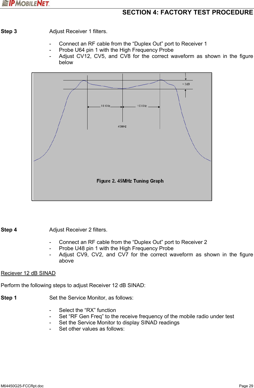
![SECTION 4: FACTORY TEST PROCEDURE M64450G25-FCCRpt.doc Page 28 Receiver Alignments and Tests TCXO Operation Perform the following steps to check the operation of the TCXO: Step 1 In IPMessage, type “status = pps, cal” in the command field and press [ENTER]. Step 2 Read the reported error values for the TCXOs. Step 3 Continue using the “status = pps, cal” command, until GPS is acquired. Step 4 Repeat the command observing the error values. Step 5 Observe that the TCXO “error ppb” continues to adjust until it settles at +/-200. Step 6 Enter the “error ppb” data onto the Tune and Align Data Sheet. Receiver Injection Perform the following steps to make sure the receiver injection is locked on frequency: Step 1 Connect a coaxial cable from the Service Monitor “RF Input” port to the “RX2” port on the mobile radio. Step 2 Place the Service Monitor in the “Tx” mode. Step 3 Set the Service Monitor to the base station’s Receiver Injection frequency. Step 4 Adjust the squelch on the Service Monitor until the frequency error is displayed. Step 5 When the injection frequency stabilizes record the frequency error on the Tune and Align Data Sheet. At this time the Operator is able to proceed with the other adjustments and alignments. 45 MHz Filters Waveform Perform the following steps to set the Waveform for the 45 MHz filters: Step 1 Set the Service Monitor with the following selections: - Select the spectrum analyzer function - Set the center frequency for 45 MHz - Set the amplitude to -20 dBm - Set the Span to 100 kHz - Choose “Controls…RF Gen” - Set to “Track” to enable the tracking generator - Set the “RF Gen Freq” to equal the radio receive frequency minus 45 MHz - Set “Amplitude” to -30 dBm - Set the “Output Port” to “DUPL” to select the duplex out port Step 2 Connect a High Frequency Probe to “Ant In” port on the Service Monitor.](https://usermanual.wiki/IP-Mobilenet/M64450G25.Users-Manual-2/User-Guide-638402-Page-29.png)