IP Mobilenet IPM4748 IPM4 Mobile Radio User Manual 516 80495 UM IPM MR
IP Mobilenet, LLC IPM4 Mobile Radio 516 80495 UM IPM MR
UserManual.wiki
>
IP Mobilenet
>
IPM4748 User Manual
>
Installation manual
Contents
1.
User Manual
2.
Installation manual
Installation manual
Navigation menu
Upload a User Manual
Namespaces
Wiki Guide
HTML
PDF
Info
Views
User Manual
Discussion / Help
Navigation

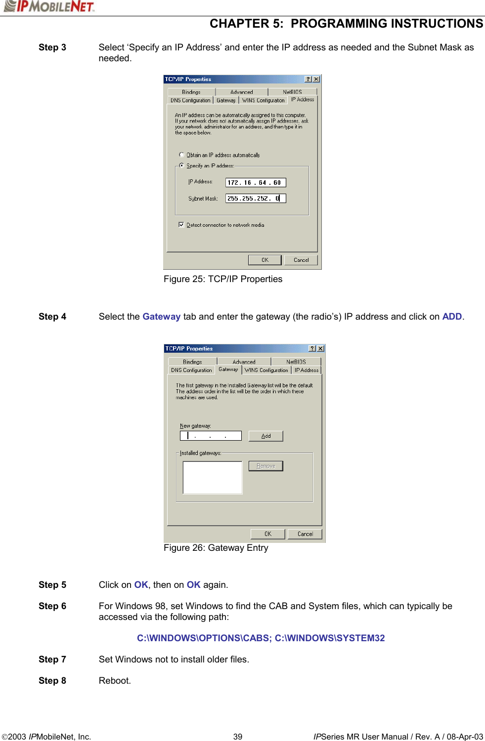
![CHAPTER 4: PRODUCT INSTALLATION 2003 IPMobileNet, Inc. 36 IPSeries MR User Manual / Rev. A / 08-Apr-03 # If a message window appears indicating the connection was unsuccessful, perform the following troubleshooting steps: 1. Ensure the serial and power cables are properly connected. 2. Verify that the mobile radio lock LED (light emitting diode) is on, indicating the mobile radio has power (see Figure 2). 3. Ensure that the IPMN_INVADR dial-up connection is running. 4. If problem persists after retrying, replace the serial cable with one that is known to be working properly. Figure 22: IPMessage Window Step 6 In the IPMessage window in the left field, enter the mobile radio’s IP address and press the TAB button. If the mobile IP address is not known, enter 255.255.255.255 in the left field. Step 7 In the right field type a ? and click the ENTER button. A list of mobile radio configuration parameters appears in the upper message window. This verifies that the IP address is correct, the mobile radio’s serial interface is live, and that the mobile radio’s microcontroller section is active. # If the upper message window only displays “To [IP address] ?”, communication has not been established. Validate the IP address. (Address)(Commands)](https://usermanual.wiki/IP-Mobilenet/IPM4748.Installation-manual/User-Guide-332755-Page-36.png)
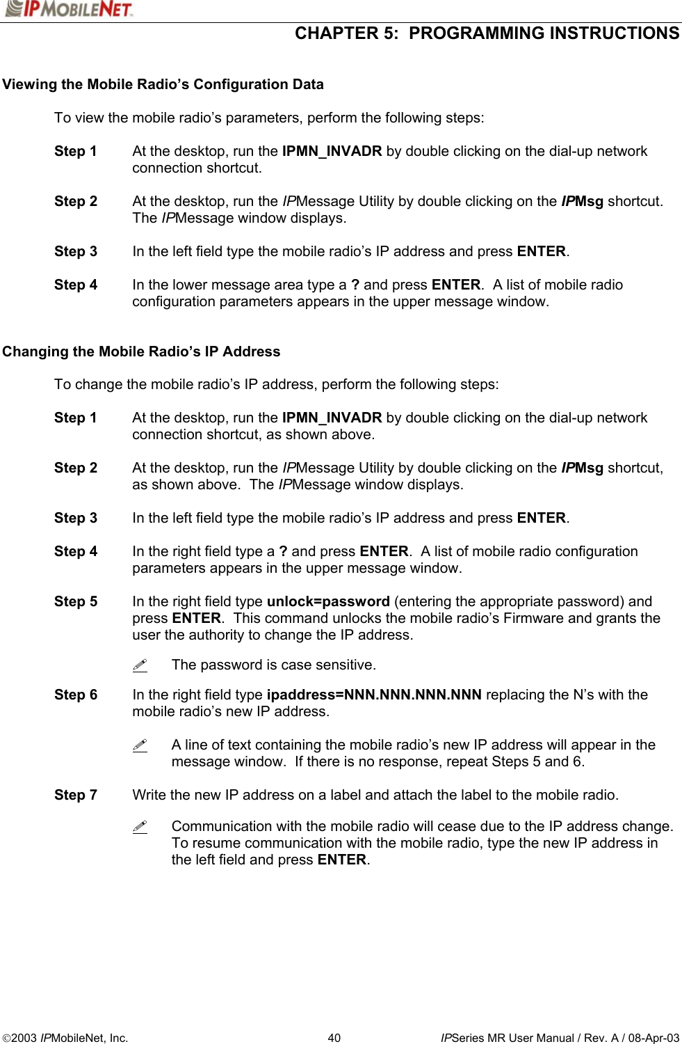
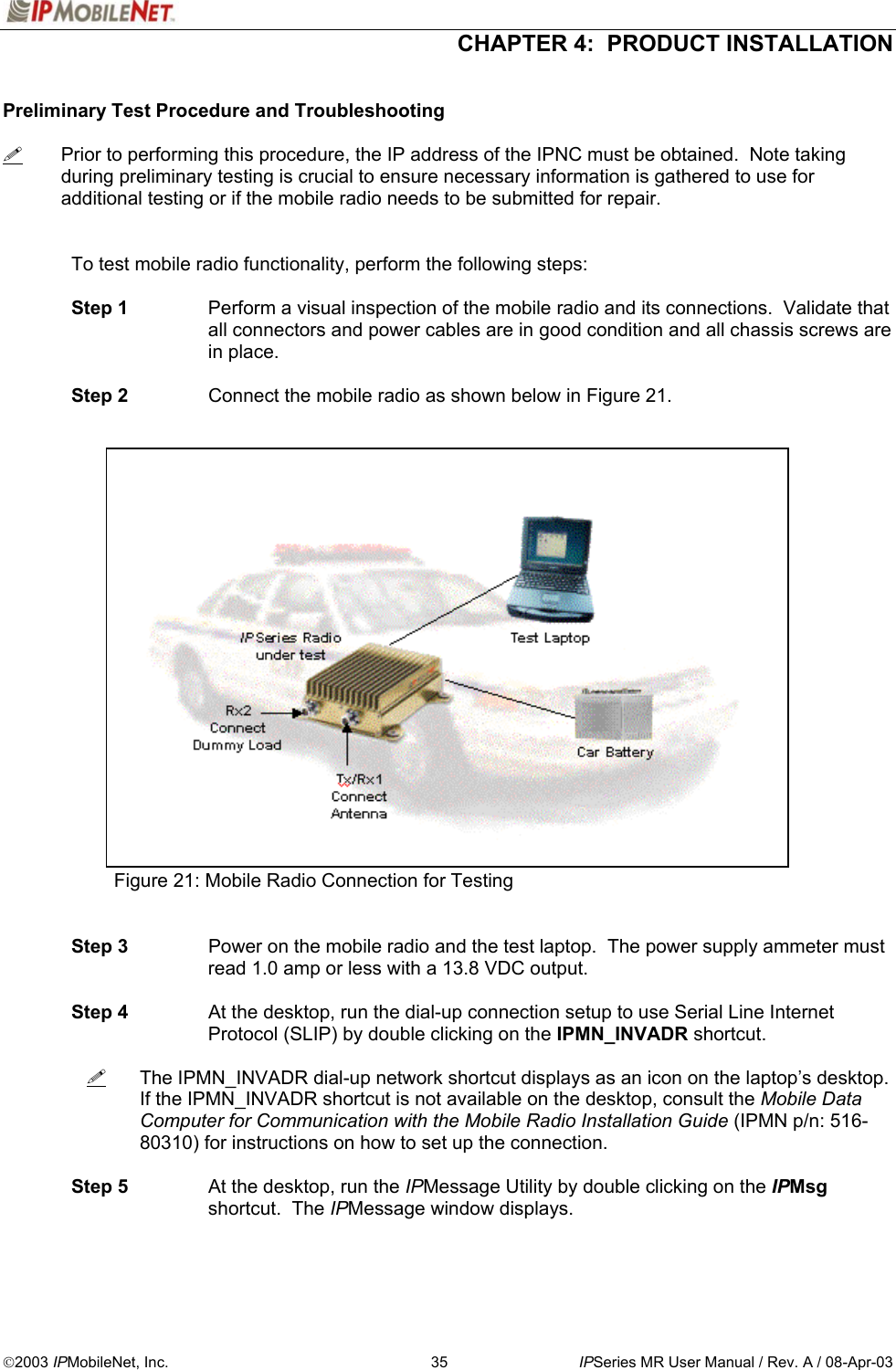
![CHAPTER 4: PRODUCT INSTALLATION 2003 IPMobileNet, Inc. 37 IPSeries MR User Manual / Rev. A / 08-Apr-03 Step 8 At the desktop, click on the Start button and select Programs and MS-DOS Prompt. The MS-DOS window displays. Step 9 Ping the IPNC commanding the transmitter to send 25 messages of 500 characters each to the IPNC as well as a response through Receiver 1 back to the laptop or desktop PC by typing in the following command at the MS-DOS prompt replacing NNN.NNN.NNN.NNN with the IPNC IP address: Ping NNN.NNN.NNN.NNN –n 25 –l 500 –w 4000 After entering the command, press [ENTER] to continue. When entering a command, pay special attention to the spaces and the characters being typed. # If the calibrated base station does not respond, check the syntax of the Ping command and verify the IP address is correct. If the ping command runs but high packet loss figures are shown, perform the following: 1. Verify that the calibrated base station and mobile radio antennas are separated by at least 10 feet. If the antennas are too close, the mobile radio receivers overload by the transmitters resulting in intermittent communication and high data errors. 2. Verify the calibrated base station parameters are correct for the mobile radio. Such parameters include IP addresses and complementary RX/TX frequencies. 3. Check to ensure the data and power cables are connected correctly. 4. If the Ping command continues to fail, test using a mobile radio that is known to be working properly. Step 10 Check the test laptop and verify that the Packets Lost Percentage is zero to 1% packet loss. Greater losses may indicate a problem with the transmitter/receiver 1, or modem circuitry. Step 11 Change the antenna on the mobile radio to the RX2 antenna input. Step 12 Connect the RF attenuator to the mobile radio’s TX/RX1 antenna input. Step 13 Connect the second antenna to the RF attenuator. In the IPMessage window, enter receiver=2. This will allow the mobile radio to only receive via Receiver 2. Step 14 Type the following command at the MS-DOS prompt replacing NNN.NNN.NNN.NNN with the IPNC IP address: Ping NNN.NNN.NNN.NNN –n 25 –l 500 –w 4000 After entering the command, press [ENTER] to continue. Step 15 Check the test laptop and verify that the Packets Lost Percentage is zero to 1% packet loss. Greater losses may indicate a problem with the transmitter/receiver 1, or modem circuitry.](https://usermanual.wiki/IP-Mobilenet/IPM4748.Installation-manual/User-Guide-332755-Page-37.png)