IP COM NETWORKS AP375 Wireless Access Point User Manual
SHENZHEN IP-COM NETWORKS CO.,LTD. Wireless Access Point
UserManual.wiki
>
IP COM NETWORKS
>
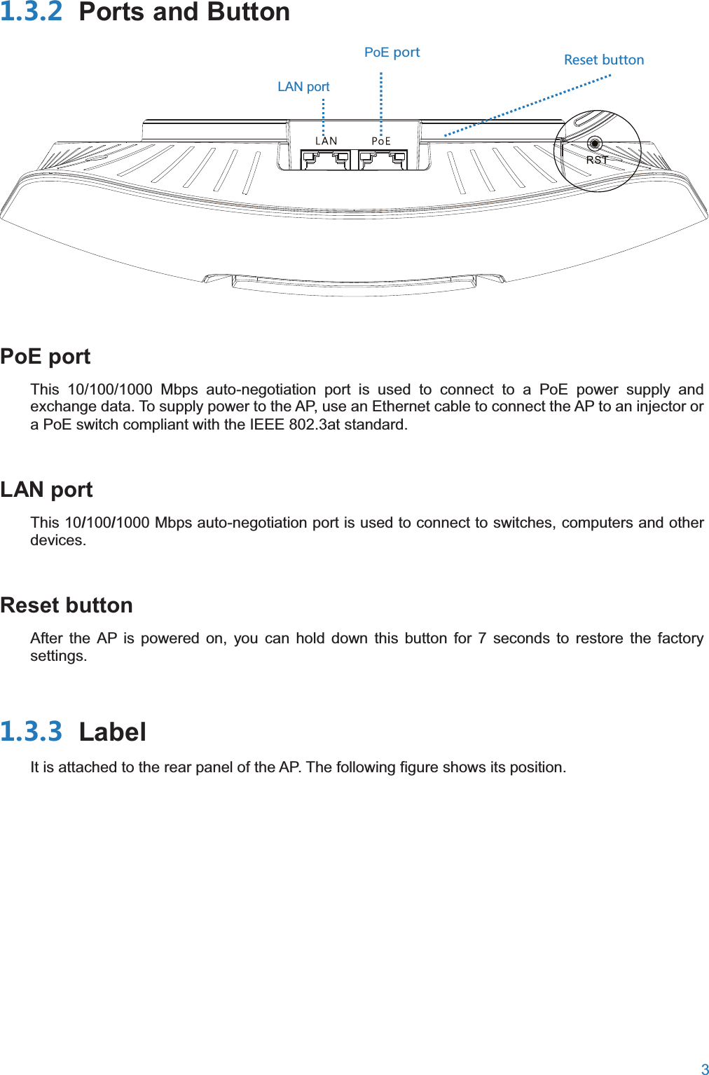
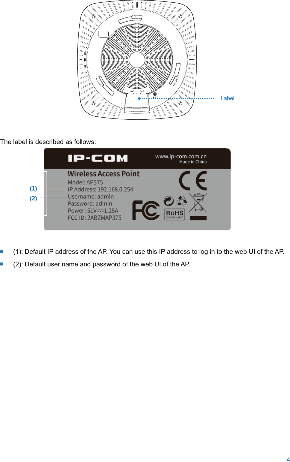
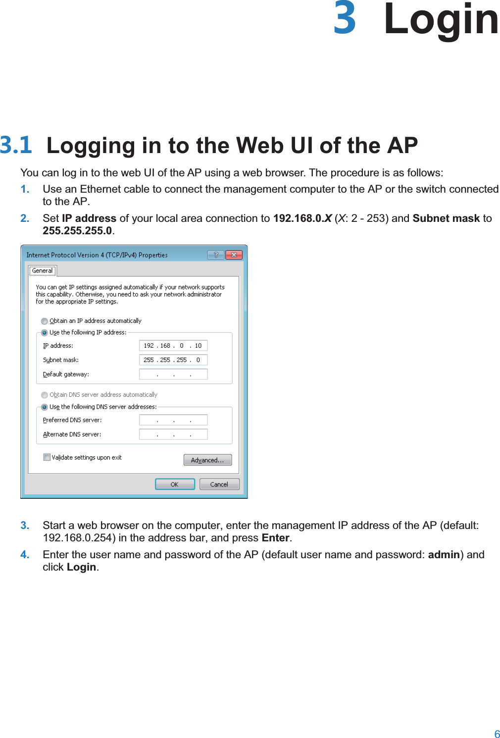
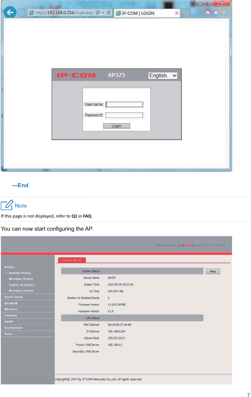
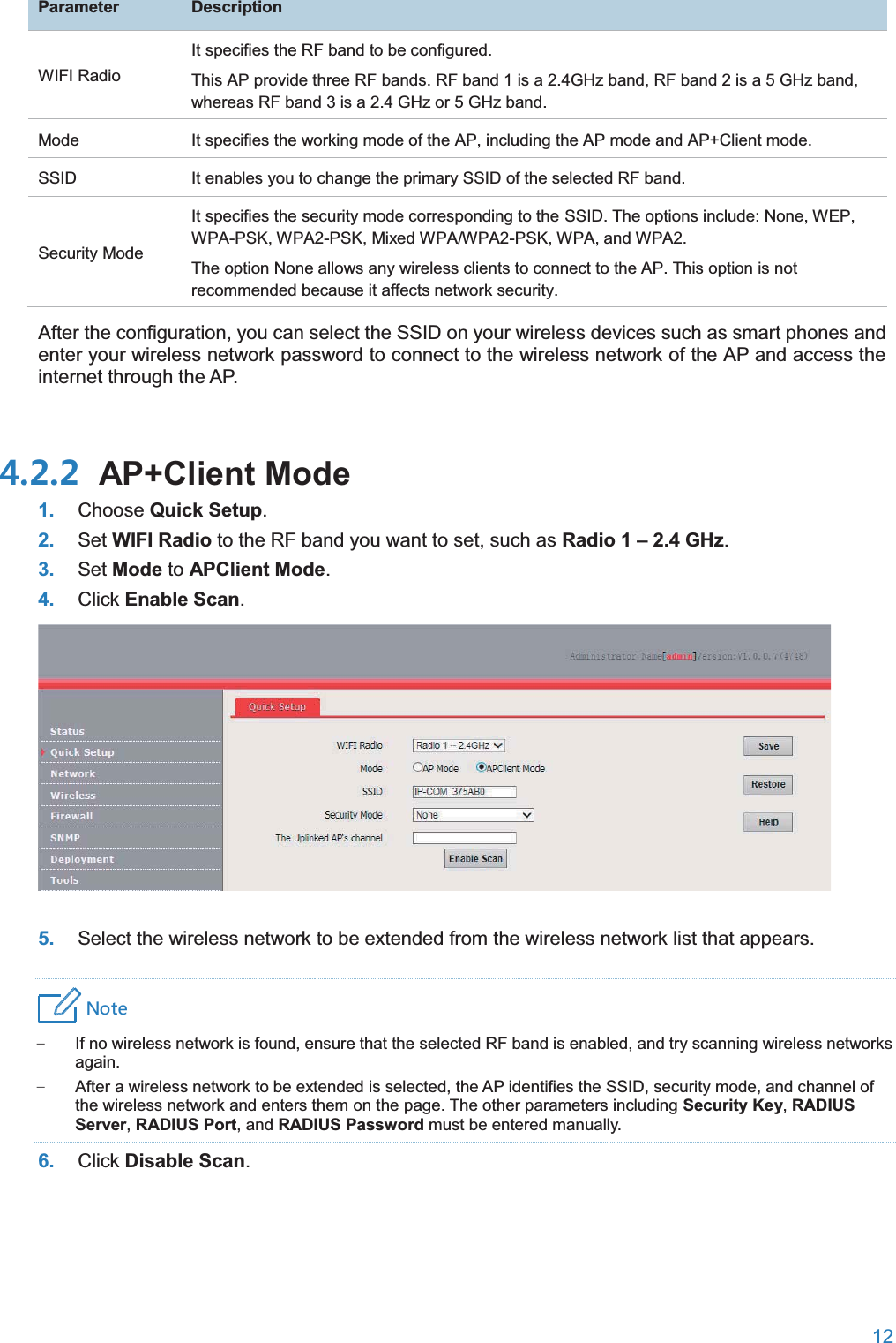
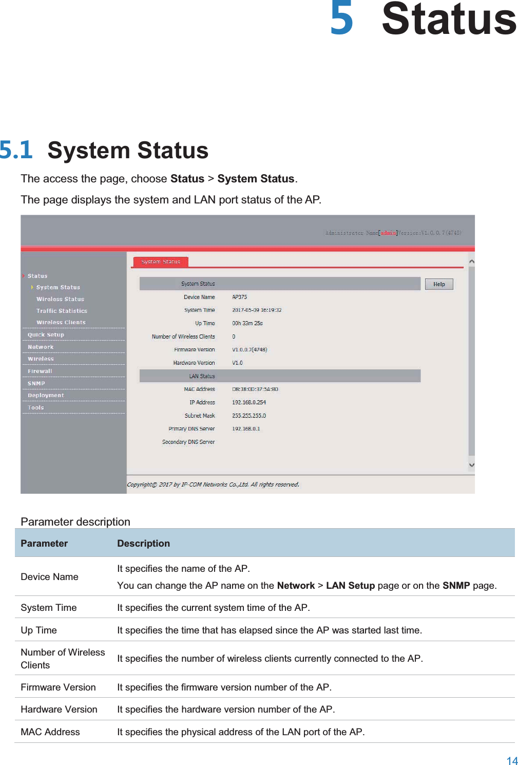
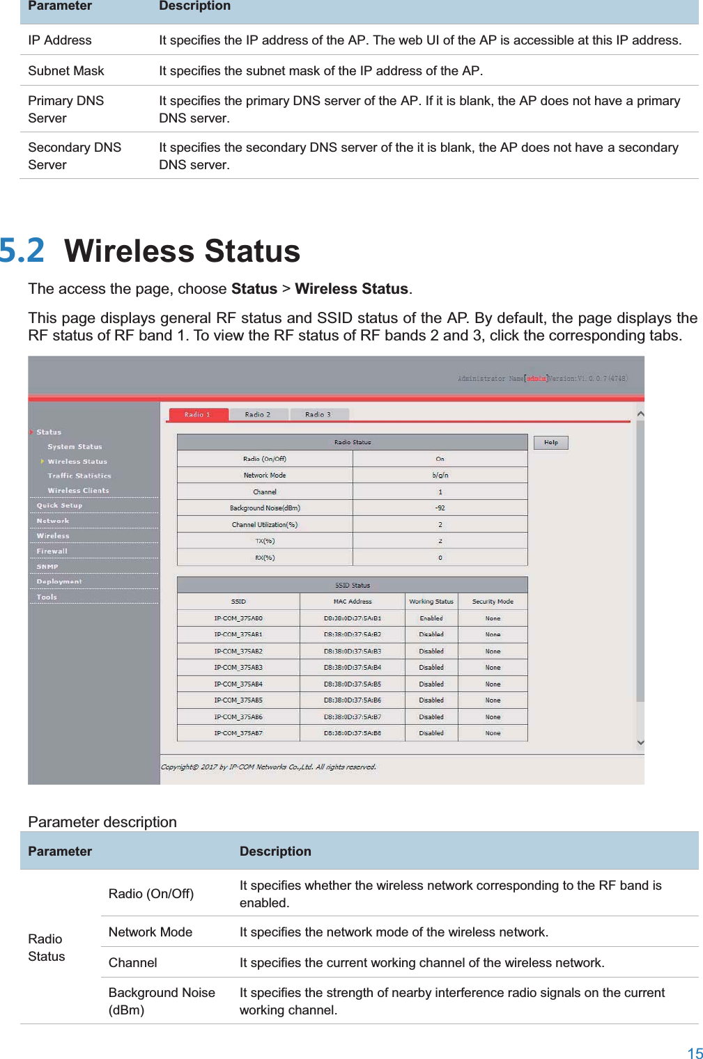
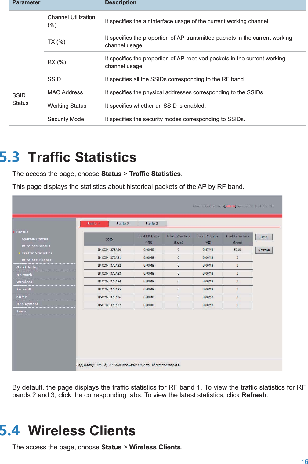
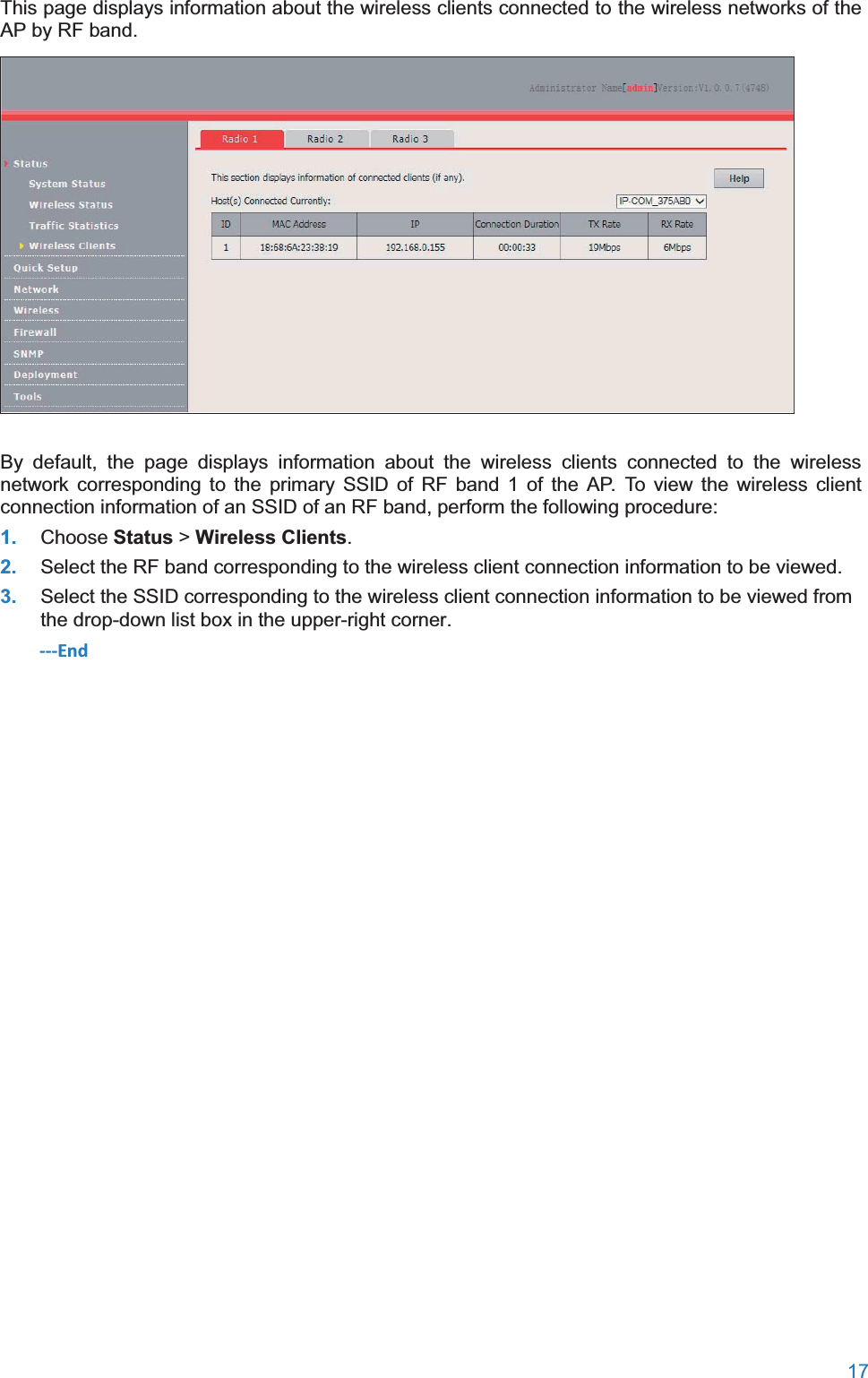
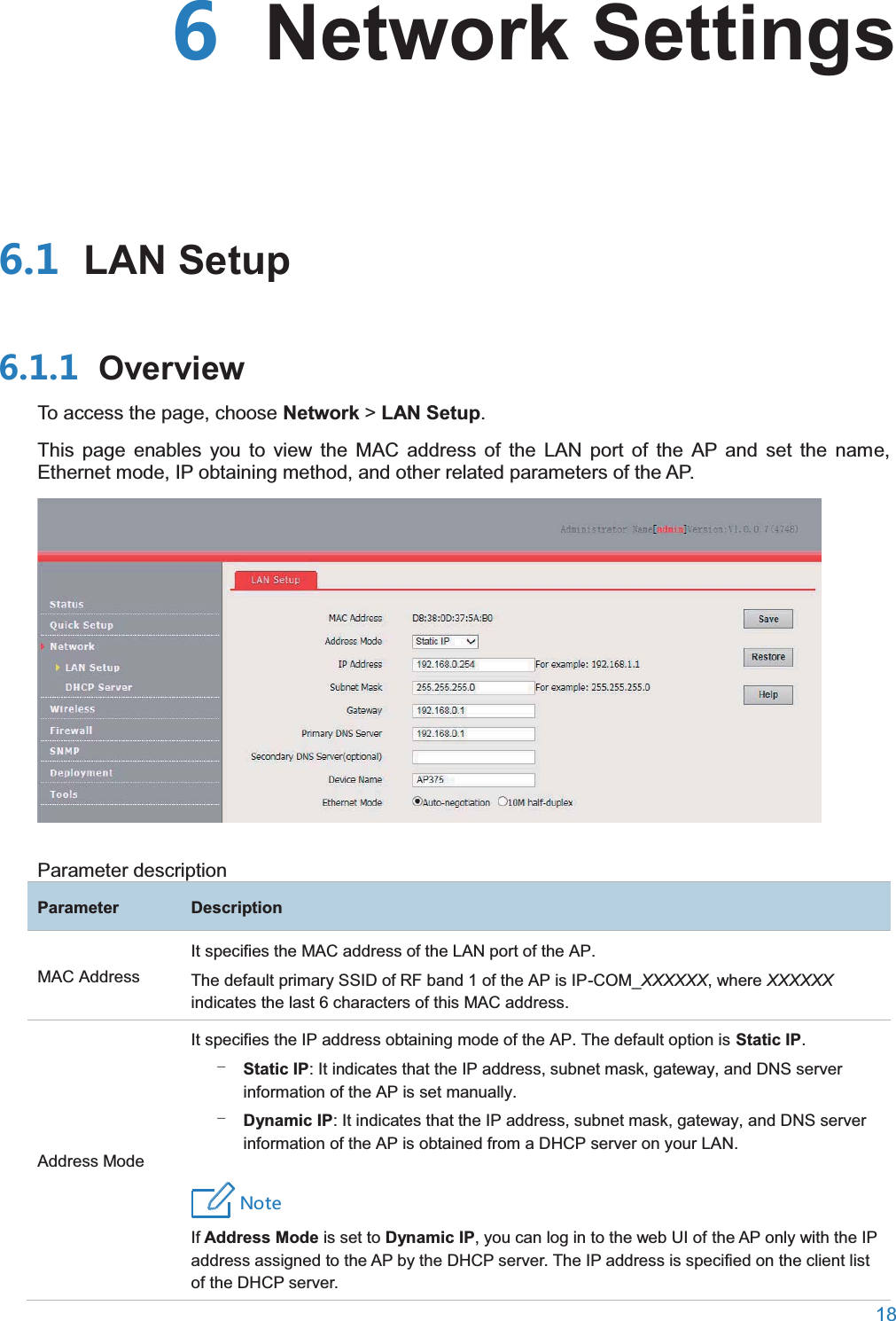
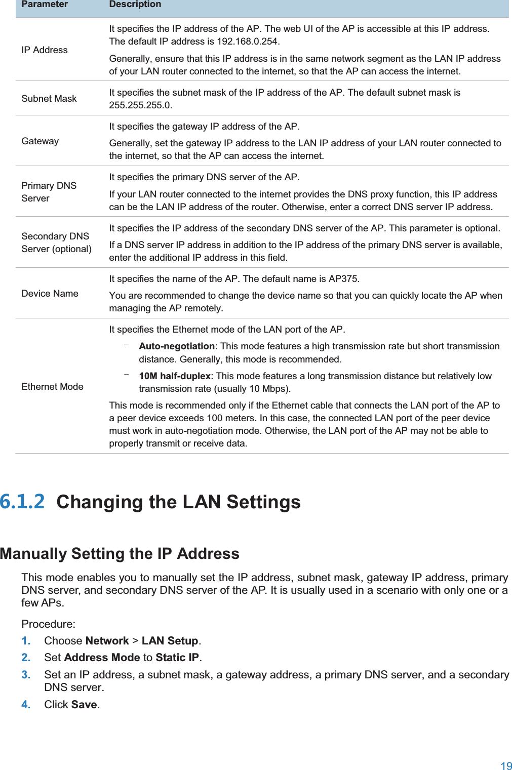
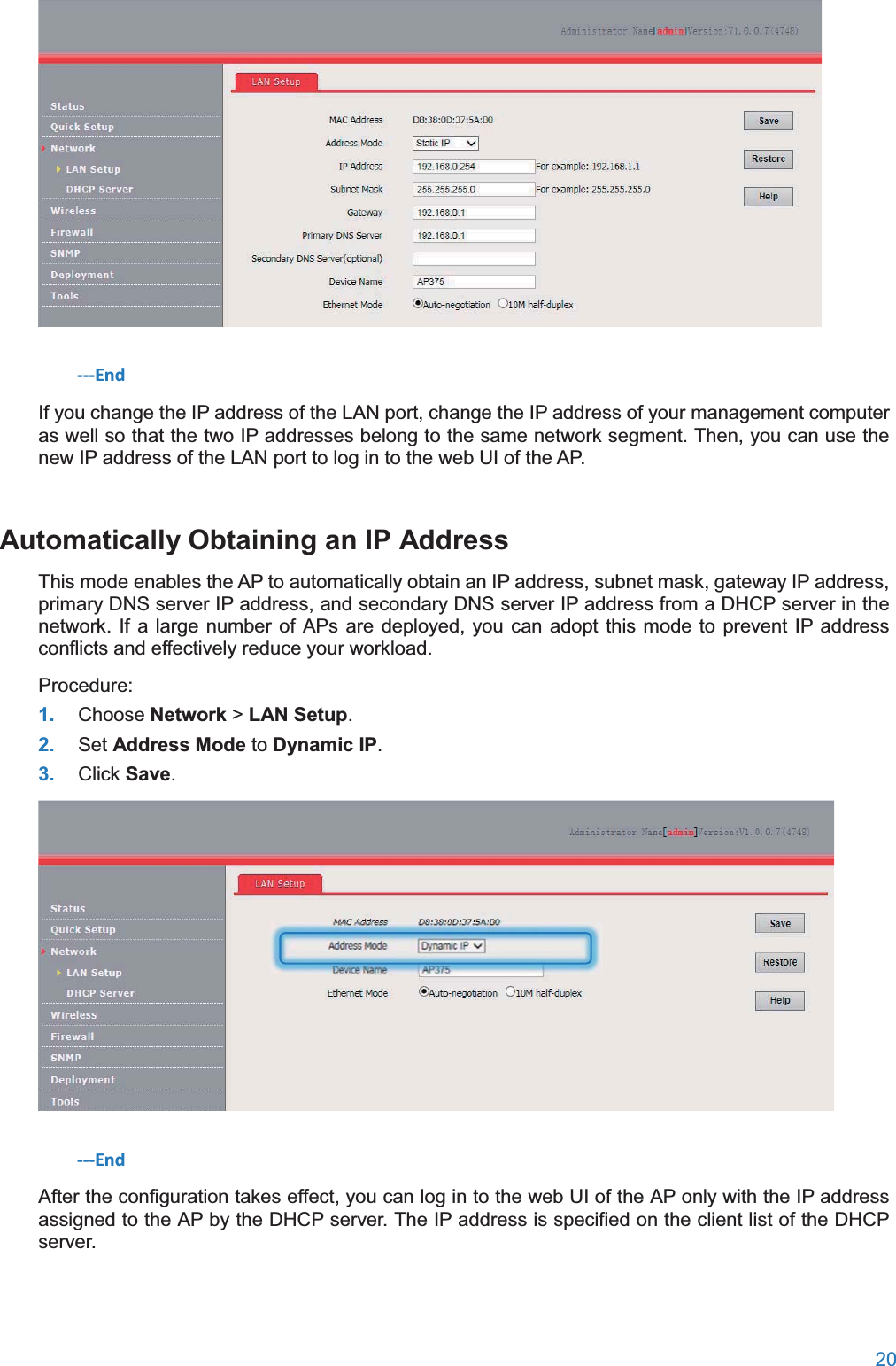
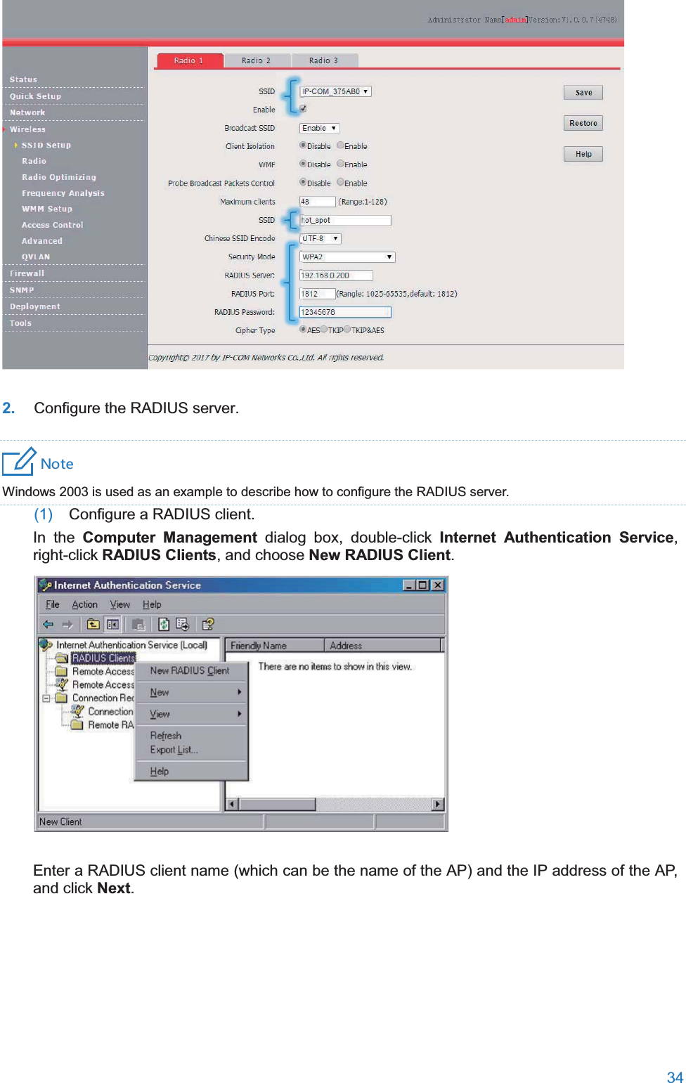
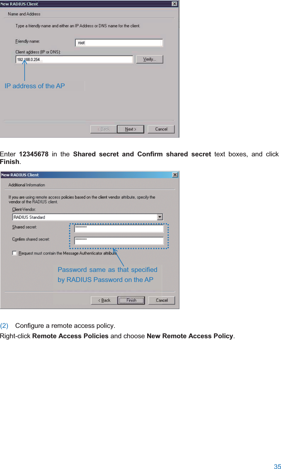
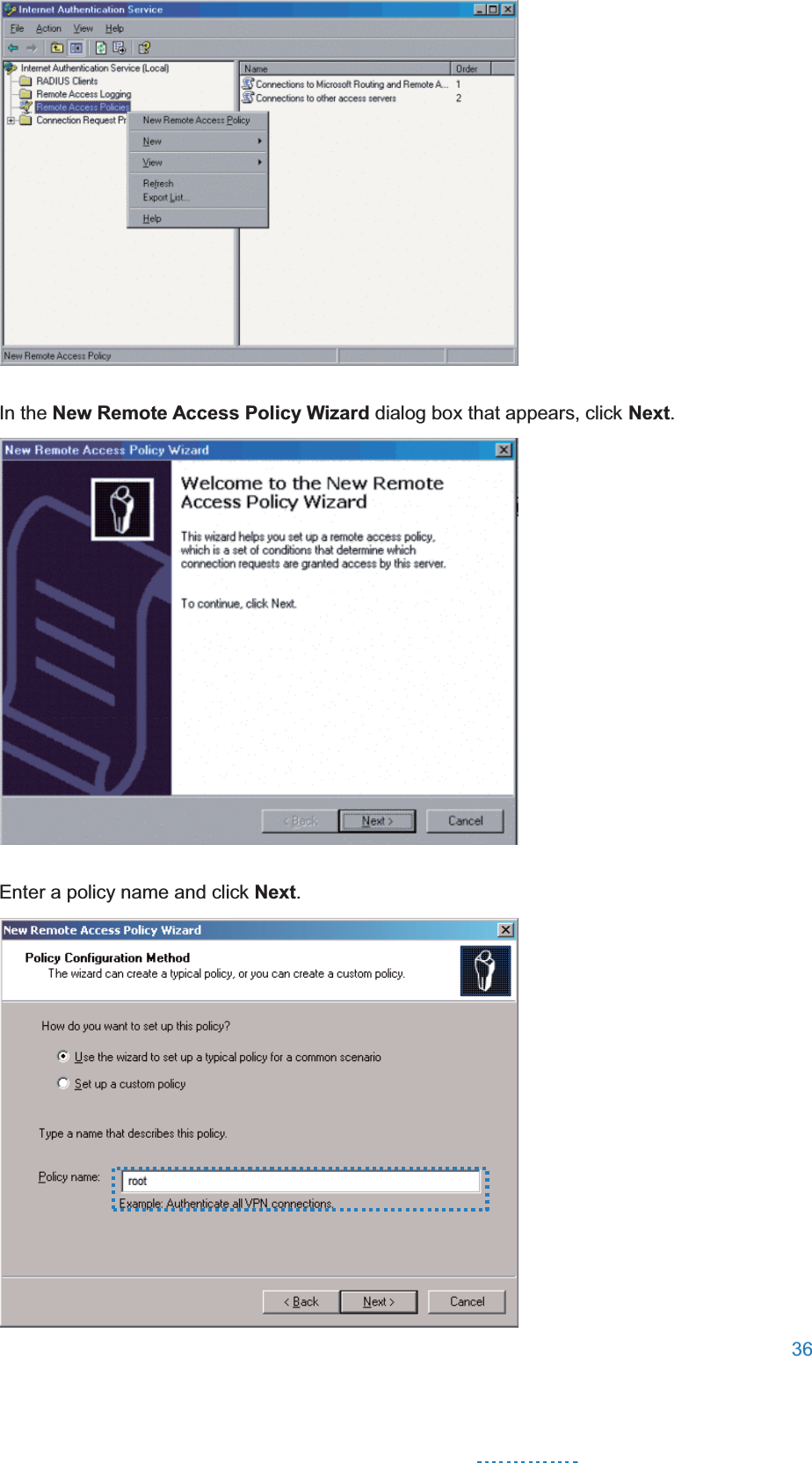
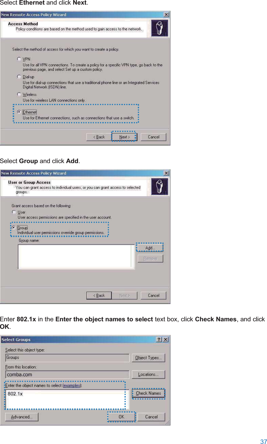
AP375 User Manual
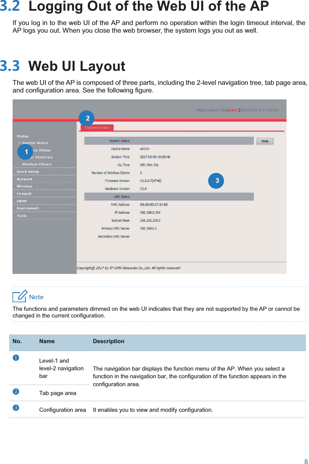
User Manual
Navigation menu
Upload a User Manual
Namespaces
Wiki Guide
HTML
PDF
Info
Views
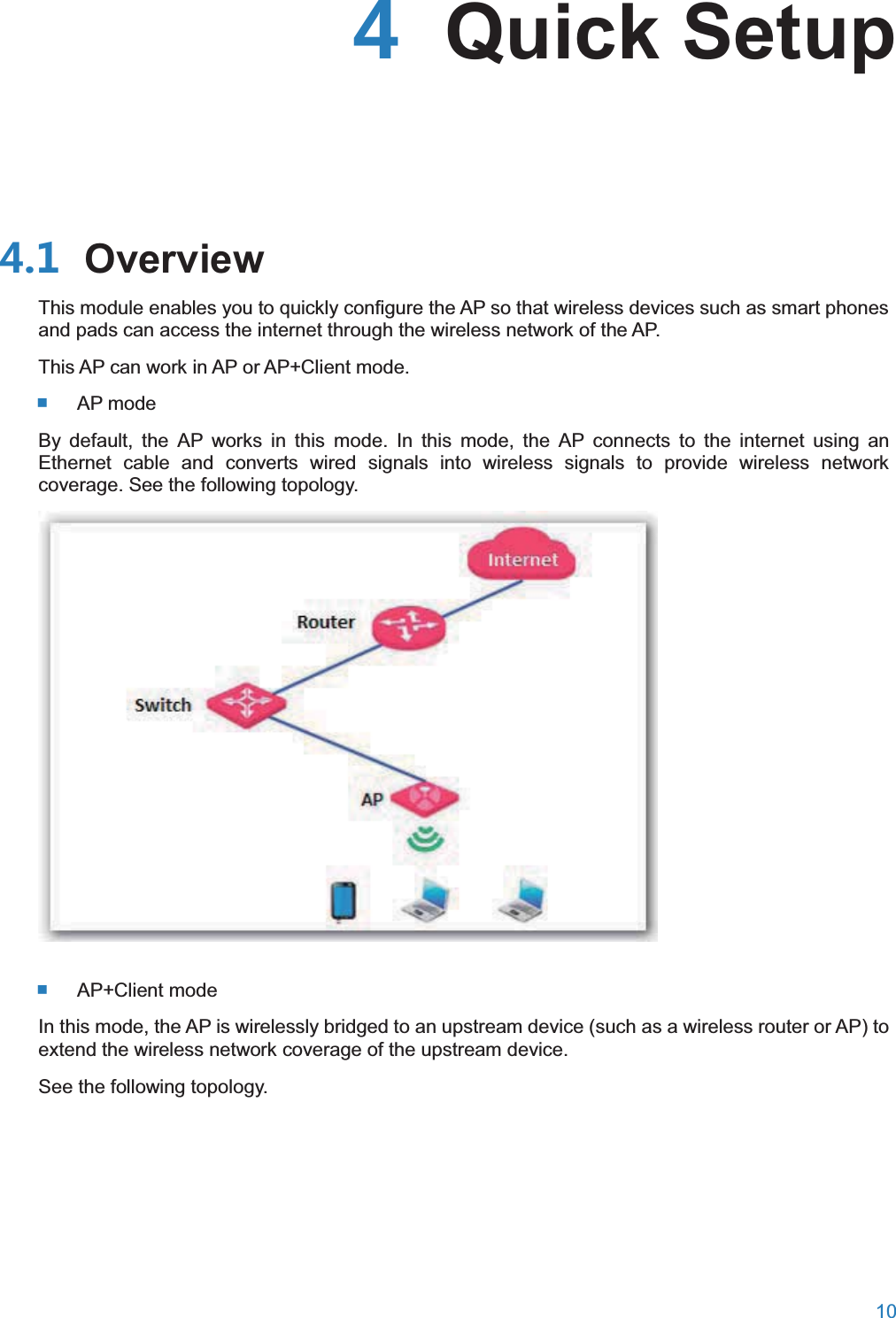
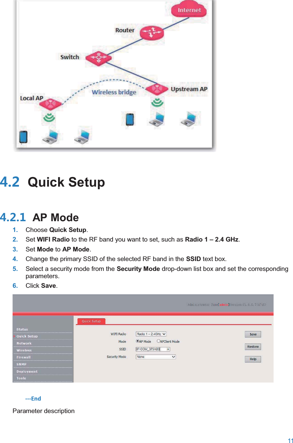
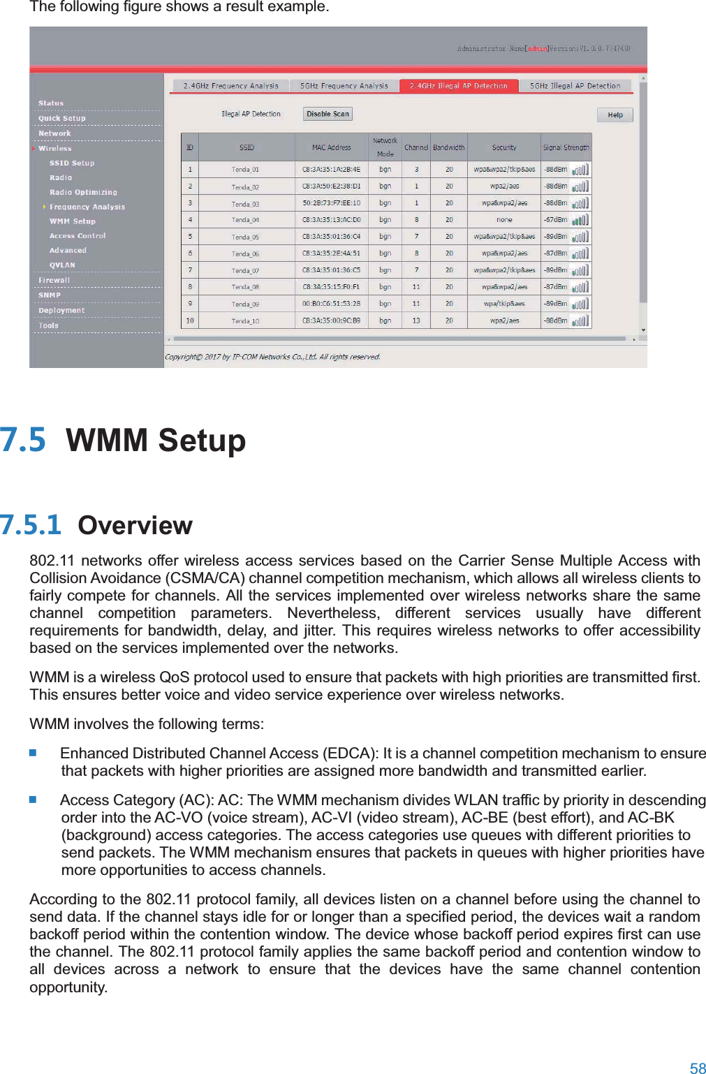
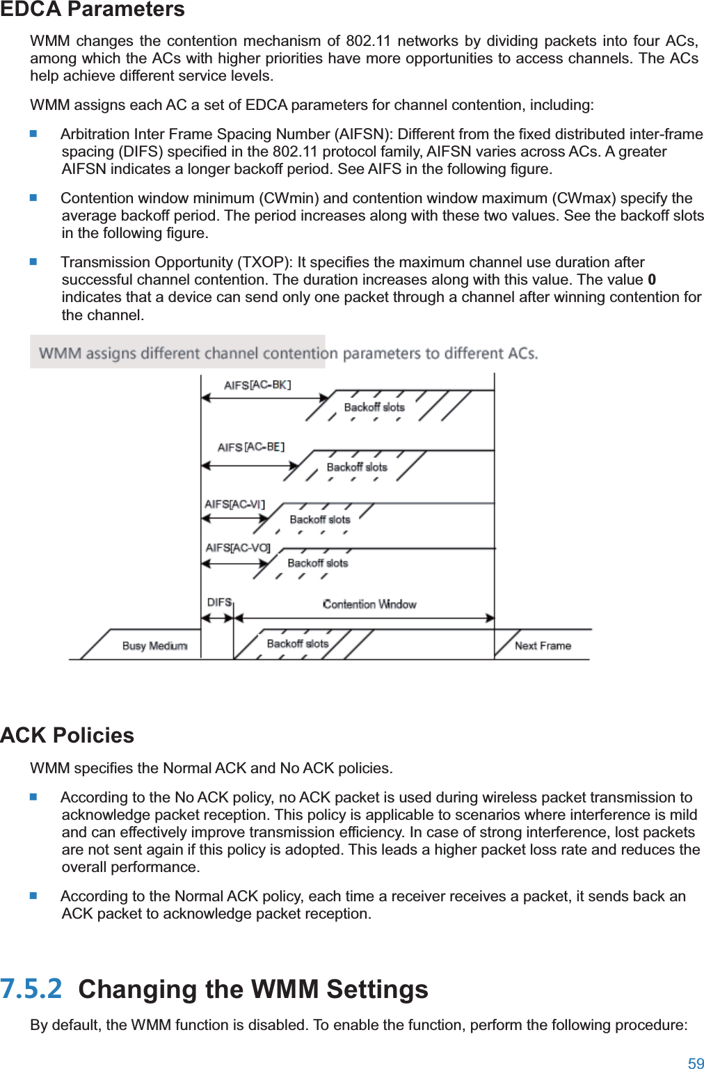
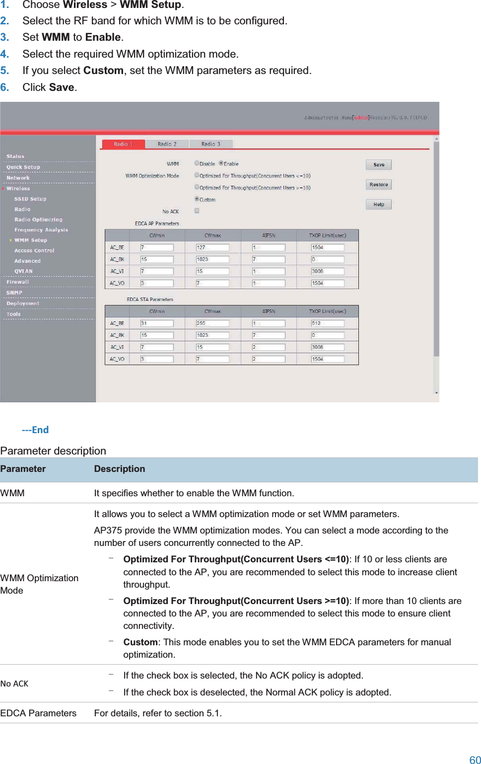
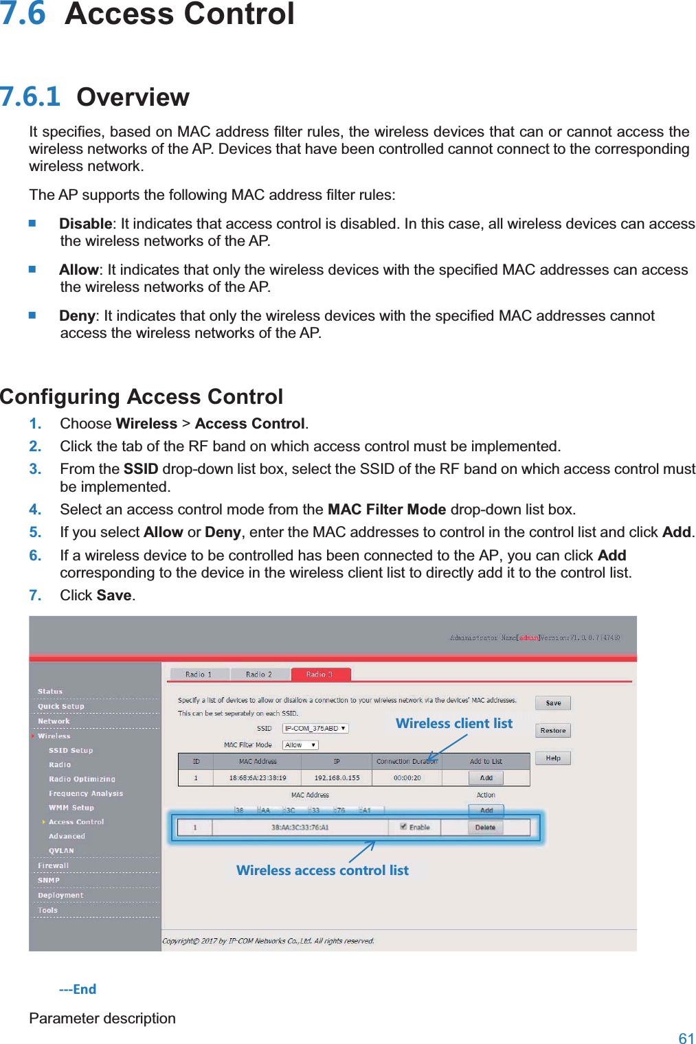
User Manual
Discussion / Help
Navigation