ICOM orporated 282600 VHF Scanning Receiver User Manual IC V82 11
ICOM Incorporated VHF Scanning Receiver IC V82 11
UserManual.wiki
>
ICOM orporated
>
282600 User Manual
>
Users Manual Part 2
Contents
1.
Users Manual Part 1
2.
Users Manual Part 2
Users Manual Part 2
Navigation menu
Upload a User Manual
Namespaces
Wiki Guide
HTML
PDF
Info
Views
User Manual
Discussion / Help
Navigation
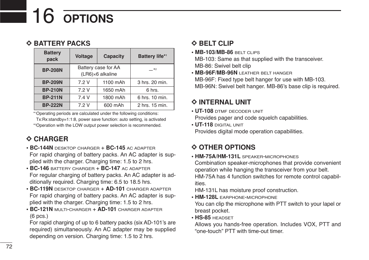
![318SCAN OPERATION8DMemory scan watchWhile operating on a VFO frequency or the call channel, mem-ory scan watch monitors for signals in each memory channelin sequence, every 5 sec.qPush [C•MR]to select memory mode, if necessary.•“X” appears.wPush [A•FUNC], then push [5•SCAN]to start the memoryscan.ePush [A•FUNC], then push [7•PRIO]to start the watching.•VFO is displayed, then the decimal point “.”, on the frequencyreadout blinks.• When the signal is detected on the priority channel, the watchingis paused according to the setting of the scan resume condition.rPush [D•CLR]to stop the watching.■Scan resume conditionWhen a signal is received during scanning, the scan resumecondition determines what action the transceiver takes. Thetransceiver has 2 scan resume conditions available asillustrated below. UseSET MODEto select the one which bestsuits your needs.qPush [A•FUNC], then push [8•SET]to enter SET MODE.wPush [YY]or [ZZ]several times until “SCP” or “SCt” ap-pears.eRotate [VOL] to select the desired scan resume condition.•Pause scan:When receiving a signal, scan pauses onthe signal until it disappears. Resumes 2sec. after the signal disappears. •Timer scan:When receiving a signal, scan pauses onthe signal for 5 sec., 10 sec. or 15 sec.,then resumes.rPush [✱•ENT](or [D•CLR])to set and exit SET MODE.Timer scanPause scanUSINGSET MODE](https://usermanual.wiki/ICOM-orporated/282600.Users-Manual-Part-2/User-Guide-486360-Page-1.png)
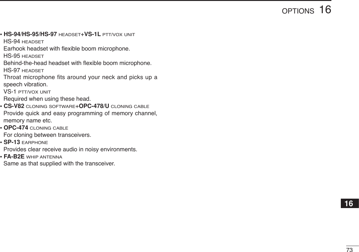
![■Tone squelchDOperationThe tone squelch opens only when receiving a signal con-taining a matching subaudible tone. You can silently wait forcalls from group members using the same tone.qSet the operating frequency.• Set the AF and squelch to the desired level as the normal opera-tion.wSet the desired subaudible tone in SET MODE.• See page 32 for programming.ePush [A•FUNC], then push [1•TONE].•Repeat several times until “ ” appears when selecting CTCSS,or “ ” appears when selecting DTCS.rWhen the received signal includes a matching tone,squelch opens and the signal can be heard.• When the received signal’s tone does not match, tone squelchdoes not open, however, the S-indicator shows signal strength.• To open the squelch manually, push and hold [MONI].tOperate the transceiver in the normal way.yTo cancel the tone squelch, push [A•FUNC]and [1•TONE].•Repeat several times until “ ” or “ ” disappears.NOTE: The transceiver has 50 tone frequencies and con-sequently their spacing is narrow compared to units having38 tones. Therefore, some tone frequencies may receiveinterference from adjacent tone frequencies.To prevent interference from adjacent tone frequencies,using the frequencies as in the following table, is recom-mended.• Recommended tone frequencies (Unit: Hz)67.069.371.974.477.094.897.4100.0103.5107.2131.8136.5141.3146.2151.4186.2192.8203.5210.7218.179.782.585.488.591.5110.9114.8118.8123.0127.3156.7162.2167.9173.8179.9225.7233.6241.8250.3DPush FUNCATONE1CTCSS DTCSD32SUBAUDIBLE TONES9](https://usermanual.wiki/ICOM-orporated/282600.Users-Manual-Part-2/User-Guide-486360-Page-2.png)
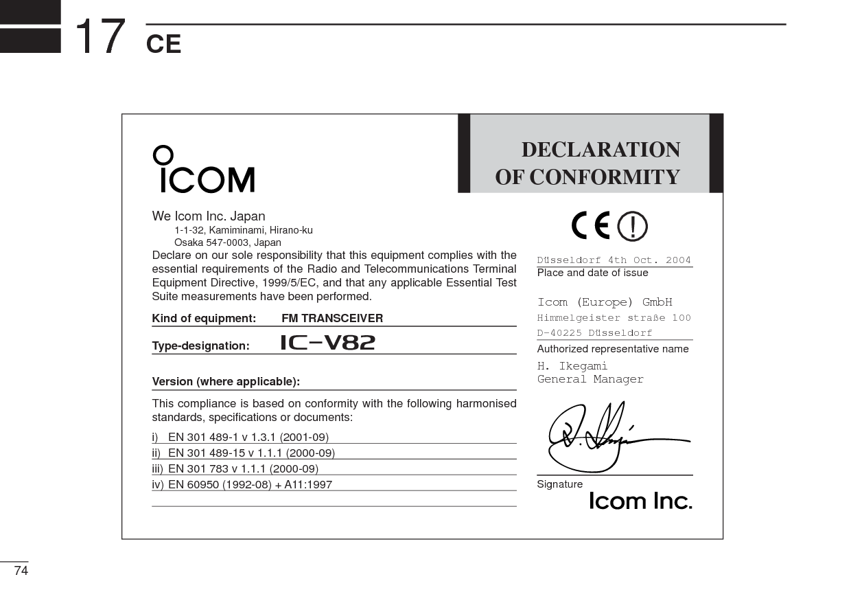
![339SUBAUDIBLE TONES9Separate tone frequencies can be set for tone squelch oper-ation rather than repeater operation (the same range of tonesis available— see right below). Like the repeater tones, theseare set in SET MODE.qSelect VFO or memory channel.wPush [A•FUNC], then push [8•SET]to enter SET MODE.ePush [YY]or [ZZ]several times until “Ct” appears when se-lecting CTCSS, or “dt” appears when selecting DTCS.•“ ” blinks when selecting CTCSS, or “ ” blinks when selectingDTCS.rRotate [VOL] to select the desired subaudible tone.tPush [✱•ENT](or [D•CLR]) to program the selected toneand exit SET MODE.When SET MODEis selected from memory mode.yPush [A•FUNC], then push [C•MR]for 1 sec. to transfer thecontents to VFO.•3 beeps are emitted. •VFO mode is selected automatically. uPush [A•FUNC], then push [C•MR]for 1 sec. •3 beeps are emitted.Steps yand uare necessary when overwriting the memorycontents permanently. The set tone frequency is used fortemporary operation only, therefore, these steps are not nec-essary. •Available CTCSS tone frequency list (unit: Hz)67.069.371.974.477.085.488.591.594.897.4100.0103.579.782.5107.2110.9114.8118.8123.0127.3131.8136.5141.3146.2151.4156.7159.8162.2165.5167.9171.3173.8177.3179.9183.5186.2189.9192.8196.6199.5203.5206.5210.7218.1225.7229.1233.6241.8250.3254.1DDSetting subaudible tones for tone squelch operation](https://usermanual.wiki/ICOM-orporated/282600.Users-Manual-Part-2/User-Guide-486360-Page-3.png)
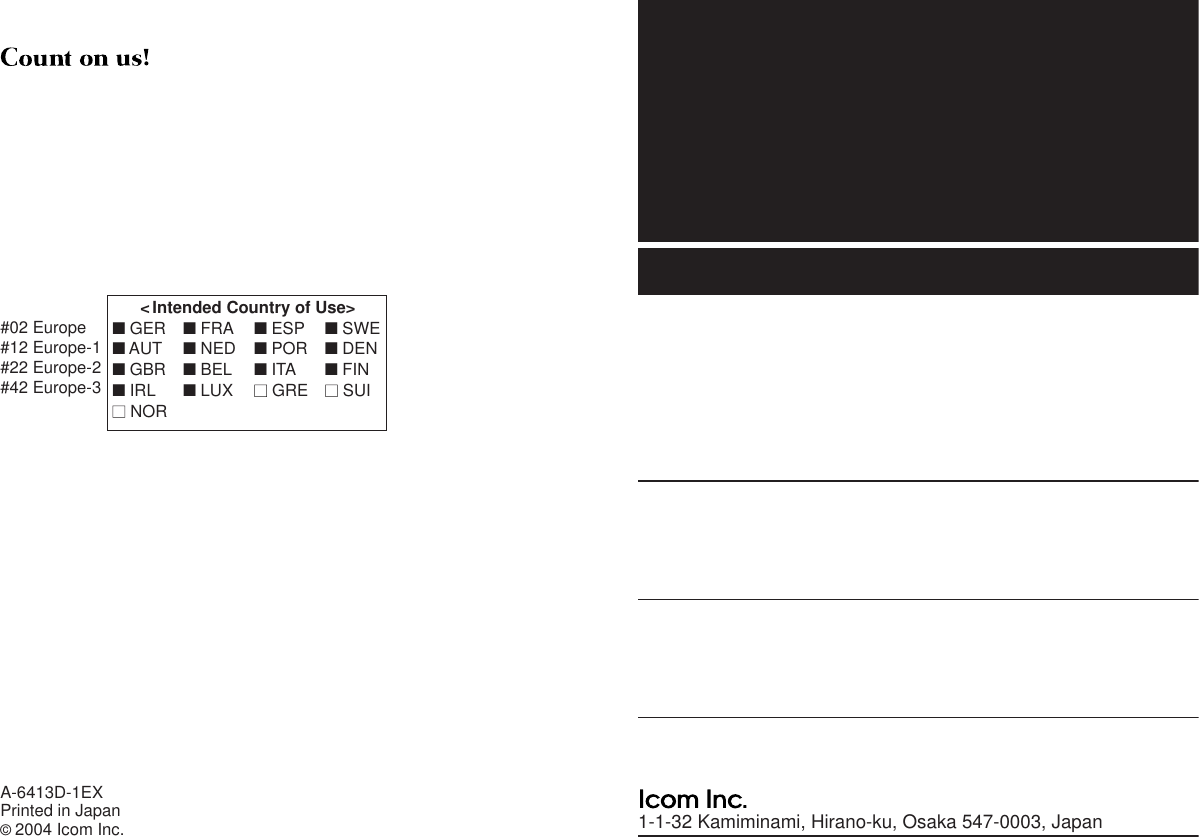
![349SUBAUDIBLE TONES■Pocket beep operationThis function uses subaudible tones for calling and can beused as a “common pager” to inform you that someone hascalled when you were away from the transceiver.DWaiting for a call from a specific stationqSet the operating frequency.wSet the desired CTCSS tone frequency or DTCS code inSET MODE.• See p. 33 for programming details.ePush [A•FUNC], then push [1•TONE].•Repeat several times until “ ” appears when CTCSS, or “ ” ap-pears when DTCS is selected.rPush [A•FUNC], then push [2•P.BEEP]to activate the pocketbeep function.•“” appears.tWhen a signal with the matched tone is received, thetransceiver emits beep tones and blinks “ .”• Beep tones sound for 30 sec. and “ ” blinks. To stop the beepsmanually, push any key. “ ” continues blinking until step yisoperated.yPush [PTT] to answer.• “ ” disappears and cancels the pocket beep function automati-cally. CTCSS DTCSPush FUNCAP.BEEP2CTCSS DTCSPush FUNCATONE1CTCSS DTCSD](https://usermanual.wiki/ICOM-orporated/282600.Users-Manual-Part-2/User-Guide-486360-Page-4.png)
![359SUBAUDIBLE TONES9■Tone scanBy monitoring a signal that is being operated with a repeater,pocket beep or tone squelch function, you can determine thetone frequency necessary to access a repeater or open thesquelch.qSet the frequency to be checked for a tone frequency orcode.wPush [A•FUNC], then push [1•TONE].•Repeat several times to select the tone condition or type to bescanned. (One of “ ,” “ ” or “ ” appears)•The tone scan can be operated even if the tone condition or typeis not selected.ePush [A•FUNC], then push [3•T.SCAN]to start the tonescan.• To change the scanning direction, push [YY]or [ZZ]. rWhen the CTCSS tone frequency or DTCS code ismatched, the squelch opens and the tone frequency orcode is temporarily programmed into the selected modesuch as memory or call channel.•The tone scan pauses when a CTCSS tone frequency or 3-digitDTCS code is detected.•The decoded CTCSS tone frequency or 3-digit DTCS code isused for the tone encoder or tone encoder/decoder dependingon the selected tone condition or type in step w.-No indication : Cannot be used for operation.-“ ” : CTCSS tone encoder-“ ” : CTCSS tone encoder/decoder-“ ” : DTCS tone encoder/decodertPush [D•CLR]to stop the scan.DPush FUNCAT.SCAN3Push FUNCATONE1D](https://usermanual.wiki/ICOM-orporated/282600.Users-Manual-Part-2/User-Guide-486360-Page-5.png)
![36PAGER/CODE SQUELCH10■Pager functionThis function uses DTMF codes for paging and can be usedas a “message pager” to confirm you of a caller’s identificationeven when you leave the transceiver temporarily unattended.■Code programmingDDBefore programmingThe pager and code squelch functions require ID codes and agroup code. These codes are 3-digit DTMF codes and mustbe written into the code channels before operation.qDecide the ID code of each transceiver and a group codefor your group.wDecide whether you want to return to normal operation orcode squelch operation after a connection is made.eProgram the ID code, group code and transmit codes(other station’s codes) as below.DDCode channel assignment*Channel CP automatically memorizes an ID code when receiving apager call. The contents in channel CP cannot be changed manually.Pager selective code (push [PTT])Beep BeepBeep Answer back (manual)Beep BeepBeep Set both transceivers to eithercode squelch or non-coded operationCommunicationID OR CODE CHANNEL “RECEIVE ACCEPT” OR GROUP CODE NUMBER “RECEIVE INHIBIT”Your ID code 0 “Receive accept” onlyOther parties’ 1–6 “Receive inhibit” should be ID codeprogrammed in each channel.Group code One of 1–6 “Receive accept” must be programmed.Memory space* P “Receive inhibit” only.Required Optional UT-108](https://usermanual.wiki/ICOM-orporated/282600.Users-Manual-Part-2/User-Guide-486360-Page-6.png)
![3710PAGER/CODE SQUELCH10DDCode programmingAn ID code MUST be programmed into code channel C0. Upto 6 transmit codes are programmable into code channels, C1to C6, if required.qPush [A•FUNC], then push [0•OPT]to enter OPTION SETMODE.•Rotate [VOL] to select “dtm.PG” or “dtm.CS,” if “dtm.OF” ap-pears.wPush [0•OPT]for 1 sec. to enter the code selection mode.•One of either “CP” or “C0” to “C6” blinks.•“C0” is the ID code and “C1” to “C6” are transmit codes.eRotate [VOL] (or push [YY]/[ZZ]) to select code channel C0.•Adifferent ID code must be programmed into each transceiver.rEnter the desired 3-digit ID code via the keypad.tRotate [VOL] (or push [YY]/[ZZ]) to select a transmit codechannel from C1 to C6. yEnter the desired 3-digit transmit code via the keypad.uPush [A•FUNC], then push [6•SKIP]to set the channel for“receive inhibit” or “receive accept.”•When “receive inhibit” is set, “SKIP” appears as below.•Code channel C0 cannot be set as “receive inhibit.”•See the table for “receive accept” and “receive inhibit” details(p. 36).iRepeat steps tand yto set additional transmit codechannels, if desired.oPush [✱•ENT]or [PTT] to exit CODE SET MODE.•Receive accept/receive inhibit➥“Receive accept” (“SKIP” indicator does not appear) ac-cepts pager calls when the transceiver receives a signalwith a code the same as that in the code channel.➥“Receive inhibit” (“SKIP” indicator appears) rejects callseven when the transceiver receives a code the same asthat in the code channel. Transmit codes should thereforebe programmed for “receive inhibit,” otherwise the trans-ceiver will not reject unnecessary calls.or](https://usermanual.wiki/ICOM-orporated/282600.Users-Manual-Part-2/User-Guide-486360-Page-7.png)
![3810 PAGER/CODE SQUELCH■Pager operationDCalling a specific stationqProgram the desired code channel in advance (p. 37).wSet the operating frequency.• Set the AF and squelch to the desired level as in normal opera-tion.ePush [A•FUNC], then push [0•OPT].•Rotate [VOL] to select “dtm.PG,” if “dtm.CS” or “dtm.OF” ap-pears.rSelect the desired transmit code channel:➥Push [0•OPT]for 1 sec. to enter the code selection con-dition.➥Rotate [VOL] to select the desired code channel.➥Push [✱•ENT]to return to previous condition.•100 MHz digit shows “P.” tPush [PTT] to transmit the pager code.yWait for an answer back.•When the transceiver receives an answer back code, the func-tion display shows the other member’s ID or group code.uAfter confirming a connection, push [A•FUNC] and [0•OPT]to enter OPTION SET MODE, then rotate [VOL] to select thecode squelch operation, or repeat the previous keyoperation again to select non-selective calling system.•DO NOT push any digit keys while code channels C0 to C6 aredisplayed, or code channel contents will be changed.iCommunicate with the other party as normal: push [PTT]to transmit; release to receive.DWaiting for a call from a specific stationqSet the operating frequency.wPush [A•FUNC], then push [0•OPT].➥Rotate [VOL] to select “dtm.PG,” if “dtm.CS” or“dtm.OF” appears.➥Push [✱•ENT]to return to previous condition.•100 MHz digit shows “P.” eWait for a call.•When receiving a call, the caller’s ID or group code appears asshown at next page.•DO NOT push any digit keys while code channels C0 to C6 aredisplayed, or code channel contents will be changed.rPush [PTT] to send an answer back call and display theoperating frequency.tAfter confirming a connection, push [A•FUNC] and [0•OPT]to enter OPTION SET MODE, then rotate [VOL] to select thecode squelch operation, or repeat the previous keyoperation again to select non-selective calling system.](https://usermanual.wiki/ICOM-orporated/282600.Users-Manual-Part-2/User-Guide-486360-Page-8.png)
![3910PAGER/CODE SQUELCH10•PERSONAL CALLSThis display appears when you are called with your ID codeand the calling station’s ID code is 123.•GROUP CALLSThis display appears when you are called with the groupcode, 888, and 888 has been programmed into code channelC6.•ERROR INFORMATIONWhen the transceiver receives an incomplete signal, “E” andpreviously received code appear.■Code squelchCode squelch provides communications with quiet standbysince you will only receive calls from stations which knowyour ID or group code. Each push of [PTT] sends a 3-digitcode in order to open the receiving station’s code squelchprior to voice transmission.qSet the operating frequency.• Set the AF and squelch to the desired level as in normal opera-tion.wPush [A•FUNC], then push [0•OPT].• Rotate [VOL] to select “dtm.CS,” if “dtm.PG” or “dtm.OF” ap-pears.eSelect the desired transmit code channel:➥Push [0•OPT]for 1 sec. to enter code selection condi-tion.➥Rotate [VOL] to select the desired code channel.➥Push [✱•ENT]to exit CODE SET MODEand return toprevious condition.•100 MHz digit shows “C.” rOperate the transceiver in the normal way (push [PTT] totransmit; release [PTT] to receive).tTo cancel the code squelch, push [A•FUNC]and [0•OPT],then rotate [VOL] to select “dtm.OF.”•100 MHz digit shows “1” when the function is cancelled.Previously received code.Code channel“CP” and “ ” blink.Pager/code squelch operation during channel indicationTo use these functions in channel indication, the pager/codesquelch setting must be programmed with other memory con-tents before selecting channel number indication.](https://usermanual.wiki/ICOM-orporated/282600.Users-Manual-Part-2/User-Guide-486360-Page-9.png)
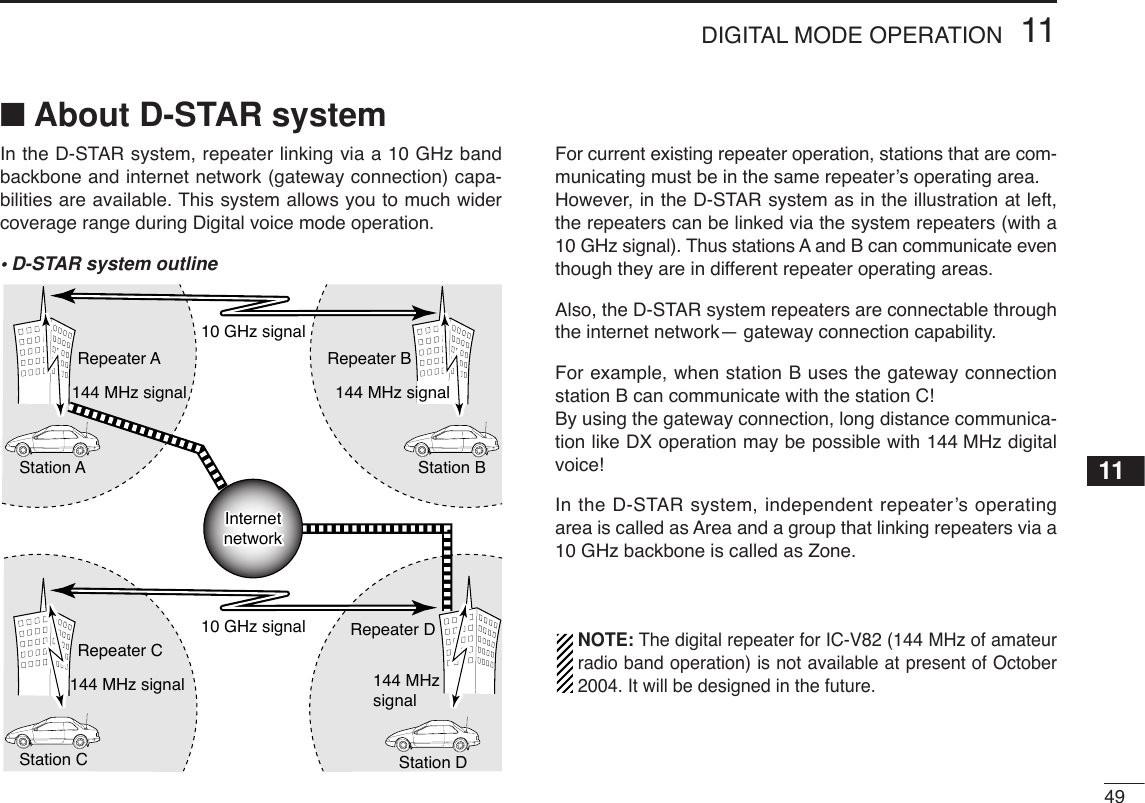
![■Digital mode operationThe IC-V82 with optional digital unit UT-118 can be operatedfor digital voice mode and low-speed data operation for bothtransmit and receive. Also available for connecting GPS re-ceiver (compatible with an RS-232C output/NMEA for-mat/4800 bps) and transmit/receive position data.■Call sign programmingFour kind of call sign memories are available for your own callsign “myC,” other station call sign “yUC” and nearest repeatercall sign “R1C” and another zone’s repeater call sign “R2C.”Each call sign memory can be stored up to 6 call signs, andeach call sign programmed up to 8 characters.DDYour call sign programmingYour call sign must be programmed for both Digital voice andlow-speed data communications (including GPS transmis-sion). qPush [A•FUNC]and [0•OPT]to enter OPTION SET MODE, thenpush [YY]or [ZZ]several times to select the call sign selectmode.•“myC” appears.wPush [0•OPT]for 1 sec. then rotate [VOL] to select the de-sired call sign channel.ePush [YY](or [ZZ]) to set into call sign programming condi-tion.•The 1st digit blinks and channel indication stops blinking.rRotate [VOL] to set the desired character or code.•Push [ZZ]or [YY]to move the cursor to left or right, respectively.tPush [YY](or [ZZ]) to select 2nd digit, then rotate [VOL] toset the desired character or code.•2nd digit blinks (1st digit stops blinking).•Repeat this step for programming your call sign.yPush [0•OPT]to fix the call sign.uRotate [VOL] to select an another channel from “C1” to“C6.”iRepeat steps wto uto program your call sign channels.40DIGITAL MODE OPERATION11 Required Optional UT-118](https://usermanual.wiki/ICOM-orporated/282600.Users-Manual-Part-2/User-Guide-486360-Page-10.png)
![4111DIGITAL MODE OPERATION11DDYour call sign note programmingYour call sign can be added some information such as oper-ating radio type, place or area. Call sign note can be storedup to 6 type, and each call sign note programmed up to 4characters.qPush [A•FUNC]and [0•OPT]to enter OPTION SET MODE, thenpush [YY]or [ZZ]several times to select the call sign selectmode.•“myS” appears.wPush [0•OPT]for 1 sec. then rotate [VOL] to select the de-sired call sign note channel.ePush [YY](or [ZZ]) to set into call sign note programmingcondition.•The 1st digit blinks and channel indication stops blinking.rRotate [VOL] to set the desired character or code.•Push [ZZ]or [YY]to move the cursor to left or right, respectively.tPush [YY](or [ZZ]) to select 2nd digit, then rotate [VOL] toset the desired character or code.•2nd digit blinks (1st digit stops blinking).•Repeat this step for programming your call sign note.yPush [0•OPT]to fix the call sign.uRotate [VOL] to select an another channel from “C1” to“C6.”iRepeat steps wto uto program your call sign channels.](https://usermanual.wiki/ICOM-orporated/282600.Users-Manual-Part-2/User-Guide-486360-Page-11.png)
![4211 DIGITAL MODE OPERATIONDDStation call sign programming Station call sign must be programmed for the specified sta-tion call as well as repeater operation in both Digital voice andlow-speed data communications.qPush [A•FUNC]and [0•OPT]to enter OPTION SET MODE, thenpush [YY]or [ZZ]several times to select the call sign selectmode.•“yUC” appears for station call sign.wPush [0•OPT]for 1 sec then rotate [VOL] to select the de-sired call sign channel.ePush [YY](or [ZZ]) to set into call sign programming condi-tion.•The 1st digit blinks and channel indication stops blinking.rRotate [VOL] to set the desired character or code.•Push [ZZ]or [YY]to move the cursor to left or right, respectively.tPush [YY](or [ZZ]) to select 2nd digit, then rotate [VOL] toset the desired character or code.•2nd digit blinks (1st digit stops blinking).•Repeat this step for programming station call sign.yPush [0•OPT]to fix the call sign.uRotate [VOL] to select an another channel from “C1” to“C6.”iRepeat steps wto uto program another station call signchannels.✔For your information:Station and/or repeater call sign can be programmed fromReceived call record when a call is received.See page 45 for details.](https://usermanual.wiki/ICOM-orporated/282600.Users-Manual-Part-2/User-Guide-486360-Page-12.png)
![4311DIGITAL MODE OPERATION11■Digital voice mode operationqSet the desired frequency in VFO mode. (pgs. 13, 14)•Select output power, if desired. (p. 15)wPush [A•FUNC]then [0•OPT]for enter OPTION SET MODE,then push [YY]or [ZZ]several times to select the digital se-lect mode.•“DG” appears.eRotate [VOL] to turn the digital mode ON.rPush [YY]once to select the your call sign select mode.•“myC” appears.tPush [0•OPT]for 1 sec. then rotate [VOL] to select the de-sired your call sign channel, if you have programmed sev-eral call signs.• After selecting the your call sign, push [0•OPT]to return to OP-TION SET MODE.DDWhen sending a CQ(continued from step t) ySelect “CQ” as the call sign.-Push [YY]or [ZZ]several times to select the call sign se-lect mode.•“yUC” appears.-Push [0•OPT]for 1 sec. then rotate [VOL] to select the de-sired channel.-Push [0•OPT]for 1 sec. to set “CqCqCq.”-Push [✱•ENT](or [D•CLR]) to exit OPTION SET MODE.uPush and hold [PTT] to transmit and speak into the micro-phone at normal voice level.•Transmit indicator appears and the RF meter shows the output power.iRelease [PTT] to return to receive.•The other station call sign will be received.•Received call signs can be stored into the received call recordautomatically. See page 44 for details.NOTE: In the digital mode operation; when “BUSY” indi-cator appears but no sound comes out the speaker, itmay be caused by the interference of FM mode. In thiscase, to prevent interference of FM mode, set the digitalmonitor setting (p. 47) to “An(analog)” then listen on thechannel before transmitting by pushing [MONI].Appears](https://usermanual.wiki/ICOM-orporated/282600.Users-Manual-Part-2/User-Guide-486360-Page-13.png)
![4411 DIGITAL MODE OPERATIONDDWhen calling the desired station(continued from p. 43 step t) ySelect the desired call sign.-Push [YY]or [ZZ]several times to select the call sign selectmode.•“yUC” appears.-Push [0•opt] then rotate [VOL] to select the desired callsign (pre-programmed), or set the desired call sign. (seep. 38)-Push [✱•ENT]to exit OPTION SET MODE.uPush and hold [PTT] to transmit and speak into the micro-phone at normal voice level.•Transmit indicator appears and the RF meter shows the output power.iRelease [PTT] to return to receive.•The other station call sign will be received.•Received call signs can be stored into the received call recordautomatically. See page 42 for details.■When receiving a Digital callWhen an individual station call is received, the calling stationcall sign can be stored into the received call record.The record is cleared once turning power OFF.DDReceived call recordqPush [A•FUNC]then [0•OPT]for enter OPTION SET MODE,then push [YY]or [ZZ]several times to select the receivedcall indication.•“RXCALL,” “R1CALL,” and “R2CALL” are available for the re-ceived station call sign, repeater 1/2 call signs, respectively.wTo confirm the received call, push [0•OPT]for 1 sec. toenter the received call sign indication mode.](https://usermanual.wiki/ICOM-orporated/282600.Users-Manual-Part-2/User-Guide-486360-Page-14.png)
![4511DIGITAL MODE OPERATION11DDTo store a received callqPush [A•FUNC]and [0•OPT]several times to select the callsign select mode.•“yUC” appears for station call sign.•“R1C” or “R2C” appears for repeater call sign.wPush [0•OPT]for 1 sec. to call sign indication, rotate [VOL]to select the blank channel or erasable channel.ePush [0•OPT]then, push [YY]or [ZZ]several times to selectthe received call indication.•“RXC.AL” appears for received station call sign.•“R1C.AL” or “R2C.AL” appears for received repeater call sign.rTo confirm the received call, push [0•OPT]for 1 sec. toenter the received call sign indication mode.tPush [0•OPT]for 1 sec. to store the call sign into the se-lected station call sign channel or repeater call sign chan-nel.■Break-in communicationThe break-in function allows you to break into an another sta-tions communications in both Digital voice and low-speeddata operation.qWhile receiving another station communication, push[A•FUNC]then [0•OPT]to enter OPTION SET MODE.wPush [YY]or [ZZ]several times to select the break-in set-ting, then turns the break-in setting ON.•“bRk” appears.eWhen both stations are in standby, transmit to send abreak-in call.•Programmed call sign station receives the break-in call as wellas your call sign.rWait for the reply call from the station who receive thebreak-in call.tAfter receive the reply call, communicate normal way.yTo cancel the break-in, push [A•FUNC]and [0•OPT], then ro-tate [VOL] to turn OFF.](https://usermanual.wiki/ICOM-orporated/282600.Users-Manual-Part-2/User-Guide-486360-Page-15.png)
![4611 DIGITAL MODE OPERATION■EMR communicationThe EMR communication mode is available for Digital modeoperation. In the EMR call, no call sign setting is necessary.qSet the desired frequency then push [A•FUNC]and [0•OPT]to enter OPTION SET MODE. wPush [YY]or [ZZ]several times to select the EMR setting,then turns the EMR setting ON.•“EmR” appears.eOperate the transceiver normal way.rTo cancel the EMR communication mode, push [A•FUNC]and [0•OPT]for 1 sec., then rotate [VOL] to turn OFF.■Pocket beep operationThis function uses a digital code/call sign for calling and canbe used as a “common pager” to inform you that someonehas called while you were away from the transceiver. The dig-ital code or call sign squelch does not function while in a low-speed data communication.DDWaiting for a call from a specific stationqSet the operating frequency.wProgram the digital code or call sign in setting mode.•See p. 51, “Digital code setting” or p. 40 “Call sign program-ming.”ePush [A•FUNC]and [1•TONE]one or more times until “ ”or “ ” appears in the function display.•“ ” for call sign squelch; “ ” for digital code squelch operation.rPush [A•FUNC], then push [2•P.BEEP]to activate the pocketbeep function.•“ ” appears.tWhen a signal with the matched call sign/digital code is re-ceived, the transceiver emits beep tones and blinks “ .”• Beep tones sound for 30 sec. and “ ” blinks. To stop the beeps man-ually, push any key. “ ” continues blinking until step yis operated.yPush [PTT] to answer.• “ ” disappears and cancels the pocket beep function automati-cally. uTo cancel the call sign/digital code squelch, push [A•FUNC]and [1•TONE]one or more times until or “ ” or “ ” disap-pears.](https://usermanual.wiki/ICOM-orporated/282600.Users-Manual-Part-2/User-Guide-486360-Page-16.png)
![4711DIGITAL MODE OPERATION11■Digital squelch functionsThe digital code (CSQL) or call sign (DSQL) squelch opensonly when receiving a voice signal with the same pre-pro-grammed digital code or call sign, respectively. The digitalcode or call sign squelch does not function while in a low-speed data communication.qSet the operating frequency.wProgram the digital code or call sign in setting mode.•See p. 51, “Digital code setting” or p. 40 “Call sign program-ming.”ePush [1•TONE]one or more times until “ ” or “ ” appearsin the function display.•“ ” for call sign squelch; “ ” for digital code squelch operation.rWhen a signal with the matched call sign/digital code is re-ceived, the squelch opens and the signal can be heard.•When the received signal includes an unmatched call sign/digitalcode, the squelch does not open. However, the S-meter showsthe received signal strength.•To open the squelch manually, push and hold [MONI].tOperate the transceiver in the normal way (push [PTT] totransmit; release [PTT] to receive).yTo cancel the call sign/digital code squelch, push [1•TONE]one or more times until or “ ” or “ ” disappears.■Digital monitorThis function is used to listen to the analog signal (FM modesignal) without changing the operating mode while digital (DVmode) operation.qWhile pushing [YY]and [ZZ], turn the power ON to enter INI-TIAL SET MODE.wPush [YY]or [ZZ]several times until “dmO” appears.eRotate [VOL] to turn the repeater lockout function to “RP,”“bU” or OFF.•“An”: Activate for monitoring the analog (FM mode) signals.(default)•“dG”: Activate to open the call sign or digital code squelch.rPush [✱•ENT](or [D•CLR]) to exit INITIAL SET MODE.NOTE: When “digital monitor setting” is set to “An (ana-log),” the monitor function (pushing [MONI]) works as theanalog monitor for receiving an FM signal. Then digitalmonitor function is activate using the Squelch control(pushing [MONI] and [YY]or [ZZ]).USINGINITIAL SET MODE✔While scanning in digital mode:• The call sign squelch function deactivate, then after can-celling the scan it will activate again.• Scan stops near channel in a 5 kHz tuning steps, and thenno sound comes out.](https://usermanual.wiki/ICOM-orporated/282600.Users-Manual-Part-2/User-Guide-486360-Page-17.png)
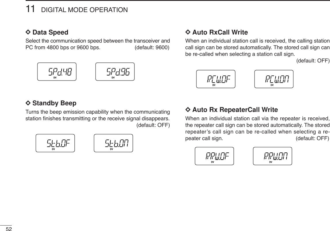
![4811 DIGITAL MODE OPERATION■Low-speed data communicationIn addition to the digital voice communication, a low-speeddata communication is available (Refer p. 4 about the trans-ceiver-PC connection details).qSet the desired frequency.wSet another settings, such as repeater call, transmit outputpower.ePush [A•FUNC]then [0•OPT]for enter OPTION SET MODE,then push [YY]or [ZZ]several times to select the automaticdata transmission setting. (see p. 51)•“AtX” appears.•Skip this setting, if you want to transmit manually.rPush [YY]once to select the data communication speedsetting. (see p. 52)•“SPd” appears.•Select suitable data speed for your PC or application.tStart up the low-speed data communication application.ySet the application as follows.•Port : The same COM port number as IC-V82’s•Baud rate : 4800 bps or 9600 bps (same as step r)•Data : 8 bit•Parity : None•Stop : 1 bit•Flow control : Xon/XoffuTransceiver automatically transmits or receives the datawhile you sending data to transceiver. Or push and hold[PTT] to transmit, release to receive the data manually.•Refer to the instruction of the application that how to send or re-ceive data.](https://usermanual.wiki/ICOM-orporated/282600.Users-Manual-Part-2/User-Guide-486360-Page-18.png)
![5011 DIGITAL MODE OPERATION■Repeater call sign programmingRepeater call sign must be programmed for the repeater op-eration in both Digital voice and low speed data communica-tions.qPush [A•FUNC] and [0•OPT]to enter OPTION SET MODE, thenpush [YY]or [ZZ]several times to select the call sign items.•“R1C” or “R2C” appears for repeater call sign.wPush [0•OPT]for 1 sec. then rotate [VOL] to select the de-sired call sign channel.ePush [YY](or [ZZ]) to set into call sign programming condi-tion.•The 1st digit blinks and channel indication stops blinking.rRotate [VOL] to set the desired character or code.•Push [ZZ]or [YY]to move the cursor to left or right, respectively.tPush [YY](or [ZZ]) to select 2nd digit, then rotate [VOL] toset the desired character or code.•2nd digit blinks (1st digit stop blinking).•Repeat this step for programming repeater call sign.yPush [0•OPT]to fix the call sign.uRotate [VOL] to select an another channel from “C1” to“C6.”iRepeat steps wto uto program another repeater callsign channels.✔For your information:Station and/or repeater call sign can be programmed fromReceived call record when a call is received.See page 45 for details.✔For your information:Repeater call sign can be programmed gateway connectioncapabilities at step rfor connecting to the other Area orZone.•“G” appears or disappears at the 8th digit when each pushing[8•SET].](https://usermanual.wiki/ICOM-orporated/282600.Users-Manual-Part-2/User-Guide-486360-Page-20.png)
![5111DIGITAL MODE OPERATION11j3■Other setting itemsqPush [A•FUNC]and [0•OPT]to enter OPTION SET MODE, thenpush [YY]or [ZZ]several times to select the desired item.wRotate [VOL] to select the desired value or condition.DDAuto ReplyDuring Digital mode operation, auto reply function is avail-able. This function replies to an individual station call evenyou are away from the transceiver. (default: OFF)After the manual transmission (pushing [PTT]) or messagetransmission, the Auto Reply setting is return to OFF auto-matically. DDDigital CodeSets the desired digital code for digital code squelch opera-tion. Total of 100 codes (00–99) are available. (default: 00)DDAuto data TransmissionDuring low-speed data operation, auto data transmissionfunction is available. This function transmits when data areinput from PC via the [DATA] jack. (default: OFF)After the manual transmission (pushing [PTT]), the AutoTransmission setting is return to OFF automatically.](https://usermanual.wiki/ICOM-orporated/282600.Users-Manual-Part-2/User-Guide-486360-Page-21.png)
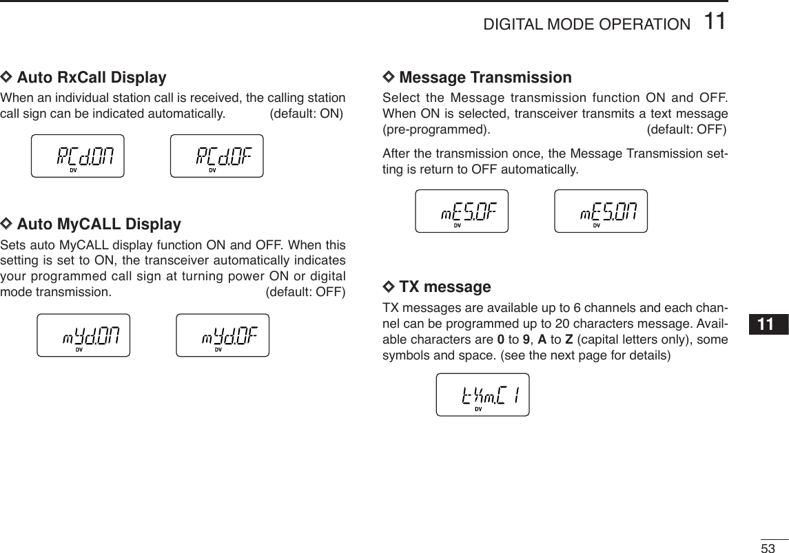
 to select “tXm,”then push [0•OPT]for 1 sec. to edit the message indicationthen rotate [VOL] to select the message channel.•One of either “C1” to “C6” blinks.wPush [YY]to set into message programming condition.•The 1st digit blinks and channel indication stops blinking.eRotate [VOL] to set the desired character.rPush [YY]to select 2nd digit, then rotate [VOL] to set thedesired character.•2nd digit blinks (1st digit stop blinking).•Repeat this step for programming.tPush [0•OPT]to set the message.yRepeat steps wto tto set another message channels.uPush [✱•ENT](or [D•CLR])to exit OPTION SET MODE.• Available characters(3)(D)(N)(X)(+) (4)(E)(O)(Y)(–)(”)(5)(F)(P)(Z)(✱)(6)(G)(Q)(/)(7)(H)(R)(,)(8)(I)(S)(space)(9)(T)(0)(A)(U)(1)(B)(V)(2)(C) (J) (K)(L)(M)(W)(.)( ))(( )(’)(&)(%)($)(#)(!)(<)(:) (;) (=) (>) (?)(@)([) (\) (]) (^)](https://usermanual.wiki/ICOM-orporated/282600.Users-Manual-Part-2/User-Guide-486360-Page-24.png)
![5511DIGITAL MODE OPERATION11■GPS operationThe IC-V82 can indicate the current position (Latitude and Longi-tude) when a GPS receiver (compatible with an RS-232C out-put/NMEA format/4800 bps) is connected to [DATA] jack. Andalso can transmit the position data and message to other stations.DDPosition indicationqWhile connecting a GPS receiver, push [A•FUNC]and[0•OPT]to enter OPTION SET MODE.wPush [YY]or [ZZ]several times to select the GPS setting.•“GPS” appears.eRotate [VOL] to set the suitable sentence formatter for theconnecting GPS receiver.•For your position indication is necessary to select “GGA” or “RMC.”•Sentence formatters rPush [YY]twice to select the position indication.tPush [0•OPT]for 1 sec. to enter the position indication.•Latitude and longitude date appear in order as below.yAfter checking the current position, push [✱•ENT](or[D•CLR]) to return to normal operating mode.IMPORTANT: When set the sentence formatter at step efor connecting GPS receiver, and already programmed yourcall sign, GPS automatic transmission is activate every 3minutes. The automatic transmission can be changed inter-val time or deactivated, if desired. (see the next page)DegreesNorth or South Minutes SecondsPushPushDegreesEast or WestMinutesSeconds12345GLLGGARMCGSAVTG678910GLL, GGAGLL, RMCGLL, GSAGLL, VTGGGA, RMC1112131415GGA, GSAGGA, VTGRMC, GSARMC, VTGGSA, VTG1617181920GLL, GGA, RMCGLL, GGA, GSAGLL, GGA, VTGGLL, RMC, GSAGLL, RMC, VTG2122232425GLL, GSA, VTGGGA, RMC, GSAGGA, RMC, VTGGGA, GSA, VTGRMC, GSA, VTG](https://usermanual.wiki/ICOM-orporated/282600.Users-Manual-Part-2/User-Guide-486360-Page-25.png)
![5611 DIGITAL MODE OPERATIONDDGPS Automatic transmissionqWhile connecting a GPS receiver, push [A•FUNC]and[0•OPT]to enter OPTION SET MODE.wPush [YY]or [ZZ]several times to select the GPS automatictransmission.•“GtX” appears.eRotate [VOL] to set the interval time for the GPS auto-matic transmission.•Interval time is selectable from 0.5 (30 sec.), 1, 3, 5, 10, 30 min.rPush [YY]three times to select the transmit message se-lection, if desired. •GPS TX message is selectable from OFF and C1 to C6.•TX message must be programmed in advance. (see page 50 forsetting)tPush [✱•ENT](or [D•CLR]) to exit OPTION SET MODE.IMPORTANT: GPS Automatic transmission transmits atevery setting interval even while receiving an another sta-tions communication. To prevent interfere the another sta-tions, set the GPS transmission together with the Repeaterlockout item “RLO” (set to “bU” busy lockout) in INITIAL SETMODE. (p. 62)DDReceiving a GPS transmissionqPush [A•FUNC]and [0•OPT]to enter OPTION SET MODE.wPush [YY]or [ZZ]several times to select the received posi-tion.•“RXP.OS” appears.ePush [0•OPT]for 1 sec. to enter the position indication.•Latitude data and longitude date appear by every pushing [YY]or [ZZ].rPush [0•OPT]then push [YY]twice to select the receivedGPS message.tPush [0• OPT]for 1 sec. to enter the message.•Received message is indicated, push [ZZ]or [YY]to move thecursor to left or right, respectively.yAfter checking a received position and message, push[✱•ENT](or [D•CLR]) to return to normal operating mode.](https://usermanual.wiki/ICOM-orporated/282600.Users-Manual-Part-2/User-Guide-486360-Page-26.png)
![5712OTHER FUNCTIONS1112■SET MODEDDEntering SET MODEqPush [A•FUNC], then push [8•SET]to enter SET MODE.wPush [YY]or [ZZ]to select the desired item.eRotate [VOL] to select the condition/value.•To exit SET MODE, push [✱•ENT](or [D•CLR]).DDRepeater tone frequencySelects tone encoder frequency for accessing a repeater, etc.from one of 50 available frequencies.•67.0–254.1 Hz (50 tones): 88.5 Hz (default)DDTone squelch frequencySelects frequency for tone squelch or pocket beep operationfrom one of 50 available frequencies.•67.0–254.1 Hz (50 tones): 88.5 Hz (default)•Available subaudible tone frequencies 67.069.371.974.477.079.782.585.488.591.594.897.4100.0103.5107.2110.9114.8118.8123.0127.3131.8136.5141.3146.2151.4156.7159.8162.2165.5167.9171.3173.8177.3179.9183.5186.2189.9192.8196.6199.5203.5206.5210.7218.1225.7229.1233.6241.8250.3254.1FUNCASET8ENT[VOL]Enter ExitSet](https://usermanual.wiki/ICOM-orporated/282600.Users-Manual-Part-2/User-Guide-486360-Page-27.png)
![5812 OTHER FUNCTIONSDDDTCS code Selects DTCS (both encoder/decoder code) for DTCSsquelch operation. Total of 104 codes are available.•023–754: 023 (default)DDDTCS polarity Selects DTCS polarities for transmission and reception from“NN,” “NR,” “RN” and “RR.” (N: normal/R: reverse)DDTuning step Selects tuning step from 5 (default), 10, 12.5, 15, 20, 25 , 30and 50 kHz for [YY]/[ZZ]or [VOL] (When [VOL] is assigned astuning dial) operation.DDOffset frequencySets the duplex offset frequency within 0 to 20 MHz range.During duplex (repeater) operation, transmit frequency (or re-ceive when reverse function is set to ON) shifts the set fre-quency. (default value may differ depending on versions)DDReverse functionTurns the reverse function ON and OFF (default).Reverse function OFF (default)Reverse function ON](https://usermanual.wiki/ICOM-orporated/282600.Users-Manual-Part-2/User-Guide-486360-Page-28.png)
![5912OTHER FUNCTIONS12DDScan pause timerSelects the scan pause time from SCt.5, SCt.10, SCt.15 andSCP. 2. When receiving signals, the scan pauses accordingto the scan pause time.•SCt. 5/10/15 : Scan pauses for 5/10/15 sec. (default: SCt.15)•SCP. 2 : Scan pauses until the signal disappears. Re-sumes 2 sec. after the signal disappears.DDFunction key timerSelects [A•FUNC]effect timer from F0.At, F1.At, F2.At, F3.Atand F .m.•F0.At : “ ” disappears immediately after secondary func-tion is operated. (default)•F1/2/3.At: “ ” disappears after 1/2/3 sec. after secondaryfunction is operated. •F .m : “ ” appears until [A•FUNC]is pushed again.DDLCD backlightSelects LCD backlight lighting condition from auto, ON andOFF.•LIG.At : Lights when any key except [PTT] is pushed.(default)•LIG.ON : Lights continuously while the transceiver is pow-ered ON.•LIG.OF : Never lights.DDTransmission permissionTurns transmission permission ON and OFF. This functioncan be set for each memory and call channel, independently.•tX .ON : Transmission is permitted. (default)•tX .OF : Transmission is inhibited.FFF](https://usermanual.wiki/ICOM-orporated/282600.Users-Manual-Part-2/User-Guide-486360-Page-29.png)
![6012 OTHER FUNCTIONSDDMemory bank settingSets the desired memory bank (A to J and OFF) to assign theregular memory channels.This item appears when SET MODEis accessed from memorymode only.DDMemory bank link functionSets the memory bank link function ON and OFF (default).The link function provides continuous banks scan, that scansall contents in the selected banks during bank scan.This item appears when SET MODEis accessed from memorymode only.•Bank link settingqRotate [VOL] to select the memory bank link function ON.wPush [YY]or [ZZ]to select the desired bank to be linked.•BLA: Bank A, BLB: Bank B, BLC: Bank C, BLD: Bank D, BLE: Bank E, BLF: Bank F, BLG: Bank G, BLH: Bank H, BLI: Bank I, BLJ: Bank JeRotate [VOL] to select “ON” to linking the bank.rRepeat steps wand eto set the link condition.DDWide/Narrow settingSelects both the transmission and reception passband widthfrom wide (default) and narrow.When narrow is selected, the transmission and receptionpassband width become half of the wide setting (approx.).This setting can be set for each memory, call and VFO inde-pendently.DDWeather alert functionTurns weather alert function ON and OFF (default).USA version only](https://usermanual.wiki/ICOM-orporated/282600.Users-Manual-Part-2/User-Guide-486360-Page-30.png)
![6112OTHER FUNCTIONS12■INITIAL SET MODEThe INITIAL SET MODEis accessed at power on and allows youto set seldom-changed settings. In this way, you can “cus-tomize” transceiver operations to suit your preference and op-erating style. DDEntering INITIAL SET MODEqWhile pushing [YY]and [ZZ], turn power ON. wPush [YY]or [ZZ]to select the desired item.eRotate [VOL] to select the condition or value.•To exit INITIAL SET MODE, push [✱•ENT](or [D•CLR]).DDKey-touch beepTurns key-touch beep emission ON (Beep level 1 to 3) andOFF. (default: 3)DDTime-out timerTo prevent accidental prolonged transmission, etc., the trans-ceiver has a time-out timer. This function cuts a transmissionOFF after 1–30 min. of continuous transmission. This timercan be cancelled.•tOt.OF : The time-out timer is turned OFF. (default)•tOt. 1–30: The transmission is cut OFF after the set periodelapses.[VOL]ENTPWREnter ExitSetATPOWER ON](https://usermanual.wiki/ICOM-orporated/282600.Users-Manual-Part-2/User-Guide-486360-Page-31.png)
![6312OTHER FUNCTIONS12DDDTMF speedThe rate at which DTMF memories send individual DTMFcharacters can be set to accommodate operating needs.•1: 100 msec. interval; 5.0 cps speed (default)•2: 200 msec. interval; 2.5 cps speed •3: 300 msec. interval; 1.6 cps speed •5: 500 msec. interval; 1.0 cps speed (cps=characters/sec.)DDDial assignmentSelects [VOL] control action from AF volume and tuning dial.•tOP.VO: AF volume (default)•tOP.dI : Tuning dial DDDisplay typeSelects LCD indication type from frequency, channel numberand channel names.•dSP.FR : Shows frequency (default)•dSP.CH : Shows channel number*•dSP.Nm : Shows channel names*Memory channels only can be selected.DDLCD contrastSelects LCD contrast from auto, high and low.•LCd.AT : Automatic (default)•LCd.HI : High contrast •LCd.LO : Low contrast](https://usermanual.wiki/ICOM-orporated/282600.Users-Manual-Part-2/User-Guide-486360-Page-33.png)
![6412 OTHER FUNCTIONSDDPower saveSelects duty cycle for power save function from auto, 1:32,1:16, 1:8, 1:2 and OFF.•P–S.At : Duty cycle changes automatically. (default)•P–S.32 : 1:32 duty cycle •P–S.16 : 1:16 duty cycle•P–S. 8 : 1:8 duty cycle•P–S. 2 : 1:2 duty cycle•P–S.OF : The power save function is turned OFF.NOTE: While DV mode operation (with UT-118), or pager/CSQL operation (with UT-108), the active duty cycle is fixed1:1 only (even any duty cycle setting other than OFF).DDMonitor key actionThe monitor key, [MONI], can be set as a ‘sticky’ key. Whenset to the sticky condition, each push of [MONI] toggles themonitor function ON and OFF.•PU (Push) : Pushing and holding [MONI] to monitorthe frequency. (default)•HO (Hold) : Push [MONI] to monitor the frequencyand push again to cancel it.DDTuning speed accelerationThe tuning speed acceleration automatically speeds up thetuning speed when pushing and holding [YY]or [ZZ], or rotat-ing [VOL] rapidly.*• S–S.At : The tuning speed acceleration is activated. (de-fault)•S–S. m: The tuning speed acceleration is not activated. *When tuning dial is assigned with [VOL].](https://usermanual.wiki/ICOM-orporated/282600.Users-Manual-Part-2/User-Guide-486360-Page-34.png)
![6512OTHER FUNCTIONS12DDMic simple modeThis item turns the microphone simple mode ON and OFF.Microphone simple mode is used to change the function as-signments for keys in the optional HM-75AREMOTE CONTROLSPEAKER-MICROPHONEas below. This assignment is conve-nient for 3-channel use of simple operation.•mIC.n1 : Normal 1 (default)•mIC.n2 : Normal 2•mIC.Sm: Simple modeA1750 Hz tone can be transmitted with the HM-75A opera-tion. ➥Push [A] while pushing [PTT]. NOTE:Turn power OFF when connecting the HM-75A to thetransceiver.VFO mode cannot be selected via the microphone whenSIMPLE mode is selected.DDS-meter squelchSets S-meter squelch threshold level from OFF and S1–S3.This setting allows you to set a minimum signal level needs toopen the squelch.DDALC functionSets the ALC (automatic Level Control) function ON and OFF(default).The ALC function reduces the microphone gain automaticallywhen the transmission audio is distorted.Optional HM-75A requiredHM-75A Mode NORMAL1 NORMAL2 SIMPLEkey[A] Freq. [B•CALL][MONI] [MONI]CH Null[B] Freq. VFO/Memory VFO/Memory [B•CALL]CH Null Null[YY]Freq. Freq. Up Freq. Up MR-00CHCH Memory CH Up Memory CH Up[ZZ]Freq. Freq. Down Freq. Down MR-01CHCH Memory CH Down Memory CH Down](https://usermanual.wiki/ICOM-orporated/282600.Users-Manual-Part-2/User-Guide-486360-Page-35.png)
![6612 OTHER FUNCTIONSDDBattery protection functionSets the Battery protection function for LI (Li-Ion) and OFF(default).LI(Li-Ion):➥The transceiver is required pushing [PWR] for tuningpower ON with every battery detach and attach.➥Beep sounds when the attached battery is exhaustion.•The battery must be charged presently.OFF : The transceiver memorizes the transceiver ON/OFFcondition at battery is detached.NOTE: This item MUST be set “LI” (Li-Ion) when the at-taching battery is BP-211N (Li-Ion).■Weather channel operation(USA version only)DDWeather channel selectionqPush [C•MR]several times to select weather channel group.wPush [YY]or [ZZ]several times to select the desiredweather channel. ePush [C•MR]to select memory mode, or push [D•CLR]toselect VFO mode.DDWeather alert functionNOAA broadcast stations transmit weather alert tones beforeimportant weather announcements. When the weather alertfunction is turned ON, the selected weather channel is moni-tored each 5 sec. for the announcement. When the alert sig-nal is detected, the “ALt” and the WX channel are displayedalternately and sounds a beep tone until the transceiver is op-erated. The previously selected (used) weather channel ischecked periodically during standby or while scanning.Weather channel group indication](https://usermanual.wiki/ICOM-orporated/282600.Users-Manual-Part-2/User-Guide-486360-Page-36.png)
![6712OTHER FUNCTIONS12qSelect the desired weather channel.wTurn the weather alert function ON in set mode.➥Push [A•FUNC]and [8•SET]to enter SET MODE.➥Push [YY]or [ZZ]to select the weather alert item, thenrotate [VOL] to set ON.➥push [✱•ENT](or [D•CLR]) to exit SET MODE.eSets the desired stand-by condition.•Selects VFO, memory or call channel.•Scan or priority watch operation can also be selected.rWhen the alert is detected, a beep sounds and the follow-ing indication will be displayed.tTurn the weather alert function OFF in SET MODE.☞NOTE: While receiving a signal (on a frequency other thanthe weather alert ON frequency), the receiving signal oraudio will be interrupted momentarily every 5 sec. (approx.)in case the alert function is turned ON. This symptom iscaused by the WX alert function. To cancel these symp-toms, set the weather alert item OFF in SET MODE.■CPU resetThe function display may occasionallydisplay erroneous information (e.g. whenfirst applying power). This may becaused externally by static electricity orother factors.If this problem occurs, turn power OFF.After waiting a few seconds, turn powerON again. If the problem persists, per-form CPU resetting operation as follows.• While pushing [MONI] and [D•CLR],turn power ON.CAUTION:Resetting the CPU returns the radio to factory default settings. ■Partial resetIf you want to initialize the operatingconditions (VFO frequency, VFO set-tings, set mode contents) withoutclearing the memory contents, a par-tial resetting function is available forthe transceiver.• While pushing [D•CLR], turn thepower ON to partially reset thetransceiver.ATPOWER ONATPOWER ONShows above indications alternately.PWRMONICLRDPWRCLRD](https://usermanual.wiki/ICOM-orporated/282600.Users-Manual-Part-2/User-Guide-486360-Page-37.png)
![Cloning allows you to quickly and easily transfer the pro-grammed contents from one transceiver to another trans-ceiver.DTransceiver-to-transceiver cloningqConnect the OPC-474 CLONING CABLEto the [SP] jack ofthe master and sub-transceivers. •The master transceiver is used to send data to the sub-trans-ceiver.wWhile pushing [A•FUNC]and [YY],turn power ON to enter cloningmode (master transceiver only—power ON only for sub-transceiver).•“CLONE” appears and the transceiversenter the clone standby condition.ePush [PTT] on the master transceiver.•“CL OU” appears in the master transceiver’s display and S-meterindicator shows that data is being transferred to the sub-trans-ceiver.•“CL IN” appears automatically in the sub-transceiver’s displayand S-meter indicator shows that data is being received from themaster transceiver.rWhen cloning is finished, turn power OFF, then ON againto exit cloning mode.DCloning using a PCPlease refer to the HELP file that comes with CS-V82CLONING SOFTWARE.NOTE: DO NOT push the [PTT] on the sub-transceiverduring cloning. This will cause a cloning error.PCTRANSCEIVERto USB portto RS-232C portOPC-478 (RS-232C type)OPC-478U (USB type)PWRFUNCAATPOWER ON68CLONING13](https://usermanual.wiki/ICOM-orporated/282600.Users-Manual-Part-2/User-Guide-486360-Page-38.png)
![7115SPECIFICATIONS1415GENERAL•Frequency coverage : (unit: MHz)USA Tx: 144–148/Rx: 136–174*Europe, Taiwan, Korea Tx/Rx: 144–146General (LM), CSA (LM) Tx/Rx: 136–174**Guaranteed: 144–148 MHz range only.•Type of emission : FM•Number of memory channels : 207 (incl. 6 scan edges and 1 call)•Frequency resolution : 5, 10, 12.5, 15, 20, 25, 30, 50 kHz•Operating temperature range : –10°C to +60°C; +14˚F to +140˚F•Frequency stability : ±2.5 ppm (–10°C to +60°C)•Power supply requirement : 7.2 V DC (6–10.3 V DC acceptable;Icom’s battery pack only)•Current drain (at 7.2 V DC: approx.): Transmit at 7 W (High) 2.6 Aat 4 W (Middle) 2.0 Aat 0.5 W (Low) 1.0 AReceive standby 80 mApower save 30 mAmax. audio 250 mA•Antenna connector : BNC (50 Ω)•Dimensions (proj. not included) :54(W) ×139(H) ×36.7(D) mm21⁄8(W)×515⁄32(H)×17⁄16(D) in•Weight (approx.) : 390 g; 13.8 oz (with BP-222N and Ant.)200 g; 7.1 oz (without battery pack and Ant.)TRANSMITTER•Modulation system : Variable reactance frequency mod.•Output power (at 7.2 V) : 7 W/4W/0.5W (High/Mid/Low)•Max. frequency deviation : ±5.0 kHz [Wide]/±2.5 kHz [Narrow]•Spurious emissions : Less than –60 dBc•Microphone connector : 3-conductor 2.5 (d) mm (1⁄8″)/2.2 kΩRECEIVER•Receive system : Double-conversion superheterodyne•Intermediate frequencies : 1st: 46.35 MHz, 2nd: 450 kHz•Sensitivity (at 12 dB SINAD) :0.16 µV typical•Squelch sensitivity (threshold) :0.11 µV typical•Selectivity :[Wide] More than 55 dB[Narrow] More than 50 dB•Spurious and image rejection : 80 dB typical•Intermodulation : 65 dB typical•AF output power (at 7.2 V DC):More than 0.3 W at 10% distortion withan 8 Ωload•Ext. speaker connector : 3-conductor 3.5 (d) mm (1⁄8″)/8 Ω•Ext. Data connector : 3-conductor 2.5 (d) mm (1⁄8″)](https://usermanual.wiki/ICOM-orporated/282600.Users-Manual-Part-2/User-Guide-486360-Page-41.png)