ICOM orporated 259000 Amateur HF Scanning Transceiver User Manual IC 7800 Eng
ICOM Incorporated Amateur HF Scanning Transceiver IC 7800 Eng
Contents
- 1. Users Manual Part 1
- 2. Users Manual Part 2
- 3. Users Manual Part 3
- 4. Users Manual Part 4
- 5. Users Manual Part 5
Users Manual Part 3
![5-2■Spectrum scope screenThis function allows you to display the conditions of theselected band, as well as relative strengths of signals.The IC-7800 has two modes for the spectrum indica-tion— one is center mode, and anther one is fix mode. In addition, the IC-7800 has a mini scope screen forregular scope indication.DCenter modeDisplays signals around the set frequency within theselected span. The set frequency is always displayedat the center of the screen.qPush [EXIT/SET] several times to close a multi-function screen, if necessary.wPush [F-1•SCOPE] to select the scope screen.ePush [F-5•CENT/FIX] to select the center mode.• “ ” is displayed when center mode is selected.rPush [F-1•SPAN] several times to select the scopespan.• ±2.5, ±5.0, ±10, ±25, ±50, ±100 and ±250 kHz are avail-able.• Sweeping speed is selectable for each span indepen-dently in scope set mode. (pgs. 5-5, 5-6)tPush [F-2•ATT] several times to activate an attenu-ator or turn the attenuator OFF.• 10, 20 and 30 dB attenuators are available.yPush [F-6•MAIN/SUB] to select main band.• The spectrum scope with sub band selection is activatedduring dualwatch or split frequency operation only.uPush [F-3•MARKER] several times to select themarker (sub readout or transmit frequency) or turnthe marker OFF.• “ ” displays the marker at the transmit frequency.• “ ” displays the marker at the sub readout frequency.• “<<” or “>>” appears when the marker is out of range.• The spectrum scope shows the transmit signal wave-form while transmitting. This can be deactivated inscope set mode. (p. 5-4)• The spectrum scope shows the peak level holding func-tion. Peak levels are displayed in the background of thecurrent spectrum in a different color until the receive fre-quency changes. This can be deactivated and the wave-form color can be set in scope set mode. (p. 5-5)iPush [F-4•HOLD] to freeze the current spectrumwaveform.• “ ” appears while the function is in use.• The peak hold function can be deactivated in scope setmode.oPush [EXIT/SET] to exit the scope screen.NOTE: If a strong signal is received, a ghost wave-form may appear. Push [F-2•ATT] several times toactivate the spectrum scope attenuator in this case.Spurious signal waveform may be displayed. Theyare made in internal scope circuit and does not indi-cate a transceiver malfunction.HOLD[F-3•MARKER][F-2•ATT][F-1•SPAN] [EXIT/SET][F-5•CENT/FIX][F-4•HOLD][F-6•MAIN/SUB]5FUNCTIONS FOR RECEIVE• Observed indication example](https://usermanual.wiki/ICOM-orporated/259000.Users-Manual-Part-3/User-Guide-397409-Page-2.png)
![5-3DFix modeDisplays signals within the specified frequency range.The selected frequency band conditions can begrasped at a glance when using this mode.qPush [EXIT/SET] several times to close a multi-function screen, if necessary.wPush [F-1•SCOPE] to select the scope screen.ePush [F-5•CENT/FIX] to select the fix mode.• “ ” is displayed when fix mode is selected.rPush [F-2•ATT] several times to activate an attenu-ator or turn the attenuator OFF.• 10, 20 and 30 dB attenuators are available.tPush [F-6•MAIN/SUB] to select main band.• The spectrum scope with sub band selection is activatedduring dualwatch or split frequency operation only.yPush [F-3•MARKER] several times to select themarker (sub readout or transmit frequency) or turnthe marker OFF.• “ ” displays the marker at the main readout frequency.(always displayed)• “ ” displays the marker at the transmit frequency.• “ ” displays the marker at the sub readout frequency.• “<<” or “>>” appears when the marker is out of range.• The spectrum scope shows the transmit signal wave-form while transmitting. This can be deactivated inscope set mode. (p. 5-4)• The spectrum scope shows the peak level holding func-tion. Peak levels are displayed in the background of thecurrent spectrum in a different color until the receive fre-quency changes. This can be deactivated and the wave-form color can be set in scope set mode. (p. 5-5)uPush [F-4•HOLD] to freeze the current spectrumwaveform.• “ ” appears while the function is in use.• The peak hold function can be deactivated in scope setmode.iPush [EXIT/SET] to exit the scope screen.NOTE: If a strong signal is received, a ghost wave-form may appear. Push [F-2•ATT] several times toactivate the spectrum scope attenuator in this case.The scope band width can be specified for each op-erating frequency band independently in scope setmode. (pgs. 5-6 to 5-8)HOLD[F-3•MARKER][F-2•ATT][EXIT/SET][F-5•CENT/FIX][F-4•HOLD][F-6•MAIN/SUB]5FUNCTIONS FOR RECEIVE](https://usermanual.wiki/ICOM-orporated/259000.Users-Manual-Part-3/User-Guide-397409-Page-3.png)
![5-4DMini scope screen indicationThe mini scope screen can be displayed with anotherscreen indication, such as set mode menu, decoderscreen, memory list screen, etc. simultaneously.qSet the scope mode (center or fix), marker, attenu-ator, span, etc. in advance. (pgs. 5-2, 5-3)wPush [M.SCOPE] to toggle the mini scope indica-tion ON and OFF.• The S/RF meter type during mini scope indication canbe selected in display set mode (Meter Type (WideScreen) item). (p. 12-11)DScope set modeThis set mode is used to set the waveform color,sweeping speed, scope range for fix mode, etc.qDuring spectrum scope indication ON, push [F-7•SET] to select scope set mode screen.• Push [F-7•WIDE] to toggle the screen size between nor-mal and wide.wPush [F-1•Y] or [F-2•Z] to select the desired setitem.eSet the desired condition using the main dial.• Push [F-4•DEF] for 1 sec. to select the default conditionor value.• Push [F-3•Ω≈] to select the set contents for someitems.rPush [EXIT/SET] to exit from set mode.[F-1•Y] Main dial[EXIT/SET][F-2•Z][F-4•DEF][F-3•Ω ≈] [F-7•WIDE][M.SCOPE]5FUNCTIONS FOR RECEIVETurn the transmitting signal waveform indication ONand OFF. NOTE: The transmitting signal waveform indica-tion is available for the center mode only.](https://usermanual.wiki/ICOM-orporated/259000.Users-Manual-Part-3/User-Guide-397409-Page-4.png)
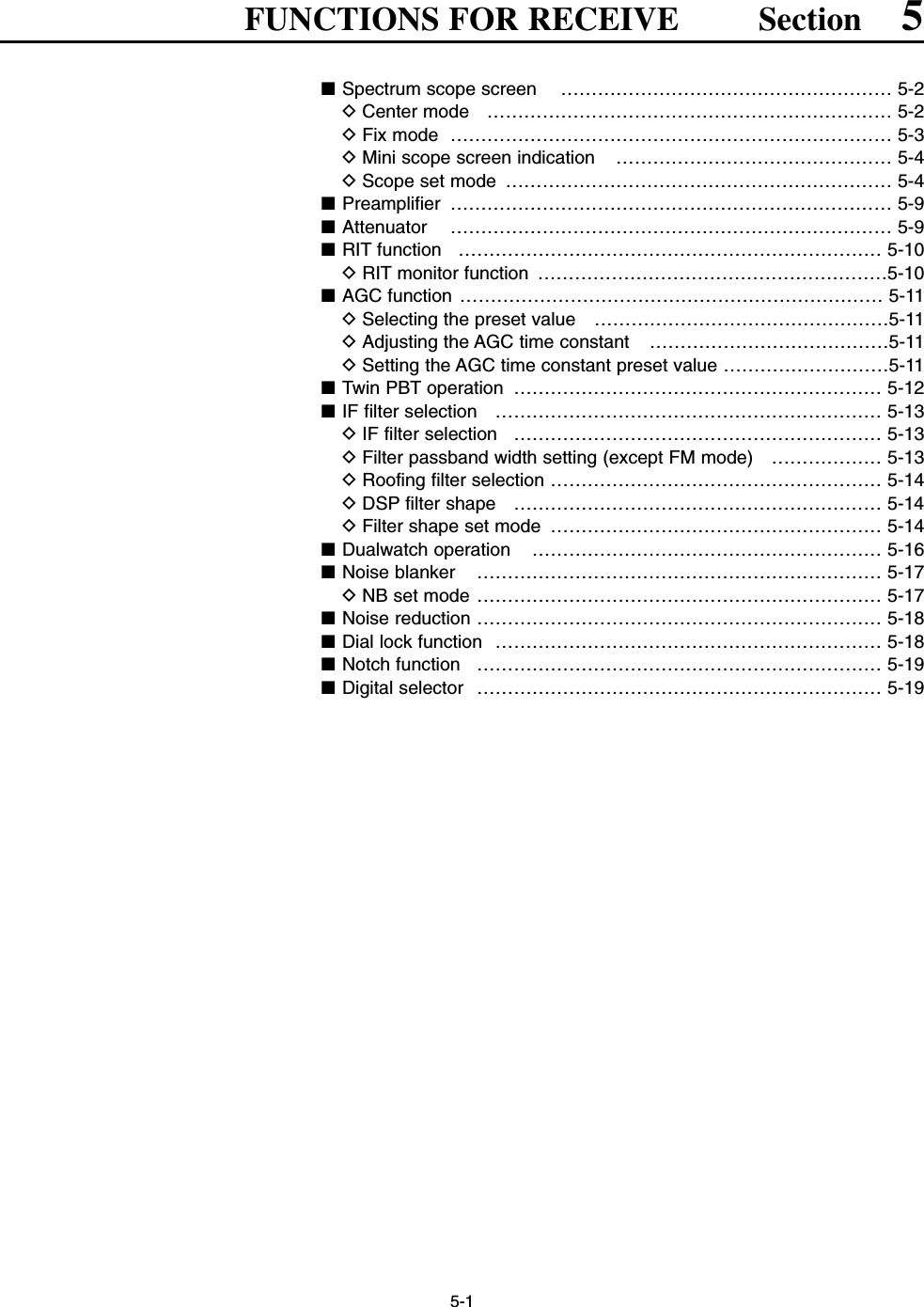
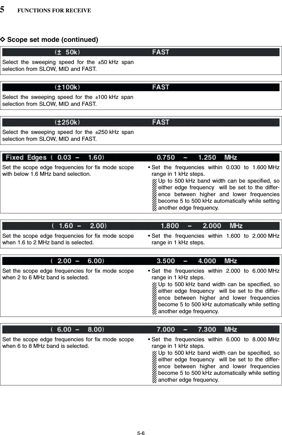
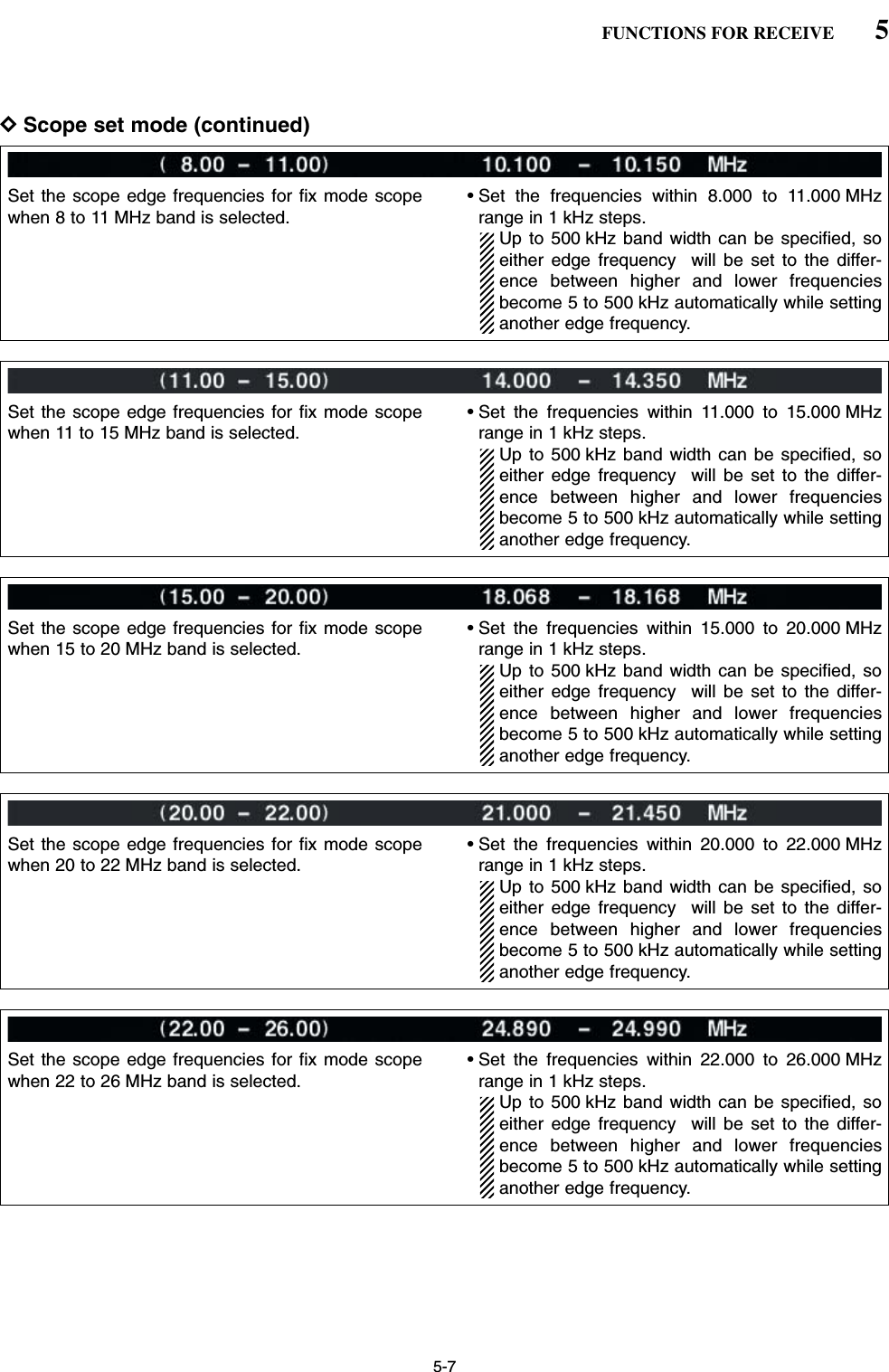
![5-5DScope set mode (continued)5FUNCTIONS FOR RECEIVETurn the peak level holding function ON and OFF. Select the center frequency of the spectrum scopeindication (center mode only).• Filter center : Shows the selected filter’s centerfrequency at the center.• Carrier Point Center: Shows the selected operatingmode carrier point frequency atthe center.• Carrier Point Center (Abs. Freq.): In addition to the carrier pointcenter setting above, the actualfrequency is displayed for thebottom of the scope.Set the waveform color for the currently receiving sig-nals.• The color is set in RGB format.• Push [F-3•Ω≈] to select R (Red), G (Green) and B(Blue), and rotate the ratio from 0 to 255 range.• The set color is indicated in the box beside the RGBscale.Set the waveform color for the receiving signals max-imum level.• The color is set in RGB format.• Push [F-3•Ω≈] to select R (Red), G (Green) and B(Blue), and rotate the ratio from 0 to 255 range.• The set color is indicated in the box beside the RGBscale.Select the sweeping speed for the ±2.5 kHz spanselection from SLOW, MID and FAST.NOTE: The waveform may be displayed incorrect-ly with “FAST” setting.Select the sweeping speed for the ±5 kHz spanselection from SLOW, MID and FAST.NOTE: The waveform may be displayed incorrect-ly with “FAST” setting.Select the sweeping speed for the ±10 kHz spanselection from SLOW, MID and FAST.Select the sweeping speed for the ±25 kHz spanselection from SLOW, MID and FAST.](https://usermanual.wiki/ICOM-orporated/259000.Users-Manual-Part-3/User-Guide-397409-Page-5.png)
![5-9■PreamplifierThe preamp amplifies received signals in the front endcircuit to improve the S/N ratio and sensitivity. Set thisto preamp 1 or preamp 2 when receiving weak signals. ➥Push [P.AMP] several times to set the preamp OFF,preamp 1 ON or preamp 2 ON.For all HF bandsHigh gain preamp for 24 MHz band andabove✔About the “P.AMP2”The “P.AMP 2” is a high gain receive amplifier. Whenthe “P.AMP 2” is used during times of strong electricfields, distortion sometimes results. In such cases, usethe transceiver with the “P.AMP 1” or “P.AMP OFF” set-ting.The “P.AMP 2” is most effective when:• Used on bands above 24 MHz and when electricfields are weak.• Receive sensitivity is insufficient during low gain, orwhile using a narrow band antenna (such as smallloop, a Beverage antenna or a short Yagi antenna,etc.) is used.■AttenuatorThe attenuator prevents a desired signal from distor-tion when very strong signals are near the desired fre-quency or when very strong electric fields, such asfrom broadcasting stations, are near your location.➥Push [ATT] several times to set the attenuator 6 dB,12 dB, 18 dB or attenuator OFF.➥Push [ATT] for 1 sec. several times to set the atten-uator 3 dB, 6 dB, 9 dB, 12 dB, 15 dB, 18 dB, 21 dBor attenuator OFF.[ATT][P.AMP]5FUNCTIONS FOR RECEIVE3dBattenuation6dBattenuation9dBattenuation12 dBattenuation15 dBattenuation18 dBattenuation21 dBattenuation](https://usermanual.wiki/ICOM-orporated/259000.Users-Manual-Part-3/User-Guide-397409-Page-9.png)
![5-10■RIT functionThe RIT (Receive Increment Tuning) function com-pensates for off-frequencies of the communicatingstation.The function shifts the receive frequency up to±9.99 kHz in 10 Hz steps without moving the transmitfrequency.qPush [RIT] to turn the RIT function ON and OFF.• “ ” and the shifting frequency appear when the func-tion is ON.wRotate the [RIT/∂TX] control.• Push [CLEAR] for 1 sec. to reset the RIT frequency.• Push [CLEAR] momentarily to reset the RIT frequencywhen the quick RIT/∂TX clear function is ON. (p. 12-17)• Push [RIT] for 1 sec. to add the shift frequency to the op-erating frequency.DRIT monitor functionWhen the RIT function is ON, pushing and holding[XFC] allows you to monitor the operating frequencydirectly (RIT is temporarily cancelled).✔For your convenience— Calculate functionThe shift frequency of the RIT function can beadded/subtracted to the displayed frequency.➥While displaying the RIT shift frequency, push [RIT]for 1 sec.[XFC][RIT][RIT/∂TX][CLEAR]5FUNCTIONS FOR RECEIVE](https://usermanual.wiki/ICOM-orporated/259000.Users-Manual-Part-3/User-Guide-397409-Page-10.png)
![5-11■AGC functionThe AGC (auto gain control) controls receiver gain toproduce a constant audio output level even when thereceived signal strength is varied by fading, etc.The transceiver has 3 AGC characteristics (time con-stant; fast, mid, slow) for non-FM mode. The FM mode AGC time constant is fixed as ‘FAST’(0.1 sec.) and AGC time constant cannot be se-lected.DSelecting the preset valueqSelect non-FM mode.wPush [AGC] several times to select AGC fast, AGCmedium (MID) or AGC slow.DAdjusting the AGC time constant qSelect non-FM mode.wPush [AGC VR], then rotate [AGC] control to adjustthe AGC time constant.• [AGC VR] indicator above the switch lights green.DSetting the AGC time constant preset valueqSelect the desired mode except FM mode.wPush [AGC] for 1 sec. to enter AGC set mode.ePush [AGC] several times to select FAST time con-stant.rRotate the main dial to set the desired time constantfor ‘AGC FAST.’• AGC time constant can be set between 0.1 to 8.0 sec.(depends on mode) or turned OFF.• Push [F-4•DEF] for 1 sec. to select a default value.tPush [AGC] to select medium time constant.yRotate the main dial to set the desired time constantfor ‘AGC MID.’• AGC time constant can be set between 0.1 to 8.0 sec.(depends on mode) or turned OFF.• Push [F-4•DEF] for 1 sec. to select a default value.uPush [AGC] to select slow time constant.iRotate the main dial to set the desired time constantfor ‘AGC SLOW.’• AGC time constant can be set between 0.1 to 8.0 sec.(depends on mode) or turned OFF.• Push [F-4•DEF] for 1 sec. to select a default value.oSelect another mode except FM. Repeat steps etoiif desired.!0 Push [EXIT/SET] to exit the AGC set mode screen.[AGC][AGC] control for main[AGC VR] for main [AGC VR] for sub[AGC] control for sub5FUNCTIONS FOR RECEIVEMode Default Selectable AGC time constant0.3 (FAST) 0.1, 0.2, 0.3, 0.5, 0.8, 1.2, 1.6, 2.0, SSB 2.0 (MID) 2.5, 3.0, 4.0, 5.0, 6.06.0 (SLOW)0.1 (FAST) 0.1, 0.2, 0.3, 0.5, 0.8, 1.2, 1.6, 2.0, CW 0.5 (MID) 2.5, 3.0, 4.0, 5.0, 6.01.2 (SLOW)RTTY 0.1 (FAST) 0.1, 0.2, 0.3, 0.5, 0.8, 1.2, 1.6, 2.0, PSK 0.5 (MID) 2.5, 3.0, 4.0, 5.0, 6.01.2 (SLOW)3.0 (FAST) 0.3, 0.5, 0.8, 1.2, 1.6, 2.0, 2.5, 3.0, AM 5.0 (MID) 4.0, 5.0, 6.0, 7.0, 8.07.0 (SLOW)FM 0.1 (FAST) Fixed• Selectable AGC time constant (unit: sec.)](https://usermanual.wiki/ICOM-orporated/259000.Users-Manual-Part-3/User-Guide-397409-Page-11.png)
![5-12■Twin PBT operationGeneral PBT (Passband Tuning) function electronicallynarrows the IF passband width by shifting the IF fre-quency to slightly outside of the IF filter passband toreject interference. This transceiver uses the DSP cir-cuit for the PBT function. Moving both [TWIN PBT]controls to the same position shifts the IF.➥The LCD shows the passband width and shift fre-quency graphically.➥Push [FILTER] for 1 sec. to enter the filter setscreen. Current passband width and shift frequencyis displayed in the filter set screen.➥To set the [TWIN PBT] controls to the center posi-tions, push [PBT CLR] for 1 sec.The variable range depends on the passband widthand mode. The edge of the variable range is half of thepassband width, and PBT is adjustable in 25 or 50 Hzsteps.• [TWIN PBT] should normally be set to the center posi-tions (PBT setting is cleared) when there is no interfer-ence.• When PBT is used, the audio tone may be changed.• Not available for FM mode.• While rotating [TWIN PBT], noise may occur. This comesfrom the DSP unit and does not indicate an equipmentmalfunction.• PBT operation exampleIF center frequency Interference Desired signalPassbandBoth controls at center positionCutting a lower passbandCutting both higher and lower passbandsInterference InterferenceDesired signalPassbandPBT1PBT2PBT1PBT2PBT1PBT2Shows filter width, shifting value and condition[TWIN PBT] for main[PBT CLEAR] for main [PBT CLEAR] for sub[TWIN PBT] for sub5FUNCTIONS FOR RECEIVE](https://usermanual.wiki/ICOM-orporated/259000.Users-Manual-Part-3/User-Guide-397409-Page-12.png)
![5-13■IF filter selectionThe transceiver has 3 passband width IF filters foreach mode. For SSB, CW and PSK modes, the passband widthcan be set within 50 to 3600 Hz in 50 or 100 Hz steps.A total of 41 passband widths are available. For RTTY mode, the passband width can be set within50 to 2700 Hz in 50 or 100 Hz steps. A total of 32 pass-band widths are available.For AM mode, the passband width can be set within200 Hz to 10 kHz in 200 Hz steps. A total of 50 pass-band widths are available.For FM mode, the passband width is fixed and 3 pass-band widths are available.The filter selection is automatically memorized ineach mode.The PBT shift frequencies are automatically memo-rized in each filter.DIF filter selectionqSelect the desired mode.wPush [FILTER] several times to select the IF filter 1,2 or 3.• The selected passband width and filter number is dis-played in the LCD.DFilter passband width setting (except FM mode)qPush [FILTER] for 1 sec. to enter filter set screen.wSelect any mode except FM.• Passband widths for FM modes are fixed and cannot beset.ePush [FILTER] several times to select the desired IFfilter.rWhile pushing [F-1•BW], rotate the main dial to setthe desired passband width.• In SSB, CW and PSK modes, the passband width canbe set within the following range.50 to 500 Hz 50 Hz steps600 to 3600 Hz 100 Hz steps• In RTTY mode, the passband width can be set within thefollowing range.50 to 500 Hz 50 Hz steps600 to 2700 Hz 100 Hz steps• In AM mode, the passband width can be set within thefollowing range.200 Hz to 10 kHz 200 Hz steps• Push [F-4•DEF] for 1 sec. to select the default value.tRepeat steps wto rif desired.yPush [EXIT/SET] to exit filter set screen.The PBT shift frequencies are cleared when thepassband width is changed.This filter set screen graphically displays the PBTshift frequencies and CW pitch operations.[FILTER] for main [FILTER] for sub5FUNCTIONS FOR RECEIVE](https://usermanual.wiki/ICOM-orporated/259000.Users-Manual-Part-3/User-Guide-397409-Page-13.png)
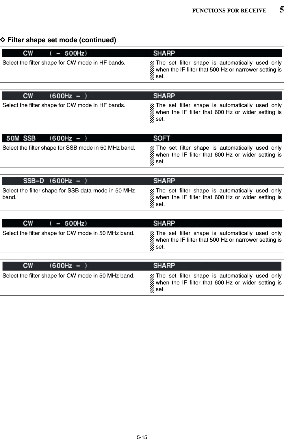
![5-14DRoofing filter selectionThe IC-7800 has 6 kHz roofing filter. The roofing filterallows you an interference reduction from nearbystrong signals.qPush [FILTER] for 1 sec. to enter filter set screen.wSelect any mode except FM.ePush [F-6•ROOFING] to select the desired filterfrom 15 kHz (regular 1st IF filter) and 6 kHz (roofing fil-ter).• Push [F-4•DEF] for 1 sec. to select a default value.rPush [EXIT•SET] to exit filter set screen.DDSP filter shape The type of DSP filter shape for each SSB, SSB dataand CW can be selected independently from soft andsharp.qPush [FILTER] for 1 sec. to enter filter set screen.wSelect SSB, SSB data or CW mode.ePush [F-7•SHAPE] to select the desired filter shapefrom soft and sharp.rPush [EXIT•SET] to exit filter set screen.The filter shape can be set for each band (HF and50 MHz bands), mode, as well as the passband widthsetting (CW only) independently as your default settingin filter shape set mode.DFilter shape set modeThe type of DSP filter shape for each SSB, SSB dataand CW can be selected independently from soft andsharp.qPush [FILTER] for 1 sec. to enter filter set screen.wPush [F-7•SHAPE] for 1 sec. to enter filter shape setmode.ePush [F-1•Y] or [F-2•Z] to select the desired item.rRotate the main dial to select the filter shape fromsoft and sharp.tPush [EXIT/SET] to exit filter shape set mode.5FUNCTIONS FOR RECEIVESelect the filter shape for SSB mode in HF bands. The set filter shape is automatically used onlywhen the IF filter that 600 Hz or wider setting isset.Select the filter shape for SSB data mode in HFbands.The set filter shape is automatically used onlywhen the IF filter that 600 Hz or wider setting isset.](https://usermanual.wiki/ICOM-orporated/259000.Users-Manual-Part-3/User-Guide-397409-Page-14.png)
![5-16■Dualwatch operationDualwatch monitors 2 frequencies simultaneously. The IC-7800 has 2 independent receiver circuits toallow you to a dualwatch even in different frequencyband and mode. qSet the desired frequency and mode into the mainband.wPush [DUALWATCH].• “ ” appears.• Pushing [DUALWATCH] for 1 sec., the sub band isequalized at the same time. This quick dualwatch func-tion can be turned OFF in set mode. (p. 12-13)eRotate the sub dial to set the desired frequency.rPush [SUB] to enables the sub band access whenchanging the frequency band, operating mode, etc.in sub band. • Push [MAIN] for the main band access.tRotate [AF] for sub band to adjust the sub bandaudio level.yTo transmit on the sub band readout, push[CHANGE] or [SPLIT].NOTE:•Beat may be sound according to the set frequen-cy combination, such as 3.5 MHz and 7 MHzband’s frequencies.• Receiver sensitivity will be decreased when thesame frequency band and the same antenna areselected during dualwatch.• The RIT function can be used for the main read-out only.• The ∂TX function can be used for the transmitreadout (main readout when the split functionOFF; sub readout when the split function ON).[MAIN][DUALWATCH][CHANGE] Sub dial[AF] for sub[SPLIT][SUB]5FUNCTIONS FOR RECEIVE• Split frequency operation during dualwatch](https://usermanual.wiki/ICOM-orporated/259000.Users-Manual-Part-3/User-Guide-397409-Page-16.png)
![5-17■Noise blankerThe noise blanker eliminates pulse-type noise such asfrom car ignitions. The noise blanker is not availablefor FM mode.qPush [NB] to turn the noise blanker function ON andOFF.• [NB] indicator above their switch lights green.wRotate [NB] control to adjust the noise blankerthreshold level.When using the noise blanker, received signals maybe distorted if they are excessively strong or thenoise type is different. Turn the noise blanker OFF,or rotate [NB] control to a shallow position in suchcase.DNB set modeTo deal with various type of noises, attenuation leveland noise width can be set in NB set mode.qPush [NB] for 1 sec. to enter NB set mode.wPush [F-1•Y] or [F-2•Z] to select the desired item.eRotate the main dial to set the desired level or value. • Push [F-4•DEF] for 1 sec. to select a default value.rPush [EXIT/SET] to exit filter shape set mode.[NB] for main[NB] control for sub[NB] control for main[NB] for sub5FUNCTIONS FOR RECEIVESet the noise attenuation level within 1 to 10.Set the noise pulse width within 1 to 100.](https://usermanual.wiki/ICOM-orporated/259000.Users-Manual-Part-3/User-Guide-397409-Page-17.png)
![5-18■Noise reductionThe noise reduction function reduces noise compo-nents and picks out desired signals which are buriedin noise. The received signals are converted to digitalsignals and then the desired signals are separatedfrom the noise.qPush the [NR] to turn the noise reduction ON.• [NR] indicator above their switch lights green.wRotate the [NR] control to adjust the noise reductionlevel.ePush the [NR] switch to turn the noise reductionOFF.• [NR] indicator lights off.Deep rotation of the [NR] control results in audiosignal masking or distortion. Set the [NR] control formaximum readability.■Dial lock functionThe dial lock function prevents changes by accidentalmovement of the main dial. The lock function electron-ically locks the dial.➥Push [LOCK] to toggle the dial lock function ON andOFF.• The [LOCK] indicator lights when the dial lock functionis in use.[LOCK] indicator for main[LOCK] for sub[LOCK] for main[LOCK] indicator for sub[NR] for main[NR] control for sub[NR] control for main[NR] for sub5FUNCTIONS FOR RECEIVE](https://usermanual.wiki/ICOM-orporated/259000.Users-Manual-Part-3/User-Guide-397409-Page-18.png)
![5-19■Notch functionThis transceiver has auto and manual notch functions. The auto notch function automatically attenuates morethan 3 beat tones, tuning signals, etc., even if they aremoving. The manual notch can be set to attenuate afrequency via the [NOTCH] control.The auto notch can be used in SSB, AM and FMmodes.The manual notch can be used in SSB, CW, RTTY,PSK and AM modes.• Auto notch indication➥Push [NOTCH] to toggle the notch function betweenauto, manual and OFF in SSB and AM modes.➥Push [NOTCH] to turn the manual notch functionON and OFF in CW mode.➥Push [NOTCH] to turn the auto notch function ONand OFF in FM mode.• [NOTCH] indicator above their switch lights green.• Push [NOTCH] for 1 sec. to select the notch filter widthfor manual notch from wide, middle and narrow.• Set to attenuate a frequency for manual notch via the[NOTCH] control.• “ ” appears when auto notch is in use.• “ ” appears when manual notch is in use.While operating the manual notch, noise may beheard. This comes from the DSP unit and does notindicate an equipment malfunction.■Digital selectorThe digital selector manually adjusts the center fre-quency of the automatic pre-selector.The automatic pre-selector filters the desired signalonly and eliminates intermodulation from anotherbands strong signals at the RF stage. The automatic pre-selector that operates in conjunc-tion with the operating frequency, follows the changein operating frequency at the minimum kHz steps.qPush [DIGI-SEL] to turn the digital selector ON andOFF.• [DIGI-SEL] indicator above their switch lights green.wRotate [DIGI-SEL] control to adjust the center fre-quency.NOTE:• When rotating the main dial (and sub dial during thedualwatch or split function) while the digital selectoris activated, mechanical noise will be heard due tothe switching noise from internal relays. • The preamp (P.AMP1 or P.AMP2) cannot be usedwhile the digital selector is activated.[DIGI-SEL] control for main[DIGI-SEL] for sub[DIGI-SEL] for main[DIGI-SEL] control for sub[NOTCH] control for main[NOTCH] for sub[NOTCH] for main[NOTCH] control for sub5FUNCTIONS FOR RECEIVE• Manual notch indication](https://usermanual.wiki/ICOM-orporated/259000.Users-Manual-Part-3/User-Guide-397409-Page-19.png)
![6-2■VOX functionThe VOX (Voice-Operated Transmission) functionswitches between transmit and receive with your voice.This function provides an opportunity to input log en-tries into your computer, etc., while operating.DUsing the VOX functionqSelect a phone mode (SSB, AM, FM).wPush [VOX/BK-IN] to turn the VOX function ON orOFF.• “VOX” appears while the VOX is in use.• [VOX/BK-IN] indicator above this switch lights green.DAdjusting the VOX functionqSelect a phone mode (SSB, AM, FM).wPush [VOX/BK-IN] to turn VOX function ON.eWhile speaking into the microphone with your nor-mal voice level, rotate [VOX GAIN] to the pointwhere the transceiver is continuously transmitting.rDuring receive, rotate [ANTI VOX] to the pointwhere the transceiver does not switching to transmitwith the receive audio from the speaker.tAdjust the VOX delay and the VOX voice delay inVOX set mode, if necessary.DVOX set modeqPush [VOX/BK-IN] for 1 sec. to enter VOX setmode.wSelect the VOX gain item using [F-1•Y] or [F-2•Z].eRotate the main dial to the desired set value or con-dition.• Push [F-4•DEF] for 1 sec. to select a default value.rPush [EXIT/SET] to exit VOX set mode.[VOX/BK-IN][ANTI VOX][VOX GAIN][AM/FM][SSB][VOX/BK-IN][AM/FM][SSB]6FUNCTIONS FOR TRANSMITSet the VOX delay for a convenient interval before re-turning to receive within 0 to 2.0 sec. range.Set the VOX voice delay to prevent mis-transmissionof your voice when switching to transmit.Short, Mid., Long and OFF settings are available.When using the VOX voice delay, turn the TX mon-itor function OFF. The transmission audio will beechoed.](https://usermanual.wiki/ICOM-orporated/259000.Users-Manual-Part-3/User-Guide-397409-Page-21.png)
![6-3■Break-in functionThe break-in function is used in CW mode to automat-ically toggle the transceiver between transmit and re-ceive when keying. The IC-7800 is capable for fullbreak-in or semi break-in.DSemi break-in operationDuring semi break-in operation, the transceiver selectstransmit when keying, then automatically returns to re-ceive after a pre-set time from when you stop keying.qPush [CW] to select CW or CW-R mode.wPush [VOX/BK-IN] several times to turn the semibreak-in function ON.• “BK IN” appears.eRotate [DELAY] to set the break-in delay time (thedelay from transmit to receive).When using a paddle, rotate [KEY SPEED] to adjustthe keying speed.DFull break-in operationDuring full break-in operation, the transceiver auto-matically selects transmit while keying and returns toreceive immediately after keying is finished.qPush [CW] to select CW or CW-R mode.wPush [VOX/BK-IN] several times to turn the fullbreak-in function ON.• “F-BK IN” appears.When using a paddle, rotate [KEY SPEED] to adjustthe keying speed.[KEY SPEED] (inner control) [DELAY] (outer control)[VOX/BK-IN] [CW]6FUNCTIONS FOR TRANSMIT](https://usermanual.wiki/ICOM-orporated/259000.Users-Manual-Part-3/User-Guide-397409-Page-22.png)
![6-4■∂TX functionThe ∂TX function shifts the transmit frequency up to±9.999 kHz in 1 Hz steps (10 Hz steps when cancellingthe 1 Hz step readout) without moving the receive fre-quency.• See (3 on p. 1-11 for function description.qPush [∂TX].• “ ” appears.wRotate [RIT/∂TX].eTo reset the ∂TX frequency, push [CLEAR] for1 sec.• Push [CLEAR] momentarily to reset the RIT frequencywhen the quick RIT/∂TX clear function is ON. (p. 12-1)rTo cancel the ∂TX function, push [∂TX] again.• “ ” disappears.D∂TX monitor functionWhen the ∂TX function is ON, pushing and holding[XFC] allows you to monitor the operating frequencydirectly (∂TX is temporarily cancelled).✔For your convenience— Calculate functionThe shift frequency of the ∂TX function can beadded/subtracted to the displayed frequency.➥While displaying the ∂TX shift frequency, push[∂TX] for 1 sec.■Monitor functionThe monitor function allows you to monitor your trans-mit IF signals in any mode through the speaker. Usethis to check voice characteristics while adjusting SSBtransmit tones. (p. 12-4) The CW sidetone functions re-gardless of the [MONI] switch setting.qPush [MONI] to switch the monitor function ON andOFF.• [MONI] indicator above this switch lights green.wRotate [MONI GAIN] for the clearest audio outputwhile pushing [PTT] and speaking into the micro-phone.NOTE: When using the VOX voice delay, turn themonitor function OFF. The transmission audio willbe echoed.[MONI GAIN][MONI][XFC][RIT/∂TX] [∂TX][CLEAR]6FUNCTIONS FOR TRANSMIT](https://usermanual.wiki/ICOM-orporated/259000.Users-Manual-Part-3/User-Guide-397409-Page-23.png)
![6-5■Transmit filter width setting (SSB only)The transmit filter width for SSB mode can be selectedfrom wide, middle and narrow.➥During USB or LSB mode selection, push [COMP]for 1 sec. several times to select the desired trans-mit filter width from wide, middle and narrow.• The filter functions regardless of the speech compressoruse.• The following filters are specified as the default. Each ofthe filter width can be re-set in level set mode. (p. 12-5)WIDE : 100 Hz to 2.9 kHzMID : 300 Hz to 2.7 kHzNAR : 500 Hz to 2.5 kHz■Speech compressor (SSB only)The speech compressor increases average RF outputpower, improving signal strength and readability inSSB mode only.qSelect USB or LSB mode and adjust [MIC] to a suit-able level.• Push [METER] several times to select the ALC meter formicrophone gain adjustment.wPush [COMP] to turn the speech compressor ON.ePush [METER] once to select the COMP meter.rWhile speaking into the microphone, rotate [COMP]control, so that the COMP meter reads within theCOMP zone (10 to 20 dB range) with your normalvoice level.When the COMP meter peaks exceed the COMPzone, your transmitted voice may be distorted.tPush [METER] 5 times to select the ALC meter.yWhile speaking into the microphone, rotate [DRIVE],so that the ALC meter reads within the 30 to 50%range of the ALC zone with your normal voice level.✔For your conveniencePush [METER] for 1 sec. to display the multi-functionmeter that can check the ALC and COMP level at aglance.SID051015001044ALC 52VVD20dB11.5 23∞10 50 100 150 200 250POSWRCOMPAW159+20 +40 +60dBCOMP zone[COMP] control [DRIVE][COMP][MIC] [METER][COMP]6FUNCTIONS FOR TRANSMIT](https://usermanual.wiki/ICOM-orporated/259000.Users-Manual-Part-3/User-Guide-397409-Page-24.png)
![6-6■Split frequency operationSplit frequency operation allows you to transmit andreceive in the same mode on two different frequencies.The split frequency operation is basically performedusing 2 frequencies on the main and sub readouts.The following is an example of setting 21.290 MHz forreceiving and 21.310 MHz for transmitting.qSet 21.290 MHz (USB) in VFO mode.wPush [SPLIT] momentarily, then push [M=S] for1 sec.• The quick split function is much more convenient for se-lecting the transmit frequency. See the next section fordetails.• The equalized transmit frequency and “ ” ap-pear on the LCD.• [SPLIT] indicator lights.• “TX” appears to show the transmit frequency readout.eSet the transmit frequency to 21.310 MHz with theone of following ways. • When the split function ON ➥Rotate the main dial while pushing [XFC].➥Rotate the sub dial.• The transmit frequency can be monitored while push-ing [XFC] or using dualwatch.rNow you can receive on 21.290 MHz and transmiton 21.310 MHz.To change the transmit and receive frequencies, push[CHANGE] to exchange the main and sub readouts.• When [XFC] is pushed✔CONVENIENT• Direct shift frequency inputThe shift frequency can be entered directly.qPush [F-INP•ENT].wEnter the desired shift frequency with the digit keys.• 1 kHz to 1 MHz can be set.• When you require a minus shift direction, push [GENE•.]in advance.• The split frequency operation is ready ePush [SPLIT].• The shift frequency is input in the sub readout and thesplit function is turned ON.[Example]To transmit on 1 kHz higher frequency:- Push [F-INP•ENT], [1.8•1] then [SPLIT].To transmit on 3 kHz lower frequency:- Push [F-INP•ENT], [GENE•.], [7•3] then [SPLIT].• Split lock functionAccidentally releasing [XFC] while rotating the maindial changes the receive frequency. To prevent this,use both the split lock and dial lock functions to changethe transmit frequency only. The split lock function can-cels the dial lock function while pushing [XFC] duringsplit frequency operation. The dial lock’s effectiveness during split frequency op-eration can be selected in the set mode for both re-ceive and transmit frequencies; or only the receive fre-quency. (p. 12-14)Sub dialMain dial[SPLIT][CHANGE][XFC][M=S][SPLIT] indicator6FUNCTIONS FOR TRANSMIT](https://usermanual.wiki/ICOM-orporated/259000.Users-Manual-Part-3/User-Guide-397409-Page-25.png)
![6-7■Quick split functionWhen you find a DX station, an important considera-tion is how to set the split frequency.When you push the [SPLIT] switch for 1 sec., split fre-quency operation is turned ON, the sub readout isequalized to the main readout frequency and entersstandby for transmit frequency input.This shortens the time needed to start split frequencyoperation.The quick split function is ON by default. For your con-venience, it can be turned OFF in set mode. (p. 12-14)In this case, the [SPLIT] switch does not equalize themain and sub readout frequencies.qSuppose you are operating at 21.290 MHz (USB) inVFO mode. wPush [SPLIT] for 1 sec.• Split frequency operation is turned ON.• The sub readout is equalized to the main readout fre-quency.• “ ” indicator appears and the sub readout en-ters standby for transmit frequency input.eEnter the desired offset frequency from the keypadthen push [SPLIT], or set the transmit frequency withthe main dial while pushing [XFC], or with the subdial.• “ ” indicator disappears when [XFC] is pushedor the main/sub dial is rotated.• Offset frequency setting with the keypad— exampleTo transmit on 1 kHz higher frequency:- Push [F-INP•ENT], [1.8•1] then [SPLIT].To transmit on 3 kHz lower frequency:- Push [F-INP•ENT], [GENE•.], [7•3] then [SPLIT].DSplit lock functionThe split lock function is convenient for changing onlythe transmit frequency. When the split lock function isnot used, accidentally releasing [XFC] while rotating themain dial, changes the receive frequency. The split lockfunction is ON by default, but can be turned OFF in setmode. (p. 12-14)qWhile split frequency operation is ON, push [LOCK]for both main and sub band to activate the split lockfunction.wWhile pushing [XFC], rotate the main dial to changethe transmit frequency.• If you accidentally release [XFC] while rotating the maindial, the receive frequency does NOT change.Main dial[XFC] [LOCK]for main[LOCK]for sub[LOCK] indicator for main [LOCK] indicator for subMain dial[SPLIT][XFC][SPLIT] indicator6FUNCTIONS FOR TRANSMIT](https://usermanual.wiki/ICOM-orporated/259000.Users-Manual-Part-3/User-Guide-397409-Page-26.png)
![7-2■About digital voice recorderThe IC-7800 has digital voice memories, up to 4 chan-nels for transmit, and up to 20 channels for receive. A maximum message length of 30 sec. can berecorded into a receive channel and the total messagelength of up to 209 sec., and a total message length ofup to 99 sec. can be recorded in transmit channels. Providing a transmission memory is very convenientfor repeated CQ and number transmissions at contesttimes, as well as when making consecutive calls inDX’pedition.qSelect any mode.wPush [F-2•VOICE] to display voice recorder screen.ePush [EXIT/SET] to display voice recorder menu.rPush [F-1•PLAY] or [F-2•MIC REC] to select the de-sired memory channel screen, then records audio orplayback the contents as described below.tPush [EXIT/SET] twice to exit voice recorder screen.• Example— When [REC] is pushed for 1sec.• Example— When [REC] is pushed momentarily• Playing back the all contents in a channel • Playing back the end of 5 sec.* in a channelPush for 1 sec.(starts recording)Push for 1 sec.(starts recording)Or, push for 1 sec.Push momentarily(stops recording)Push momentarily(starts recording)Push momentarily(starts recording)Push momentarily.Push momentarily.Push momentarily(stops recording)20 sec.15 sec.(default)30 sec. (max.) Not playing back Play back (5 sec.; default)3 sec.30 sec.Push [REC] momentarily within 30 sec. after pushing [REC] for 1 sec., records the all contents.Push [REC] momentarily records the contents of the previous 15 sec.*When [REC] is pushed momentarily again within 15 sec.* from the last [REC] operation, all the contents between [REC] operations will be recorded.Push [REC] momentarily after passing 30 sec. from pushing [REC] for 1 sec., records the 30 sec. before canceling the record.These contents won’t be recorded.*The recording time period can be changed with “Normal Rec Time” in voice set mode (p. 7-9).*The playing back time period can be changed with “Short Play Time” in voice set mode (p. 7-9).NOTE: The contents will be recorded into an independent memory channels automatically.[EXIT/SET][REC] [PLAY][F-2][F-1]7VOICE RECORDER FUNCTIONS](https://usermanual.wiki/ICOM-orporated/259000.Users-Manual-Part-3/User-Guide-397409-Page-28.png)
![7-3■Recording a received audioUp to 20 channels of receive voice memories areavailable in the IC-7800. And the total audio length ofup to 209 sec. can be recorded in receive channels.However, the maximum recordable length into achannel is 30 sec. This voice recorder records not only the receivedaudio, but also the information that the set operatingfrequency, mode, and the recording time for your fu-ture reference as the memory names.DBasic recordingqPush [EXIT/SET] several times to close a multi-func-tion screen, if necessary.wSelect the desired mode.ePush [F-2•VOICE] to call up the voice recorderscreen.• Previously selected screen, TX or RX memory, is dis-played. If the TX memory channel (T1–T4) appears,push [F-7•T/R] to select RX memory channel.rPush [REC] for 1 sec. to start recording.• The recording timer counts down.• The operating frequency, mode and current time are pro-grammed as the memory names automatically.tPush [REC] momentarily to stop recording.IMPORTANT!Push [REC] to stop recording before, or when30 sec. has passed from the start of recording.The voice recorder memory records the 30 sec.(max.) of audio before [REC] is pushed.For example, when recording 40 sec. of audio,the first 10 sec. audio will be over-recorded withthe last 10 sec., so that the total of audio recordedis 30 sec. only.When you records a 21st audio, or when the totalaudio length exceeds 209 sec., the oldestrecorded audio is automatically erased to makeroom for the new audio.yPush [EXIT/SET] twice to exit the voice recorderscreen.NOTE: When transmit (or [PTT] is pushed) whilerecording, no audio will be recorded.DOne-touch recordingTo record the receiving signal contents immediately,one-touch voice recording is available.➥Push [REC] momentarily to records the previous15 sec. audio.• The recordable time period can be set in voice set mode.(p. 7-9)[REC][EXIT/SET] [F-7•T/R][REC][F-2•VOICE]7VOICE RECORDER FUNCTIONS](https://usermanual.wiki/ICOM-orporated/259000.Users-Manual-Part-3/User-Guide-397409-Page-29.png)
![7-4■Playing the recorded audioDBasic playingqPush [EXIT/SET] several times to close a multi-func-tion screen, if necessary.wPush [F-2•VOICE] to call up the voice recorderscreen.• Previously selected screen, TX or RX memory, is dis-played. If the TX memory channel (T1–T4) appears,push [F-7•T/R] to select RX memory channel.ePush [F-1•Y] or [F-2•Z] to select the desired voicememory to playback.rPush [F-3•PLAY] to start playback.• “ ” indicators appear and the timer counts down.tPush [F-3•PLAY] again to stop playback if desired.• Playback is terminated automatically when all of therecorded contents in the channel are played, or after30 sec.yPush [EXIT/SET] twice to exit the voice recorderscreen.DOne-touch playingThe previously recorded audio in channel 1 can beplayback without selecting voice recorder screen.➥Push [PLAY] momentarily to playback the end 5 sec.of the previously recorded audio.• “ ” indicator appears.• Playback is terminated automatically when all of therecorded contents in the channel are played, or after5 sec.• The playback time period can be set in voice set mode.(p. 7-9)[PLAY]Appear Counts down[F-1•Y] [F-2•Z] [F-3•PLAY]7VOICE RECORDER FUNCTIONS](https://usermanual.wiki/ICOM-orporated/259000.Users-Manual-Part-3/User-Guide-397409-Page-30.png)
![7-5■Protect the recorded contentsThe protect function is available to protect the recordedcontents from accidental erasing, such as over-record,etc.qCall up the voice recorder screen, RX memory.wPush [F-1•Y] or [F-2•Z] to select the desired voicememory.ePush [F-4•PROTECT] to turn the protect functionON and OFF.• “ ” indicator appears when the contents is protected.rPush [EXIT/SET] twice to exit the voice recorderscreen.■Erasing the recorded contentsThe recorded contents can be erased channelindependently.qCall up the voice recorder screen, RX memory.wPush [F-1•Y] or [F-2•Z] to select the desired voicememory to be erased.ePush [F-5•CLR] for 1 sec. to erase the contents.• Push [F-4•PROTECT] to release the protection in ad-vance if necessary.rPush [EXIT/SET] twice to exit the voice recorderscreen.[F-1•Y][F-2•Z][F-5•CLR][F-1•Y][F-2•Z] [F-4•PROTECT]7VOICE RECORDER FUNCTIONS](https://usermanual.wiki/ICOM-orporated/259000.Users-Manual-Part-3/User-Guide-397409-Page-31.png)
![7-6■Recording a message for transmitTo transmit a message using a voice recorder, recordthe desired message in advance as described below.The IC-7800 has digital voice memories for transmis-sion, up to 4 channels and the total message length ofup to 99 sec. can be recorded.DRecordingqPush [EXIT/SET] several times to close a multi-func-tion screen, if necessary.wPush [F-2•VOICE] to call up the voice recorderscreen.ePush [EXIT/SET] to select voice recorder menu.rPush [F-2•MIC REC] to select the voice mic. recordscreen.tPush [F-1•Y] or [F-2•Z] to select the desired mem-ory channel.yPush [F-4•REC] for 1 sec. to start recording.• “ ” indicator appears.• Speak into the microphone without pushing [PTT].• Previously recorded contents are cleared.• Audio output from the internal speaker is automaticallymuted.uWhile speaking into the microphone with your nor-mal voice level, adjust the [MIC] control so that the[MIC-REC LEVEL] indicator reads within 100%.iPush [F-4•REC] momentarily to stop recording.• The recording is terminated automatically when the re-maining time becomes 0 sec.oPush [EXIT/SET] twice to exit the voice recorderscreen.DConfirming a message for transmitqPerform the steps qto ras “DRecording” above.wPush [F-1•Y] or [F-2•Z] to select the desired mem-ory channel.ePush [F-3•PLAY] to playback the recorded contents.• “ ” indicator appears.rPush [F-3•PLAY] again to stop playback.• Playback is terminated automatically when all of therecorded contents in the channel are played.tPush [EXIT/SET] twice to exit the voice recorderscreen.[F-1•Y] [F-2•Z] [F-3•PLAY]Appears Adjust [MIC] control so that this indicator reads within 100%.[F-1•Y] [F-2•Z] [F-4•REC]7VOICE RECORDER FUNCTIONS](https://usermanual.wiki/ICOM-orporated/259000.Users-Manual-Part-3/User-Guide-397409-Page-32.png)
![7-7■Programming a memory name Memory channels can be tagged with alphanumericnames of up to 20 characters each.Capital letters, small letters, numerals, some symbols(! # $ % & ¥ ? “ ‘ ` ^ + – ✱/ . , : ; = < > ( ) [ ] { } | _ ~@)and spaces can be used. (See the table below.)qRecord a message as described in page 7-6.wDuring the voice mic. record screen indication, push[F-5•NAME] to enter memory name edit condition.• A cursor appears and blinks.ePush [F-7•T1..T4] several times to select the desiredvoice memory.rInput the desired character by rotating the main dialor by pushing the band key for number input.• Push [ABC] or [abc] to toggle capital and small letters.• Push [123] or [Symbol] to toggle numerals and symbols.• Push [F-1•Ω] or [F-2•≈] for cursor movement.• Push [F-3•DEL] to delete the selected character.• Push [F-4•SPACE] to input a space.• Pushing the transceiver’s keypad, [0]–[9], can also enternumerals.tPush [EXIT/SET] to input and set the name.• The cursor disappears.yRepeat steps eto tto program another voicememory’s name, if desired.uPush [EXIT/SET] twice to exit the voice recorderscreen.• Voice memory name editing example • Usable characters[F-1•Ω] [F-2•≈] [F-4•SPACE] [F-7•T1..T4][F-3•DEL] Keypad[ABC]/[abc] [123]/[Symbol]7VOICE RECORDER FUNCTIONSKey selection Editable charactersA to Z (capital letters)a to z (small letters)0 to 9 (numbers)! # $ % & ¥ ? “ ‘ ` ^ + – ✱/ . , : ; =< > ( ) [ ] { } | _ ~@](https://usermanual.wiki/ICOM-orporated/259000.Users-Manual-Part-3/User-Guide-397409-Page-33.png)
![7-8■Sending a recorded messageqPush [EXIT/SET] several times to close a multi-func-tion screen, if necessary.wSelect a phone mode by pushing [SSB] or [AM/FM].ePush [F-2•VOICE] to call up the voice recorderscreen.• If the receive voice memory channel appears, push[F-7•T/R] to select TX memory channel (T1–T4).rPush the desired memory channel switch, [F-1•T1]to [F-4•T4], momentarily to transmit the contents.• The transceiver transmits automatically.• “ ” indicator appears and the memory timercounts down.• The transmitting contents are sound from the speaker asthe default. This can be turned OFF in voice set mode.(p. 7-9)tPush the selected memory channel switch, [F-1•T1]to [F-4•T4], again to stop, if desired.• The transceiver returns to receive automatically when allof the recorded contents in the channel are transmitted.yPush [EXIT/SET] twice to exit the voice memoryscreen.✔For your informationWhen an external keypad is connected to [EXT KEY-PAD], the recorded message, T1–T4, can be transmit-ted without opening the voice recorder screen.See page 2-6 for details.DTransmit level settingqCall up the voice recorder screen as described asabove.wPush [F-6•TX LEV.] to select the voice memorytransmit level set condition.ePush the desired memory channel switch, [F-1•T1]to [F-4•T4], momentarily to transmit the contents.• The transceiver transmits automatically.• “ ” indicator appears and the memory timercounts down.rRotate the main dial to adjust the transmit voicelevel.• Push [F-7•DEF] for 1 sec. to select the default condition.tPush [EXIT/SET] to return to the voice recorderscreen.[F-6•TX LEV.] [EXIT/SET] Main dial[F-7•T/R]Appears[F-1•T1] [F-2•T2] [F-3•T3] [F-4•T4] [EXIT/SET] [F-7•T/R]7VOICE RECORDER FUNCTIONS](https://usermanual.wiki/ICOM-orporated/259000.Users-Manual-Part-3/User-Guide-397409-Page-34.png)
![7-9■Voice set modeSets the automatic monitor function, short play andnormal recording times for voice recorder.qPush [EXIT/SET] several times to close a multi-func-tion screen, if necessary.wPush [F-2•VOICE] to call up the voice recorderscreen.ePush [EXIT/SET] to select voice recorder menu.rPush [F-7•SET] to select voice set mode screen.tPush [F-1•Y] or [F-2•Z] to select the desired item.yRotate main dial to set the desired condition orvalue.• Push [F-4•DEF] for 1 sec. to select the default conditionor value.uPush [EXIT/SET] to exit the voice set mode screen.[F-2•Z][F-1•Y][EXIT/SET] Main dial[F-4•DEF]7VOICE RECORDER FUNCTIONSTurn the automatic monitor function for recordedaudio contents transmission.• ON : Monitors transmitting audio automaticallywhen sending a recorded audio.• OFF : Monitors transmitting audio only when themonitor function is in use.Set the desired time period for the one-touch playing(when [PLAY] is pushed momentarily).• 3 to 10 sec. in 1 sec. steps can be set. (default: 5 sec.)Set the desired time period for the for one-touchrecording (when [REC] is pushed momentarily).• 5 to 15 sec. in 1 sec. steps can be set. (default: 15 sec.)](https://usermanual.wiki/ICOM-orporated/259000.Users-Manual-Part-3/User-Guide-397409-Page-35.png)
![7-10■Saving a voice memory into the CF memory cardDSaving the received audio memoryThe recorded RX memory contents can be saved intothe CF (Compact Flash) memory card.qDuring voice recorder RX memory screen indica-tion, push [F-6•SAVE] to select voice file savescreen.• Previously selected screen, TX or RX memory, is dis-played. If the TX memory channel (T1–T4) appears,push [F-7•T/R] to select RX memory channel.wChange the following conditions if desired.• File name:zPush [F-4•EDIT] to select file name edit con-dition.• Push [F-1• DIR/FILE] several times to select thefile name, if necessary.xPush [ABC], [123] or [Symbol] to select thecharacter group, then rotate the main dial toselect the character.• [ABC] : A to Z (capital letters); [123]: 0 to 9 (nu-merals); [Symbol]: ! # $ % & ‘ ` ^ + – = ( ) [ ] { } _ ~@ can be selected.• Push [F-1•Ω] to move the cursor left, push [F-2•≈]to move the cursor right, push [F-3•DEL] to deletea character and push [F-4•SPACE] to insert aspace.cPush [EXIT/SET] to set the file name.• Saving locationzPush [F-1•DIR/FILE] to select tree viewscreen.xSelect the desired directory or folder in the CFmemory card.• Push [F-4•Ω≈] to select the upper directory.• Push [F-2•Y] or [F-3•Z] to select folder in thesame directory.• Push [F-4•Ω≈] for 1 sec. to select a folder in thedirectory.• Push [F-5•REN/DEL] to rename the folder.• Push [F-5•REN/DEL] for 1 sec. to delete thefolder.• Push [F-6•MAKE] for 1 sec. to making a newfolder. (Edit the name with the same manner asthe “• File name” above.)cPush [F-1•DIR/FILE] twice to select the filename.ePush [F-6•SAVE].• After the saving is completed, return to PSK decodemenu 2 automatically.DSaving the TX memory The TX memory contents can also be saved into theCF (Compact Flash) memory card. However, the con-tents are saved with the memory channel list, set modeconditions, etc. at the same time.See page 12-23 for details.[F-1•DIR/FILE] Main dial[EXIT/SET][F-4•EDIT][F-6•SAVE] [F-7•WIDE]7VOICE RECORDER FUNCTIONS• Voice recorder RX memory screen• Voice file save screen— file name edit• While saving](https://usermanual.wiki/ICOM-orporated/259000.Users-Manual-Part-3/User-Guide-397409-Page-36.png)