Huawei Technologies R240D Remote Radio Unit User Manual Hardware Installation and Maintenance Guide

Huawei Technologies Co.,Ltd Remote Radio Unit Hardware Installation and Maintenance Guide

Contents

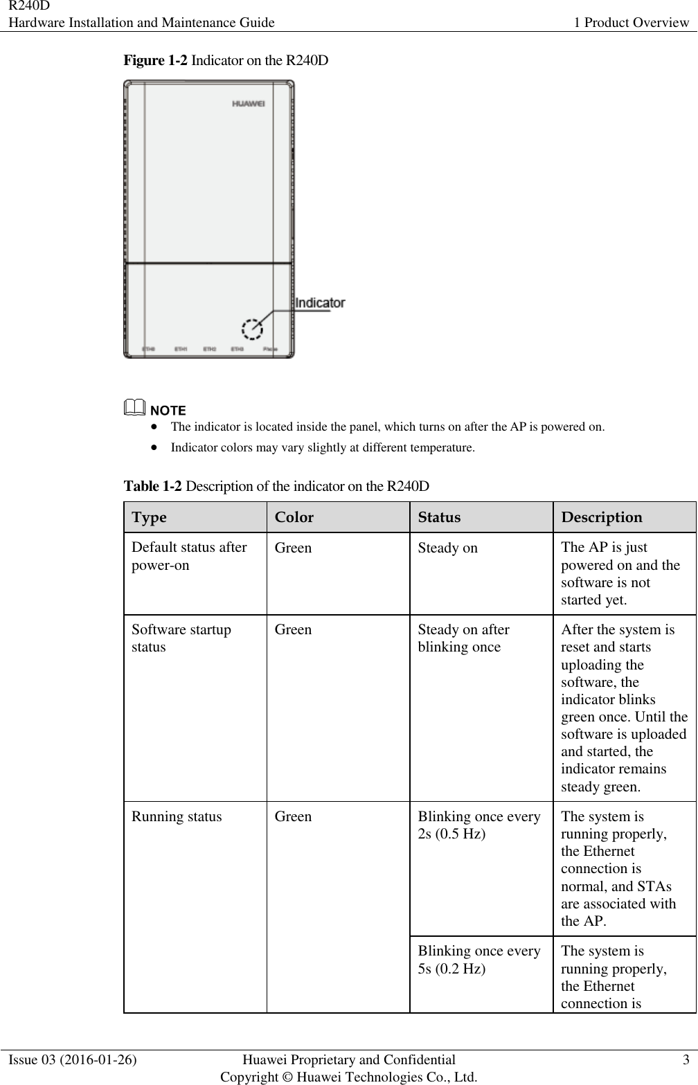
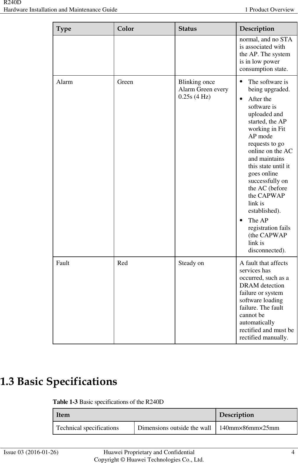
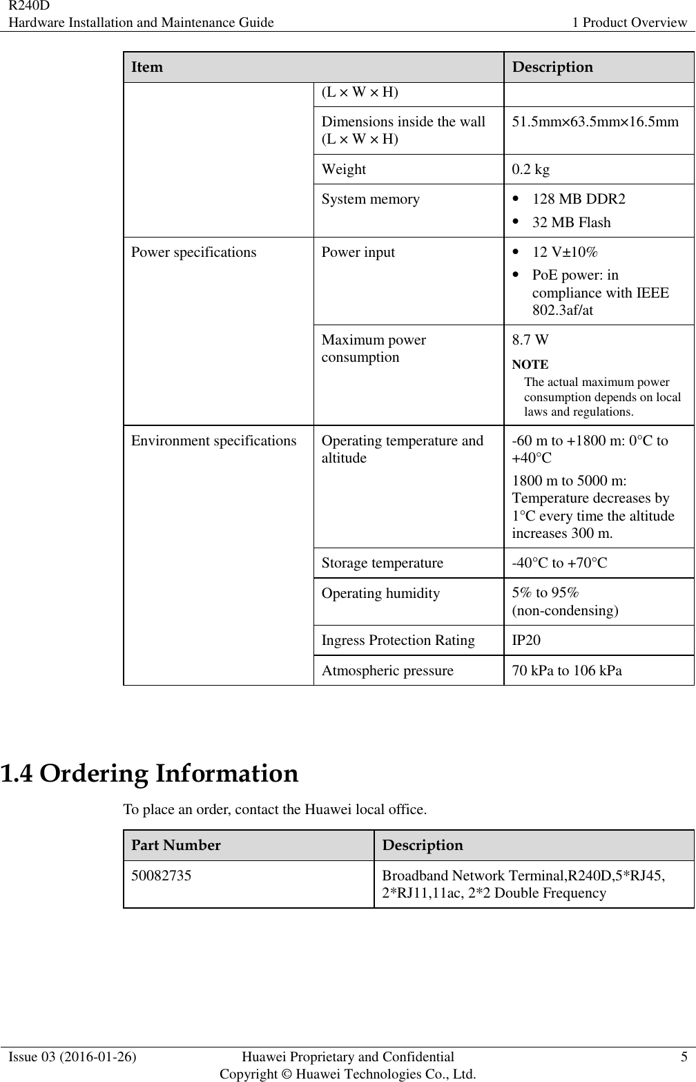
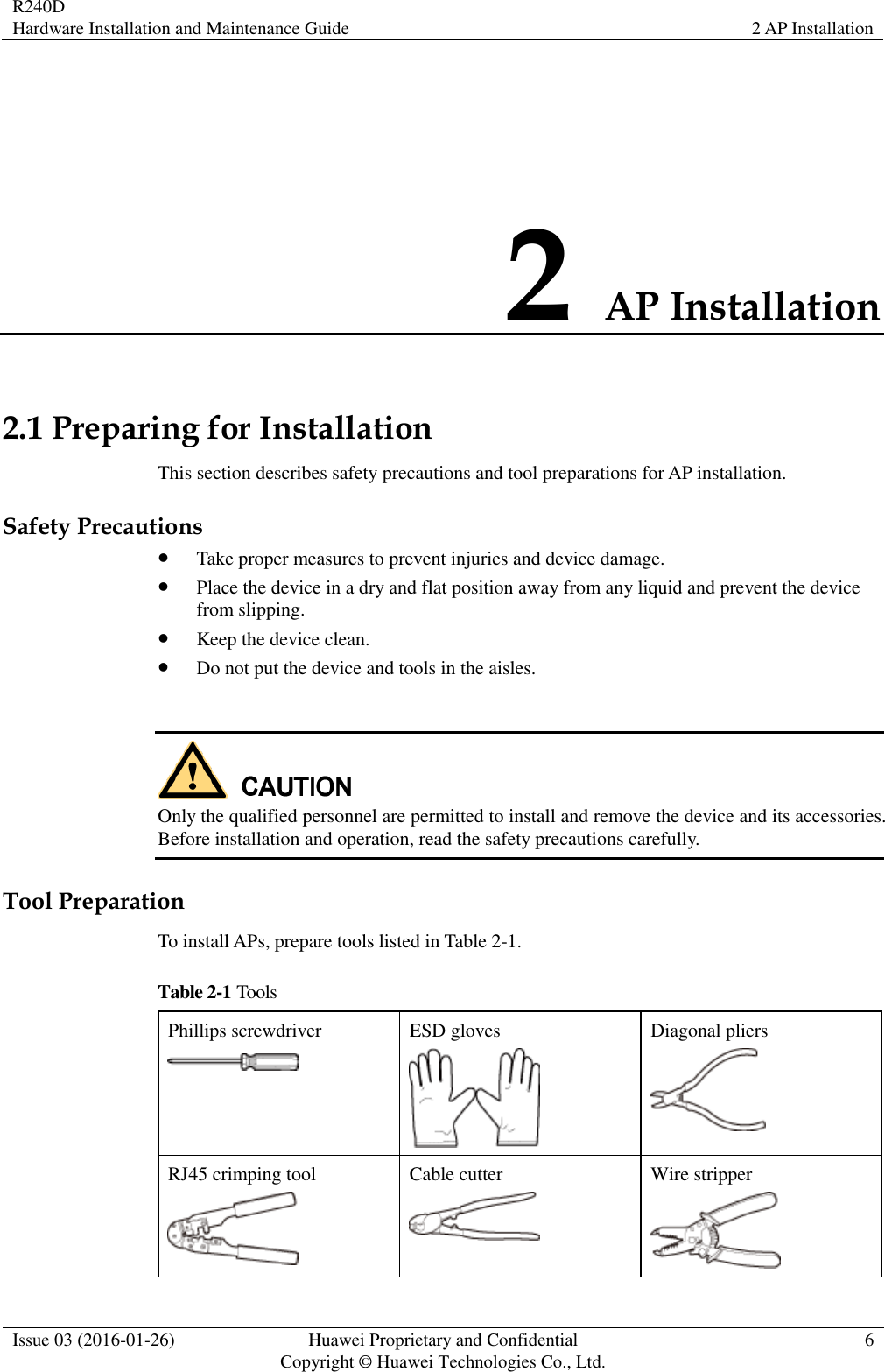
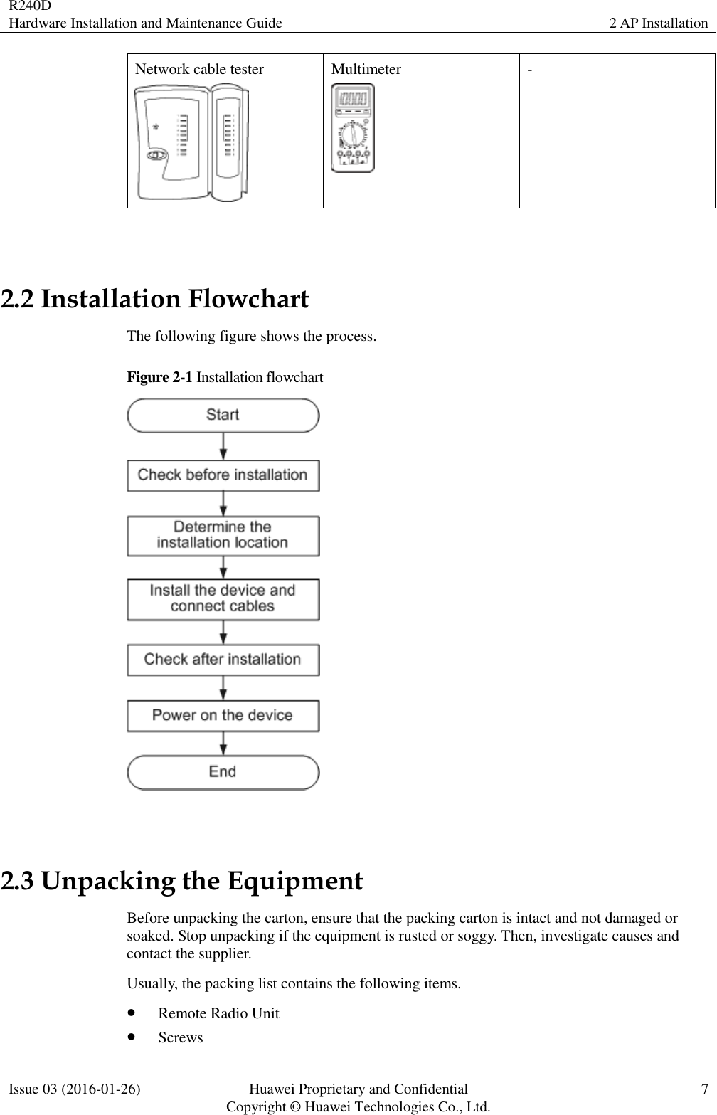
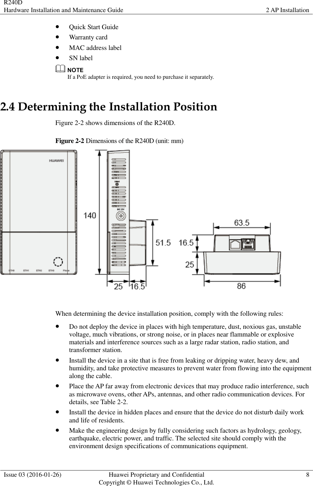
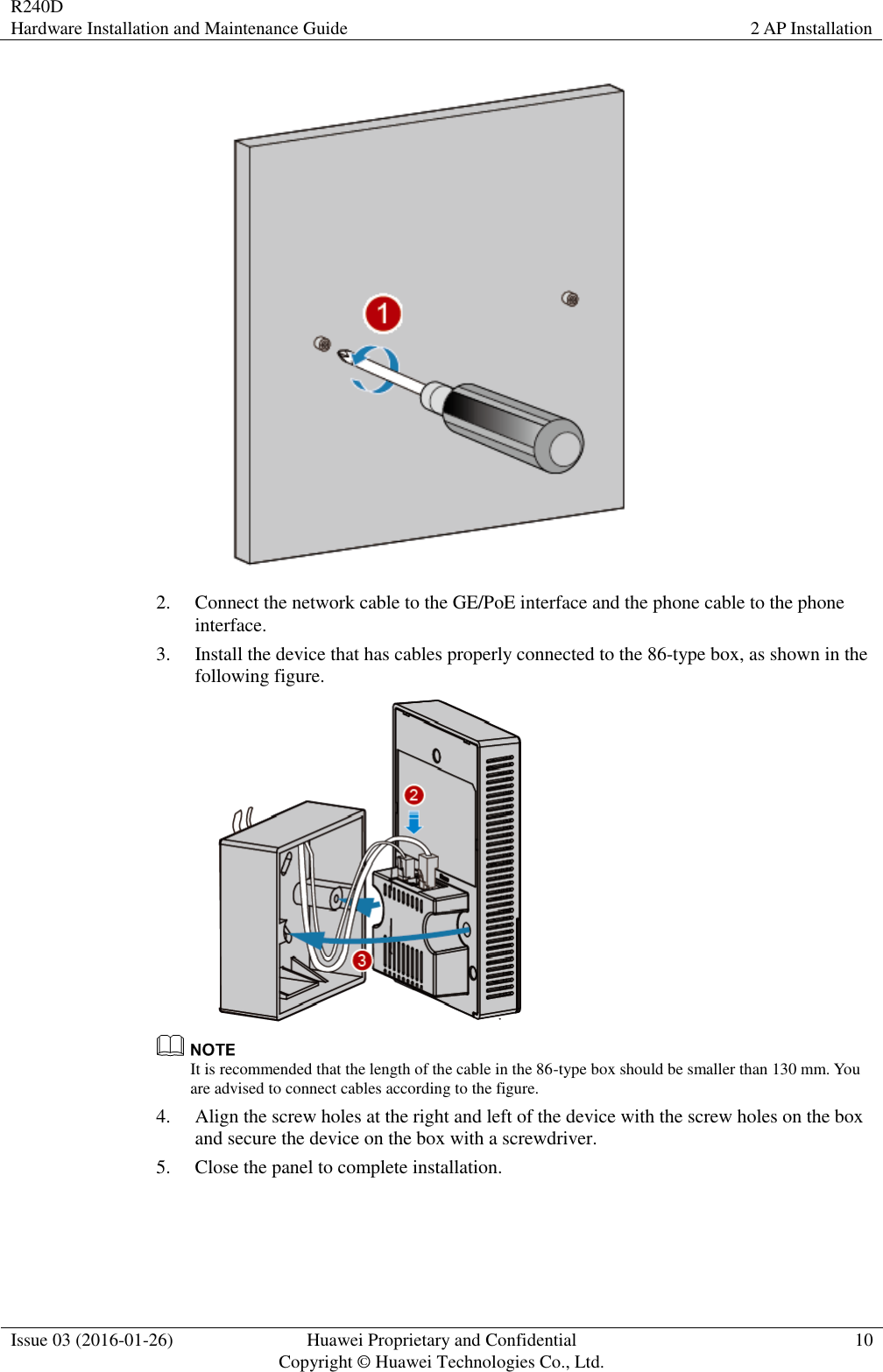
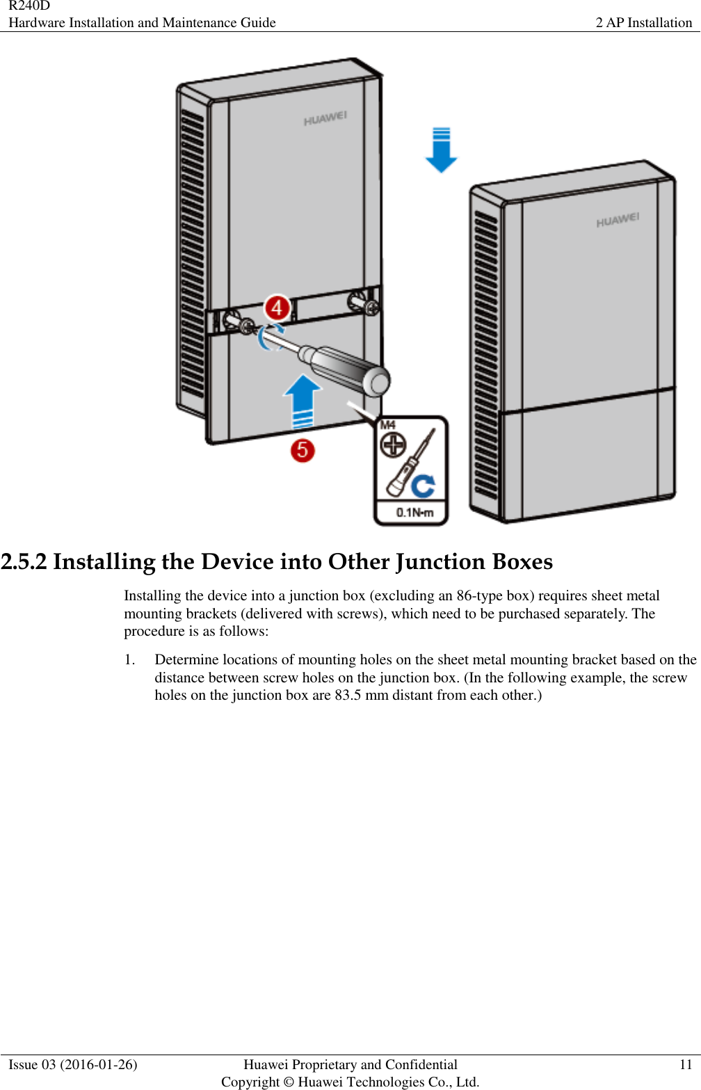
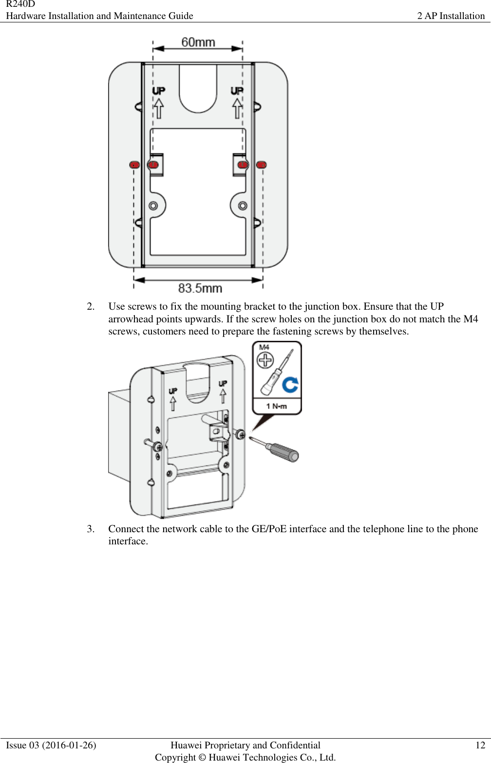
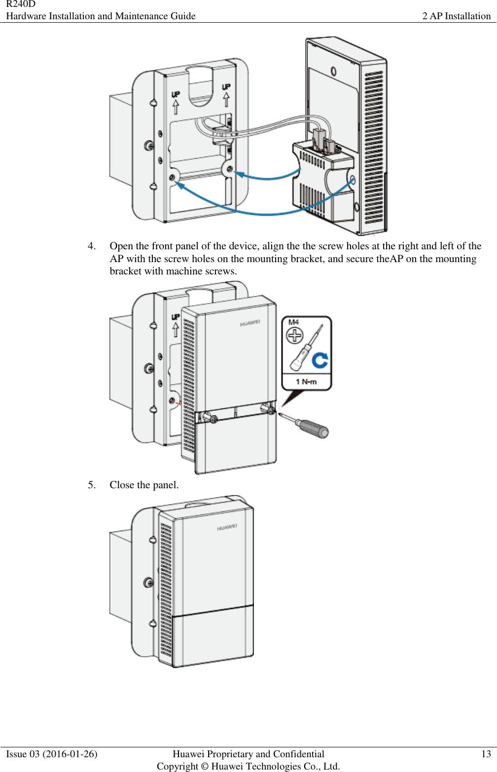
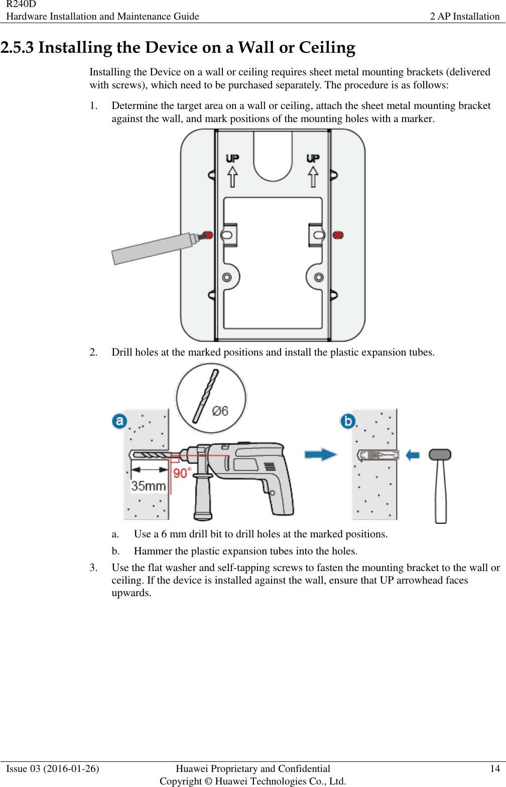
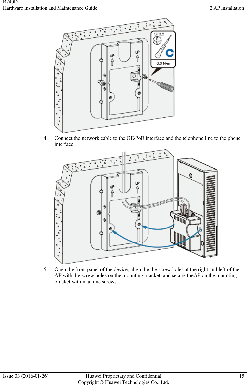
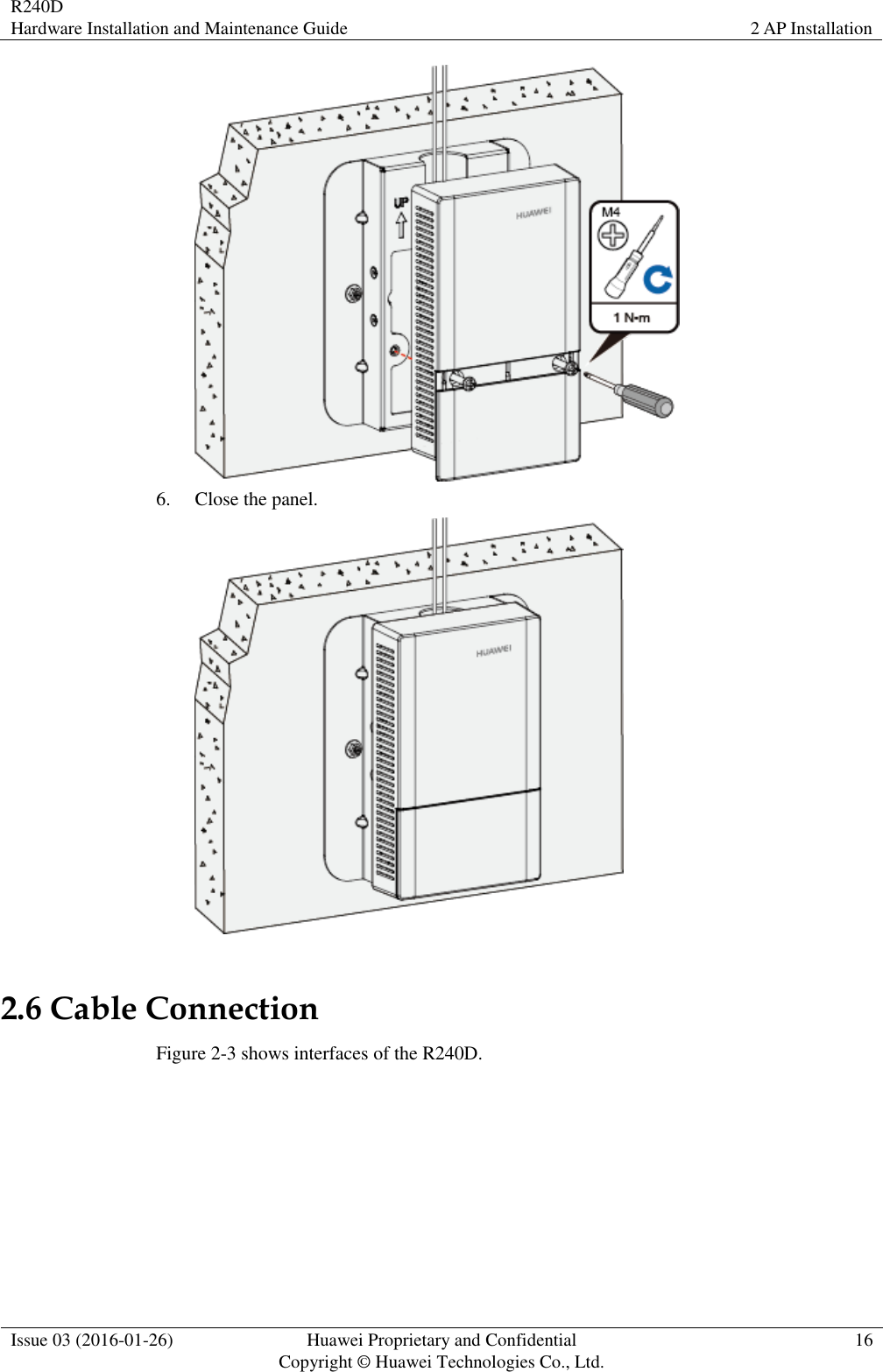
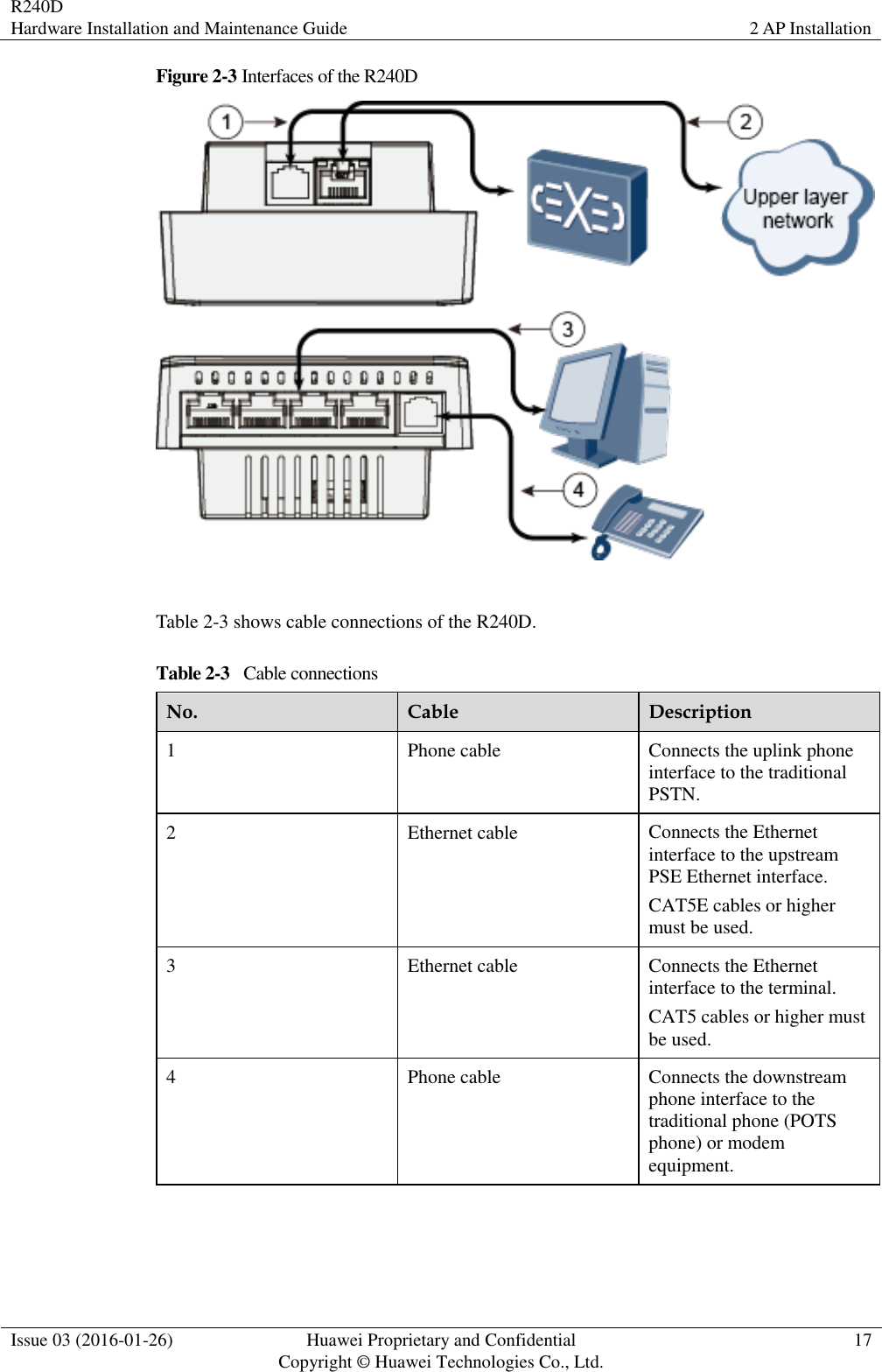
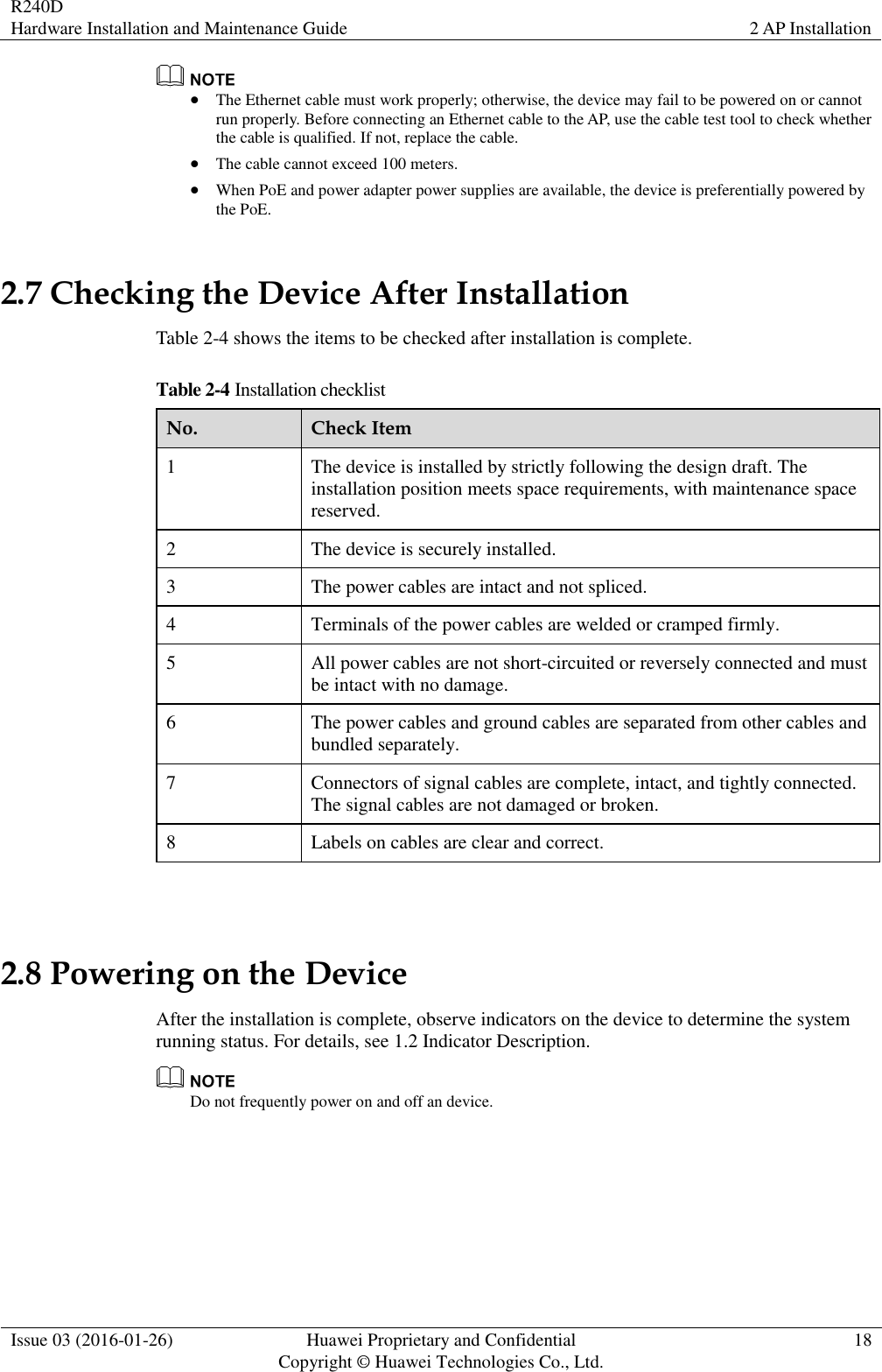
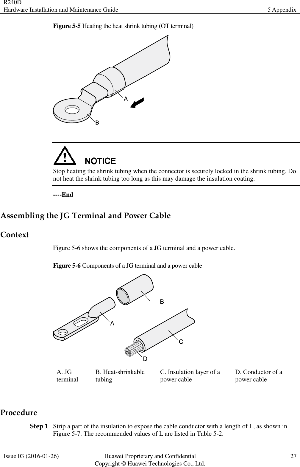
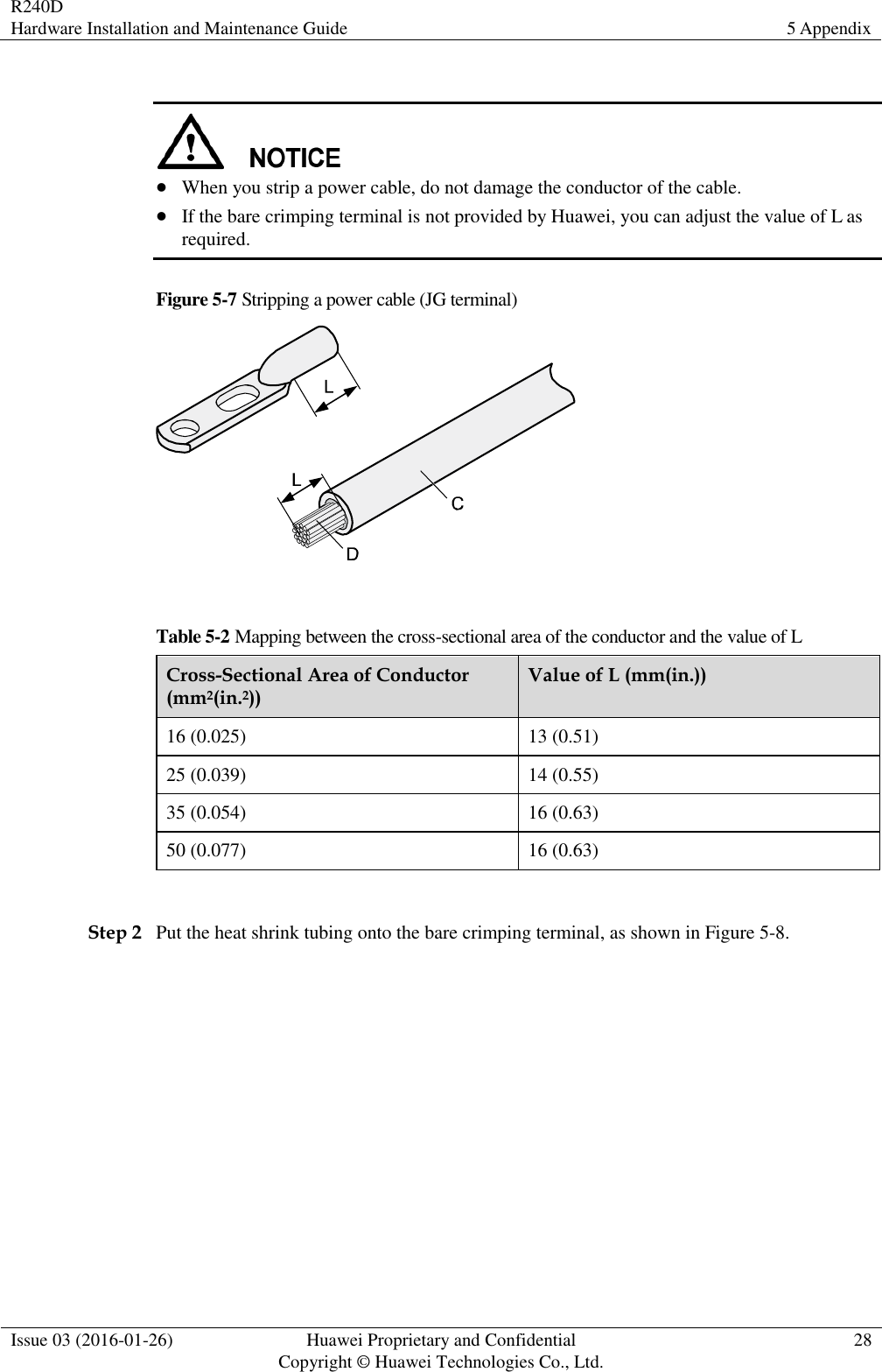
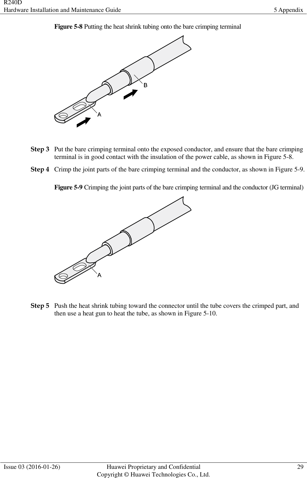
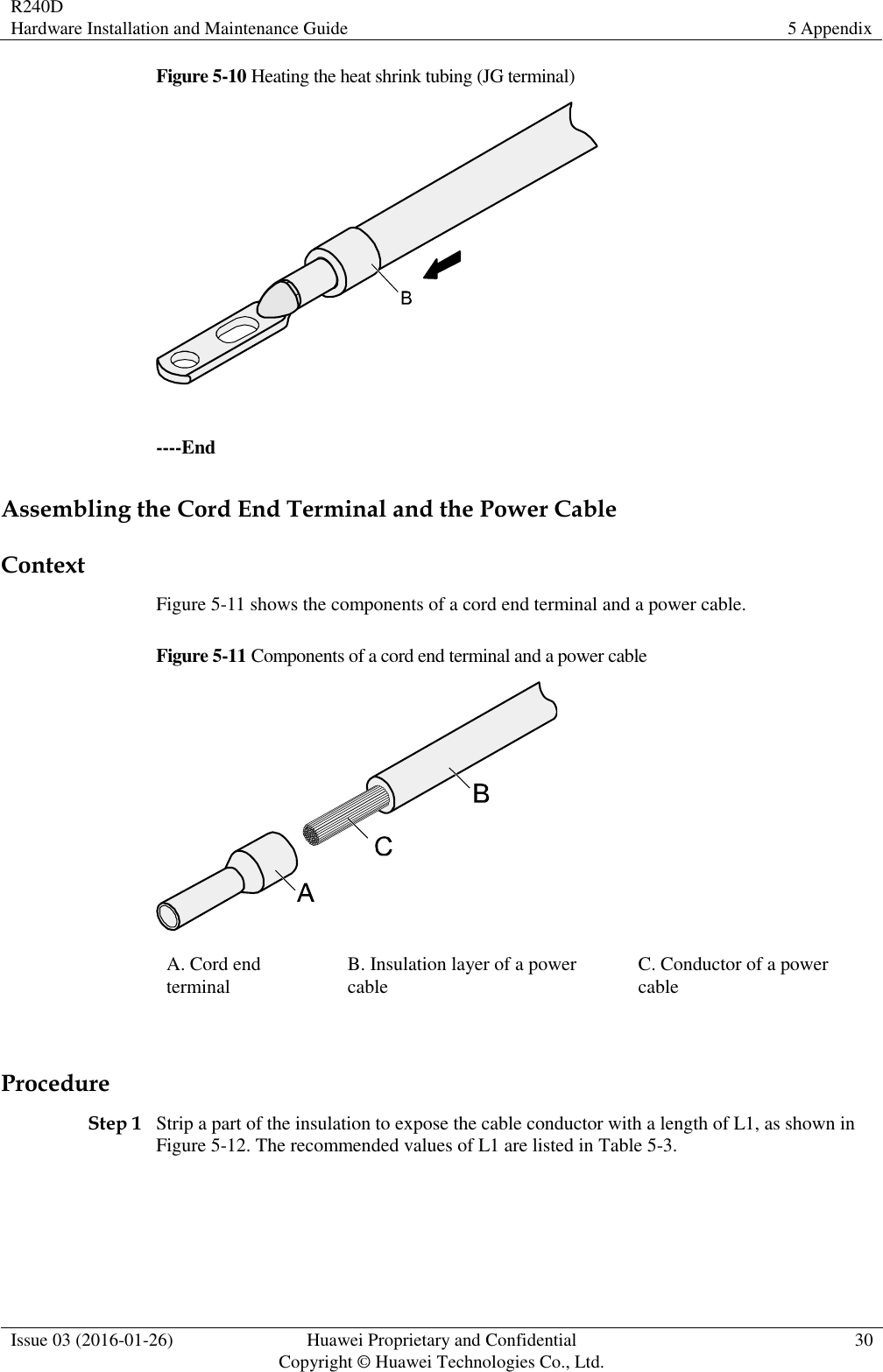
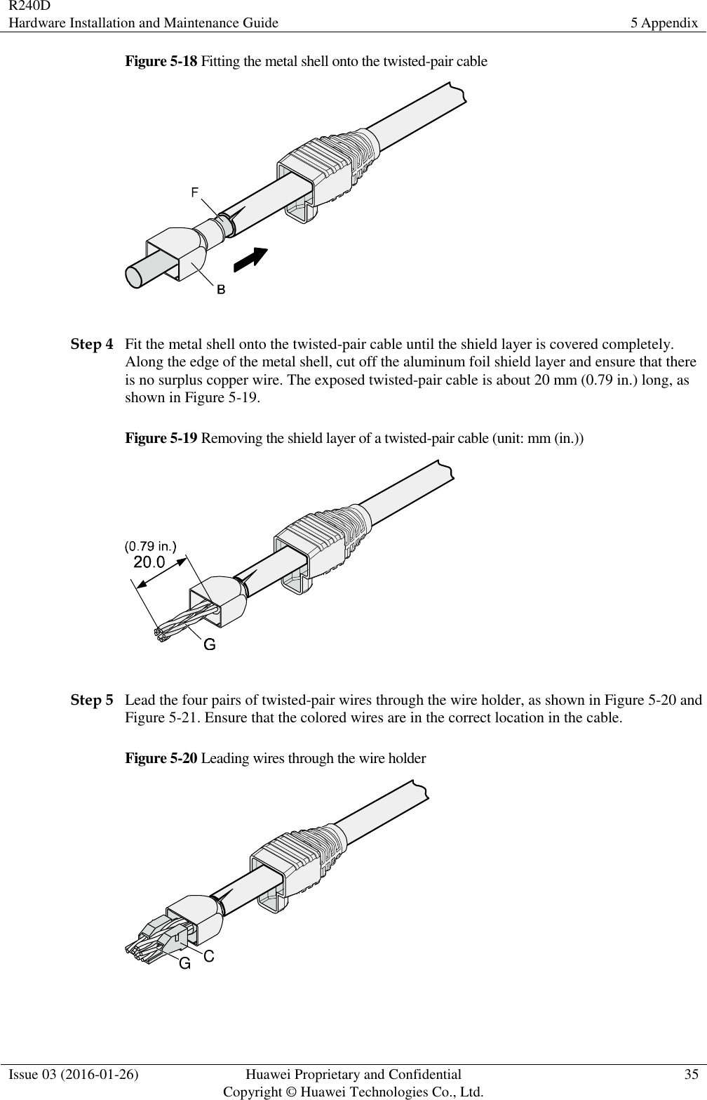
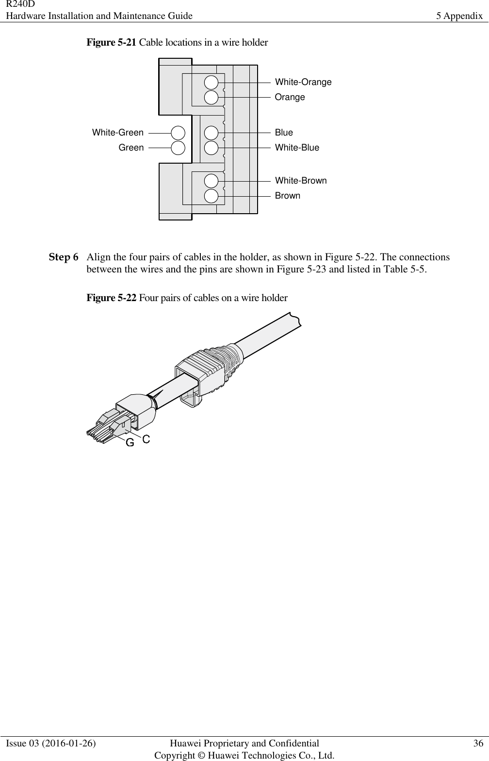
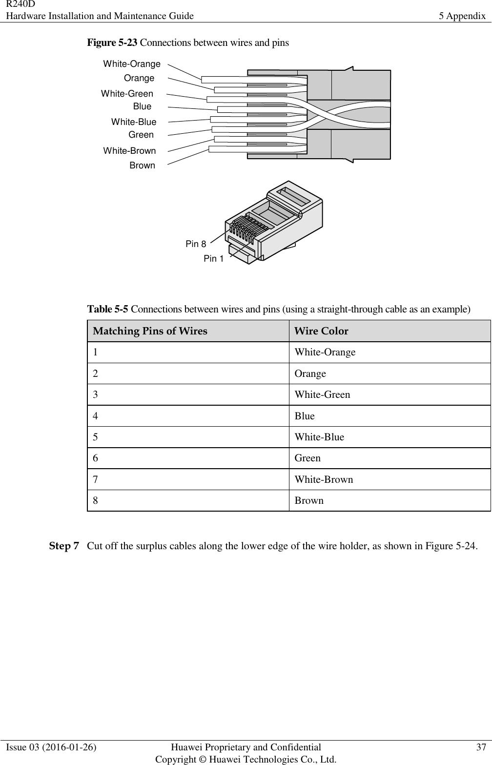
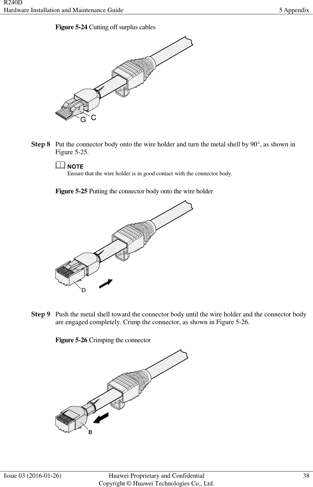
User manual_Hardware Installation and Maintenance Guide

        R240D  Hardware Installation and Maintenance Guide   Issue 03 Date 2016-01-26 HUAWEI TECHNOLOGIES CO., LTD.
 Issue 03 (2016-01-26) Huawei Proprietary and Confidential                                     Copyright © Huawei Technologies Co., Ltd. i    Copyright © Huawei Technologies Co., Ltd. 2016. All rights reserved. No part of this document may be reproduced or transmitted in any form or by any means without prior written consent of Huawei Technologies Co., Ltd.  Trademarks and Permissions   and other Huawei trademarks are trademarks of Huawei Technologies Co., Ltd. All other  trademarks  and  trade  names  mentioned  in  this document are  the  property of  their  respective holders.  Notice The purchased products, services and features are stipulated by the contract made between Huawei and the customer.  All or part of the products, services and features described in this document may not be within the purchase scope or the usage scope. Unless otherwise specified in the contract, all statements, information, and recommendations in this document are provided "AS IS" without warranties, guarantees or representations of any kind, either express or implied. The information in this document is subject to change without notice. Every effort has been made in the preparation  of  this  document  to  ensure  accuracy  of  the  contents,  but  all  statements,  information,  and recommendations in this document do not constitute a warranty of any kind, express or implied.     Huawei Technologies Co., Ltd. Address: Huawei Industrial Base Bantian, Longgang Shenzhen 518129 People's Republic of China Website: http://e.huawei.com
R240D Hardware Installation and Maintenance Guide About This Document  Issue 03 (2016-01-26) Huawei Proprietary and Confidential                                     Copyright © Huawei Technologies Co., Ltd. ii  About This Document Intended Audience This document describes hardware features of the R240D and provides basic installation methods. This document is intended for:  Network planning engineers  Hardware installation engineers  Commissioning engineers  Onsite maintenance engineers  System maintenance engineers Symbol Conventions The symbols that may be found in this document are defined as follows. Symbol Description  Indicates an imminently hazardous situation which, if not avoided, will result in death or serious injury.  Indicates a potentially hazardous situation which, if not avoided, could result in death or serious injury.  Indicates a potentially hazardous situation which, if not avoided, may result in minor or moderate injury.  Indicates a potentially hazardous situation which, if not avoided, could result in equipment damage, data loss, performance deterioration, or unanticipated results. NOTICE is used to address practices not related to personal injury.  Calls attention to important information, best practices and tips. NOTE is used to address information not
R240D Hardware Installation and Maintenance Guide About This Document  Issue 03 (2016-01-26) Huawei Proprietary and Confidential                                     Copyright © Huawei Technologies Co., Ltd. iii  Symbol Description related to personal injury, equipment damage, and environment deterioration.  Change History Changes between document issues are cumulative. The latest document issue contains all changes made in previous issues. Issue 03 (2016-01-26) This version has the following updates: Added the installation scenarios using sheet metal mounting brackets.  2.5.2 Installing the Device into Other Junction Boxes  2.5.3 Installing the Device on a Wall or Ceiling Issue 02 (2015-12-12) This version has the following updates: The installation tool list is updated. Issue 01 (2015-09-15) Initial commercial release.
R240D Hardware Installation and Maintenance Guide Contents  Issue 03 (2016-01-26) Huawei Proprietary and Confidential                                     Copyright © Huawei Technologies Co., Ltd. iv  Contents About This Document .................................................................................................................... ii 1 Product Overview ......................................................................................................................... 1 1.1 Device Structure ........................................................................................................................................................... 1 1.2 Indicator Description .................................................................................................................................................... 2 1.3 Basic Specifications ...................................................................................................................................................... 4 1.4 Ordering Information .................................................................................................................................................... 5 2 AP Installation ............................................................................................................................... 6 2.1 Preparing for Installation .............................................................................................................................................. 6 2.2 Installation Flowchart ................................................................................................................................................... 7 2.3 Unpacking the Equipment ............................................................................................................................................ 7 2.4 Determining the Installation Position ........................................................................................................................... 8 2.5 Installing the Device ..................................................................................................................................................... 9 2.5.1 Installing the Device into an 86-Type Box ................................................................................................................ 9 2.5.2 Installing the Device into Other Junction Boxes ..................................................................................................... 11 2.5.3 Installing the Device on a Wall or Ceiling ............................................................................................................... 14 2.6 Cable Connection ........................................................................................................................................................ 16 2.7 Checking the Device After Installation ....................................................................................................................... 18 2.8 Powering on the Device .............................................................................................................................................. 18 3 Logging In to the Device............................................................................................................ 19 3.1 Logging In to the Device Using STelnet/Telnet .......................................................................................................... 19 4 Hardware Failures ....................................................................................................................... 21 4.1 A Device Fails to Be Powered On............................................................................................................................... 21 5 Appendix ...................................................................................................................................... 23 5.1 On-site Cable Assembly and Installation .................................................................................................................... 23 5.1.1 Cable Assembly Precautions .................................................................................................................................... 23 5.1.2 Assembling Power Cables ....................................................................................................................................... 24 5.1.3 Assembling Ethernet Cables .................................................................................................................................... 33 5.1.4 Installing Cable Accessories .................................................................................................................................... 47 5.1.5 Replacing the Mold of the Crimping Tool ............................................................................................................... 63 5.2 Environmental Requirements for Device Operation ................................................................................................... 66 5.2.1 Environmental Requirements for an Equipment Room ........................................................................................... 66
R240D Hardware Installation and Maintenance Guide Contents  Issue 03 (2016-01-26) Huawei Proprietary and Confidential                                     Copyright © Huawei Technologies Co., Ltd. v  5.2.2 Requirements for Power Supply .............................................................................................................................. 74 5.3 Equipment Grounding Specifications ......................................................................................................................... 76 5.3.1 General Grounding Specifications ........................................................................................................................... 76 5.3.2 Grounding Specifications for an Equipment Room ................................................................................................. 77 5.3.3 Grounding Specifications for Devices ..................................................................................................................... 77 5.3.4 Grounding Specifications for Communications Power Supply ............................................................................... 77 5.3.5 Grounding Specifications for Signal Cables ............................................................................................................ 78 5.3.6 Specifications for Laying Out Grounding Cables .................................................................................................... 78 5.4 Engineering Labels for Cables .................................................................................................................................... 79 5.4.1 Introduction to Labels .............................................................................................................................................. 79 5.4.2 Engineering Labels for Optical Fibers ..................................................................................................................... 87 5.4.3 Engineering Labels for Network Cables .................................................................................................................. 90 5.4.4 Engineering Labels for User Cables ........................................................................................................................ 91 5.4.5 Engineering Labels for Power Cables ...................................................................................................................... 92 5.5 Guide to Using Optical Modules ................................................................................................................................ 95 5.6 Fault Tag ..................................................................................................................................................................... 98 5.7 Installation Checklist .................................................................................................................................................. 99
R240D Hardware Installation and Maintenance Guide 1 Product Overview  Issue 03 (2016-01-26) Huawei Proprietary and Confidential                                     Copyright © Huawei Technologies Co., Ltd. 1  1 Product Overview 1.1 Device Structure Figure 1-1 shows the appearance of the R240D. Figure 1-1 Appearance of the R240D   Table 1-1 describes interfaces on the R240D. Table 1-1 Interfaces on the R240D No. Name Description 1 Phone Phone interface: connects to a traditional PSTN. 2 GE/PoE 10/100/1000 Mbit/s interface: used to connect to the central AP and supports
R240D Hardware Installation and Maintenance Guide 1 Product Overview  Issue 03 (2016-01-26) Huawei Proprietary and Confidential                                     Copyright © Huawei Technologies Co., Ltd. 2  No. Name Description PoE power input. 3 ETH0 to ETH3 10/100 Mbit/s interface: connects to the wired Ethernet. Seen from the bottom, the four Ethernet interfaces are ETH0, ETH1, ETH2, and ETH3 from left to right. 4 Phone Phone interface: connects to a POTS phone or modem device. 5 Default Reset button: restores factory settings and restarts the device if you hold down the button more than 3 seconds. 6 DC 12 V The device supports the PoE power supply and DC power supply. To connect the device to a DC power source, use the power adapter delivered with the device; otherwise, the device maybe damaged.  1.2 Indicator Description R240D provides only one indicator, as shown in Figure 1-2.
R240D Hardware Installation and Maintenance Guide 1 Product Overview  Issue 03 (2016-01-26) Huawei Proprietary and Confidential                                     Copyright © Huawei Technologies Co., Ltd. 3  Figure 1-2 Indicator on the R240D     The indicator is located inside the panel, which turns on after the AP is powered on.  Indicator colors may vary slightly at different temperature. Table 1-2 Description of the indicator on the R240D Type Color Status Description Default status after power-on Green Steady on The AP is just powered on and the software is not started yet. Software startup status Green Steady on after blinking once After the system is reset and starts uploading the software, the indicator blinks green once. Until the software is uploaded and started, the indicator remains steady green. Running status Green Blinking once every 2s (0.5 Hz) The system is running properly, the Ethernet connection is normal, and STAs are associated with the AP. Blinking once every 5s (0.2 Hz) The system is running properly, the Ethernet connection is
R240D Hardware Installation and Maintenance Guide 1 Product Overview  Issue 03 (2016-01-26) Huawei Proprietary and Confidential                                     Copyright © Huawei Technologies Co., Ltd. 4  Type Color Status Description normal, and no STA is associated with the AP. The system is in low power consumption state. Alarm Green Blinking once Alarm Green every 0.25s (4 Hz)  The software is being upgraded.  After the software is uploaded and started, the AP working in Fit AP mode requests to go online on the AC and maintains this state until it goes online successfully on the AC (before the CAPWAP link is established).  The AP registration fails (the CAPWAP link is disconnected). Fault Red Steady on A fault that affects services has occurred, such as a DRAM detection failure or system software loading failure. The fault cannot be automatically rectified and must be rectified manually.  1.3 Basic Specifications Table 1-3 Basic specifications of the R240D Item Description Technical specifications Dimensions outside the wall 140mm×86mm×25mm
R240D Hardware Installation and Maintenance Guide 1 Product Overview  Issue 03 (2016-01-26) Huawei Proprietary and Confidential                                     Copyright © Huawei Technologies Co., Ltd. 5  Item Description (L × W × H) Dimensions inside the wall (L × W × H) 51.5mm×63.5mm×16.5mm Weight 0.2 kg System memory  128 MB DDR2  32 MB Flash Power specifications Power input  12 V±10%  PoE power: in compliance with IEEE 802.3af/at Maximum power consumption 8.7 W NOTE The actual maximum power consumption depends on local laws and regulations. Environment specifications Operating temperature and altitude -60 m to +1800 m: 0°C to +40°C 1800 m to 5000 m: Temperature decreases by 1°C every time the altitude increases 300 m. Storage temperature -40°C to +70°C Operating humidity 5% to 95% (non-condensing) Ingress Protection Rating IP20 Atmospheric pressure 70 kPa to 106 kPa  1.4 Ordering Information To place an order, contact the Huawei local office. Part Number Description 50082735 Broadband Network Terminal,R240D,5*RJ45, 2*RJ11,11ac, 2*2 Double Frequency
R240D Hardware Installation and Maintenance Guide 2 AP Installation  Issue 03 (2016-01-26) Huawei Proprietary and Confidential                                     Copyright © Huawei Technologies Co., Ltd. 6  2 AP Installation 2.1 Preparing for Installation This section describes safety precautions and tool preparations for AP installation.   Safety Precautions  Take proper measures to prevent injuries and device damage.    Place the device in a dry and flat position away from any liquid and prevent the device from slipping.  Keep the device clean.  Do not put the device and tools in the aisles.   Only the qualified personnel are permitted to install and remove the device and its accessories. Before installation and operation, read the safety precautions carefully.   Tool Preparation To install APs, prepare tools listed in Table 2-1. Table 2-1 Tools Phillips screwdriver  ESD gloves  Diagonal pliers  RJ45 crimping tool  Cable cutter  Wire stripper
R240D Hardware Installation and Maintenance Guide 2 AP Installation  Issue 03 (2016-01-26) Huawei Proprietary and Confidential                                     Copyright © Huawei Technologies Co., Ltd. 7  Network cable tester  Multimeter  -  2.2 Installation Flowchart The following figure shows the process. Figure 2-1 Installation flowchart   2.3 Unpacking the Equipment Before unpacking the carton, ensure that the packing carton is intact and not damaged or soaked. Stop unpacking if the equipment is rusted or soggy. Then, investigate causes and contact the supplier. Usually, the packing list contains the following items.  Remote Radio Unit  Screws
R240D Hardware Installation and Maintenance Guide 2 AP Installation  Issue 03 (2016-01-26) Huawei Proprietary and Confidential                                     Copyright © Huawei Technologies Co., Ltd. 8   Quick Start Guide  Warranty card  MAC address label  SN label  If a PoE adapter is required, you need to purchase it separately.   2.4 Determining the Installation Position Figure 2-2 shows dimensions of the R240D. Figure 2-2 Dimensions of the R240D (unit: mm)   When determining the device installation position, comply with the following rules:  Do not deploy the device in places with high temperature, dust, noxious gas, unstable voltage, much vibrations, or strong noise, or in places near flammable or explosive materials and interference sources such as a large radar station, radio station, and transformer station.  Install the device in a site that is free from leaking or dripping water, heavy dew, and humidity, and take protective measures to prevent water from flowing into the equipment along the cable.  Place the AP far away from electronic devices that may produce radio interference, such as microwave ovens, other APs, antennas, and other radio communication devices. For details, see Table 2-2.  Install the device in hidden places and ensure that the device do not disturb daily work and life of residents.  Make the engineering design by fully considering such factors as hydrology, geology, earthquake, electric power, and traffic. The selected site should comply with the environment design specifications of communications equipment.
R240D Hardware Installation and Maintenance Guide 2 AP Installation  Issue 03 (2016-01-26) Huawei Proprietary and Confidential                                     Copyright © Huawei Technologies Co., Ltd. 9   Indoor devices are usually mounted on a wall or ceiling using sheet metal mounting brackets. The installation position is determined by the site survey. Leave at least 200 mm of clearance around the device. Table 2-2 General anti-interference requirements Scenario Deployment Distance Requirement Indoor installation  There should be at least a 7 m distance between antennas.  The antennas should be placed at least 2 m from the 4G antennas of the carrier.  The antennas should be placed far away from electronic devices that may produce interference, such as microwave ovens.   If antennas are embedded into APs, the deployment distance requirements on the antennas are those on APs. 2.5 Installing the Device    The device should be isolated from strong electricity to ensure personal security and prevent device damages.  Remove the protective film on the surface before installation to prevent electrostatic   discharge. 2.5.1 Installing the Device into an 86-Type Box 1. Use a screwdriver to remove the 86-type panel from the wall (skip this step if no 86-type panel is installed on the wall).
R240D Hardware Installation and Maintenance Guide 2 AP Installation  Issue 03 (2016-01-26) Huawei Proprietary and Confidential                                     Copyright © Huawei Technologies Co., Ltd. 10   2. Connect the network cable to the GE/PoE interface and the phone cable to the phone interface. 3. Install the device that has cables properly connected to the 86-type box, as shown in the following figure.   It is recommended that the length of the cable in the 86-type box should be smaller than 130 mm. You are advised to connect cables according to the figure. 4. Align the screw holes at the right and left of the device with the screw holes on the box and secure the device on the box with a screwdriver. 5. Close the panel to complete installation.
R240D Hardware Installation and Maintenance Guide 2 AP Installation  Issue 03 (2016-01-26) Huawei Proprietary and Confidential                                     Copyright © Huawei Technologies Co., Ltd. 11   2.5.2 Installing the Device into Other Junction Boxes Installing the device into a junction box (excluding an 86-type box) requires sheet metal mounting brackets (delivered with screws), which need to be purchased separately. The procedure is as follows: 1. Determine locations of mounting holes on the sheet metal mounting bracket based on the distance between screw holes on the junction box. (In the following example, the screw holes on the junction box are 83.5 mm distant from each other.)
R240D Hardware Installation and Maintenance Guide 2 AP Installation  Issue 03 (2016-01-26) Huawei Proprietary and Confidential                                     Copyright © Huawei Technologies Co., Ltd. 12   2. Use screws to fix the mounting bracket to the junction box. Ensure that the UP arrowhead points upwards. If the screw holes on the junction box do not match the M4 screws, customers need to prepare the fastening screws by themselves.  3. Connect the network cable to the GE/PoE interface and the telephone line to the phone interface.
R240D Hardware Installation and Maintenance Guide 2 AP Installation  Issue 03 (2016-01-26) Huawei Proprietary and Confidential                                     Copyright © Huawei Technologies Co., Ltd. 13   4. Open the front panel of the device, align the the screw holes at the right and left of the AP with the screw holes on the mounting bracket, and secure theAP on the mounting bracket with machine screws.  5. Close the panel.
R240D Hardware Installation and Maintenance Guide 2 AP Installation  Issue 03 (2016-01-26) Huawei Proprietary and Confidential                                     Copyright © Huawei Technologies Co., Ltd. 14  2.5.3 Installing the Device on a Wall or Ceiling Installing the Device on a wall or ceiling requires sheet metal mounting brackets (delivered with screws), which need to be purchased separately. The procedure is as follows: 1. Determine the target area on a wall or ceiling, attach the sheet metal mounting bracket against the wall, and mark positions of the mounting holes with a marker.  2. Drill holes at the marked positions and install the plastic expansion tubes.  a. Use a 6 mm drill bit to drill holes at the marked positions. b. Hammer the plastic expansion tubes into the holes. 3. Use the flat washer and self-tapping screws to fasten the mounting bracket to the wall or ceiling. If the device is installed against the wall, ensure that UP arrowhead faces upwards.
R240D Hardware Installation and Maintenance Guide 2 AP Installation  Issue 03 (2016-01-26) Huawei Proprietary and Confidential                                     Copyright © Huawei Technologies Co., Ltd. 15   4. Connect the network cable to the GE/PoE interface and the telephone line to the phone interface.  5. Open the front panel of the device, align the the screw holes at the right and left of the AP with the screw holes on the mounting bracket, and secure theAP on the mounting bracket with machine screws.
R240D Hardware Installation and Maintenance Guide 2 AP Installation  Issue 03 (2016-01-26) Huawei Proprietary and Confidential                                     Copyright © Huawei Technologies Co., Ltd. 16   6. Close the panel.  2.6 Cable Connection Figure 2-3 shows interfaces of the R240D.
R240D Hardware Installation and Maintenance Guide 2 AP Installation  Issue 03 (2016-01-26) Huawei Proprietary and Confidential                                     Copyright © Huawei Technologies Co., Ltd. 17  Figure 2-3 Interfaces of the R240D   Table 2-3 shows cable connections of the R240D. Table 2-3   Cable connections No. Cable Description 1 Phone cable Connects the uplink phone interface to the traditional PSTN. 2 Ethernet cable Connects the Ethernet interface to the upstream PSE Ethernet interface. CAT5E cables or higher must be used. 3 Ethernet cable Connects the Ethernet interface to the terminal. CAT5 cables or higher must be used. 4 Phone cable Connects the downstream phone interface to the traditional phone (POTS phone) or modem equipment.
R240D Hardware Installation and Maintenance Guide 2 AP Installation  Issue 03 (2016-01-26) Huawei Proprietary and Confidential                                     Copyright © Huawei Technologies Co., Ltd. 18    The Ethernet cable must work properly; otherwise, the device may fail to be powered on or cannot run properly. Before connecting an Ethernet cable to the AP, use the cable test tool to check whether the cable is qualified. If not, replace the cable.  The cable cannot exceed 100 meters.  When PoE and power adapter power supplies are available, the device is preferentially powered by the PoE. 2.7 Checking the Device After Installation Table 2-4 shows the items to be checked after installation is complete. Table 2-4 Installation checklist No. Check Item 1 The device is installed by strictly following the design draft. The installation position meets space requirements, with maintenance space reserved. 2 The device is securely installed. 3 The power cables are intact and not spliced. 4 Terminals of the power cables are welded or cramped firmly. 5 All power cables are not short-circuited or reversely connected and must be intact with no damage. 6 The power cables and ground cables are separated from other cables and bundled separately. 7 Connectors of signal cables are complete, intact, and tightly connected. The signal cables are not damaged or broken. 8 Labels on cables are clear and correct.  2.8 Powering on the Device After the installation is complete, observe indicators on the device to determine the system running status. For details, see 1.2 Indicator Description.  Do not frequently power on and off an device.
R240D Hardware Installation and Maintenance Guide 3 Logging In to the Device  Issue 03 (2016-01-26) Huawei Proprietary and Confidential                                     Copyright © Huawei Technologies Co., Ltd. 19  3 Logging In to the Device 3.1 Logging In to the Device Using STelnet/Telnet You can log in to the device using STelnet V2 or Telnet to configure, manage, and maintain the device in the CLI.   By default, only the STelnet V2 service is enabled on the device.  Telnet has security vulnerabilities. You are not advised to enable the Telnet service. Before logging in to the device, complete the following tasks:  Power on the device.  Prepare network cables used to connect device interfaces. The following table lists the default configuration of the device. You are advised to change the default user name and password on your first login. Table 3-1 Default configuration of the device Parameter Default Setting User name admin Password admin@huawei.com IP address 169.254.1.1 Subnet mask 255.255.0.0   If the device is already online on the AC, you can remotely log in to the AC on a local terminal and run the display ap all command to check the IP address of the device. The following example uses the default parameters and is used for reference only. Step 1 Use network cables and a LAN switch to connect the PC to the network interface of the device. Step 2 Assign the PC with an IP address on the same network segment as the default IP address of the device so that the PC and device are reachable to each other.
R240D Hardware Installation and Maintenance Guide 3 Logging In to the Device  Issue 03 (2016-01-26) Huawei Proprietary and Confidential                                     Copyright © Huawei Technologies Co., Ltd. 20  If the device uses the default settings, the IP address of the PC must be in the network segment 169.254.0.0/16 but cannot be 169.254.1.1. 169.254.1.100 is recommended. Step 3 Start the CLI on the PC and access the IP address 169.254.1.1 of the device using STelnet V2. Step 4 Enter the user name and password as prompted to log in to the user interface. ----End
R240D Hardware Installation and Maintenance Guide 4 Hardware Failures  Issue 03 (2016-01-26) Huawei Proprietary and Confidential                                     Copyright © Huawei Technologies Co., Ltd. 21  4 Hardware Failures 4.1 A Device Fails to Be Powered On Fault Description The SYS indicator of a device is off. Possible Causes Power Supply Mode Possible Cause Power supply using a power module  The device is powered off.  The power cable is not securely connected to the device.  The power supply unit has failed. − If the device connects to an external power source, its power adapter may fail. − If the device has a built-in power supply, the device itself may be faulty. PoE power supply  The power sourcing equipment does not support the PoE function or is faulty.  The power sourcing equipment is incorrectly configured (the PoE function is disabled or the power-off time range is improperly set).  The line is faulty (the network cable or distribution frame is damaged).  The device is faulty.  Troubleshooting Procedure Power Supply Mode Troubleshooting Procedure
R240D Hardware Installation and Maintenance Guide 4 Hardware Failures  Issue 03 (2016-01-26) Huawei Proprietary and Confidential                                     Copyright © Huawei Technologies Co., Ltd. 22  Power Supply Mode Troubleshooting Procedure Power supply using a power module 1. Check whether the device is powered off. 2. Check that the power cable is securely connected to the device. 3. Check whether the power supply is normal. Replace the power adapter with a normal one. If the device is powered on, the original power adapter is faulty. Contact Huawei technical support or Huawei agent and ask them to replace the power adapter. 4. If the device still cannot be powered on, the device itself is faulty. Contact Huawei technical support or Huawei agent and ask them to replace the device. PoE power supply 1. Check whether the power sourcing equipment supports PoE or is faulty. 2. Check whether the configuration on the power sourcing equipment causes PoE power supply errors, such as the PoE function is disabled or the power-off time range is incorrectly set. 3. Check whether the network cable or distribution frame is faulty. 4. If the device still cannot be powered on, the device itself is faulty. Contact Huawei technical support engineers or Huawei agent and ask them to replace the device.
R240D Hardware Installation and Maintenance Guide 5 Appendix  Issue 03 (2016-01-26) Huawei Proprietary and Confidential                                     Copyright © Huawei Technologies Co., Ltd. 23  5 Appendix 5.1 On-site Cable Assembly and Installation 5.1.1 Cable Assembly Precautions Checking the Appearance of Cables  If the cable jacket or insulation is visibly dirty, clean it before assembly.  If the jacket or insulation of a cable has visible damage, irreparable scuffing, or other defects, do not use the cable.  If the shield layer of a cable is damaged, do not use the cable.  If the cable jacket or insulation cracks after the cable is bent or twisted, discard this cable and check whether other cables have the same problem. If other cables have the same problem, replace these cables. Checking the Appearance of Connectors  Do not use connectors with visible defects, damage, rust or scuffing.  Do not use connectors if their shells or pins have exposed part or uneven plating, or their pins are lost, broken, or bent.  Do not use connectors that have dirt on their pins or in their jacks or if there are conductors between pins or between pins and the shell. Precautions for Assembly  Use dedicated tools or tools delivered by Huawei and follow the methods given here during assembly.  Hold terminals of cables instead of pulling the cables themselves when installing or removing cable components.  Take the following precautions when cutting or stripping cables: − Make cables slightly longer than necessary. − Coil cables longer than 2 m (6.56 ft) after cutting. Bind and fasten the coils using bundling ropes. The inner diameters of the coils should be larger than 20 times the outer diameters of the cables.
R240D Hardware Installation and Maintenance Guide 5 Appendix  Issue 03 (2016-01-26) Huawei Proprietary and Confidential                                     Copyright © Huawei Technologies Co., Ltd. 24  − When stripping the jackets of cables, avoid damaging the shield layers (braid or aluminum foil), insulation, core conductors, and other jackets that do not need to be stripped. − After assembling cables, cut all visible cross sections of jackets to ensure that the cross sections are arranged neatly. − Do not touch the core conductors of cables with your hands. Terminate exposed conductors in a timely way after stripping off insulation so that the surface of the conductors does not become oxidized.  Take the following precautions when crimping and connecting cables or connectors: − The terminals and conductors should be connected tightly after they are crimped. They should not be moved or turned. − Cut all the exposed copper wires. − Try to avoid a second crimping of sleeves. − Keep all the conductors clean and aligned.  The connectors, cables, and tools provided by different vendors may be different. The figures in this document are for your reference only. 5.1.2 Assembling Power Cables Assembling the OT Terminal and Power Cable Context Figure 5-1 shows the components of an OT terminal and a power cable. Figure 5-1 Components of an OT terminal and a power cable  A. Heat-shrinkable tubing B. Bare crimping terminal C. Insulation D. Conductor  Procedure Step 1 Based on the cross-sectional area of the cable conductor, strip a length of insulation coating C to expose the conductor D of length L1, as shown in Figure 5-2. The recommended values of L1 are listed in Table 5-1.
R240D Hardware Installation and Maintenance Guide 5 Appendix  Issue 03 (2016-01-26) Huawei Proprietary and Confidential                                     Copyright © Huawei Technologies Co., Ltd. 25  Figure 5-2 Stripping a power cable (OT terminal)     When you strip a power cable, do not damage the conductor of the cable.  If the bare crimping terminal is not provided by Huawei, the value of L1 is 1 mm (0.04 in.) to 2 mm (0.08 in.) greater than the value of L. Table 5-1 Mapping between the cross-sectional area of the conductor and the value of L1 Cross-Sectional Area of Conductor (mm2(in.2)) Value of L1 (mm(in.)) Cross-Sectional Area of Conductor (mm2(in.2)) Value of L1 (mm(in.)) 1 (0.002) 7 (0.28) 10 (0.015) 11 (0.43) 1.5 (0.002) 7 (0.28) 16 (0.025) 13 (0.51) 2.5 (0.004) 7 (0.28) 25 (0.039) 14 (0.55) 4 (0.006) 8 (0.31) 35 (0.054) 16 (0.63) 6 (0.009) 9 (0.35) 50 (0.077) 16 (0.63)   If you are proficient in assembling OT terminals and power cables, you can obtain the value of L1 by comparing the part to be crimped with the power cable. Step 2 Put the heat-shrinkable (A) tubing onto the bare crimping terminal, as shown in Figure 5-3.
R240D Hardware Installation and Maintenance Guide 5 Appendix  Issue 03 (2016-01-26) Huawei Proprietary and Confidential                                     Copyright © Huawei Technologies Co., Ltd. 26  Figure 5-3 Putting the heat shrink tubing onto the bare crimping terminal   Step 3 Put the OT terminal B onto the exposed conductor, and ensure that the OT terminal is in good contact with the insulation coating C, as shown in Figure 5-3.   After the conductor is fed into the OT terminal, the protruding part of the conductor, or L2 in Figure 5-3, must not be longer than 2 mm (0.08 in.). Step 4 Crimp the joint parts of the bare crimping terminal and the conductor, as shown in Figure 5-4.  The shapes of crimped parts may vary with the crimping dies. Figure 5-4 Crimping the joint parts of the bare crimping terminal and the conductor (OT terminal)   Step 5 Push the heat shrink tubing (A) toward the connector until the tube covers the crimped part, and then use a heat gun to heat the tube, as shown in Figure 5-5.
R240D Hardware Installation and Maintenance Guide 5 Appendix  Issue 03 (2016-01-26) Huawei Proprietary and Confidential                                     Copyright © Huawei Technologies Co., Ltd. 27  Figure 5-5 Heating the heat shrink tubing (OT terminal)    Stop heating the shrink tubing when the connector is securely locked in the shrink tubing. Do not heat the shrink tubing too long as this may damage the insulation coating. ----End Assembling the JG Terminal and Power Cable Context Figure 5-6 shows the components of a JG terminal and a power cable. Figure 5-6 Components of a JG terminal and a power cable  A. JG terminal B. Heat-shrinkable tubing C. Insulation layer of a power cable D. Conductor of a power cable  Procedure Step 1 Strip a part of the insulation to expose the cable conductor with a length of L, as shown in Figure 5-7. The recommended values of L are listed in Table 5-2.
R240D Hardware Installation and Maintenance Guide 5 Appendix  Issue 03 (2016-01-26) Huawei Proprietary and Confidential                                     Copyright © Huawei Technologies Co., Ltd. 28     When you strip a power cable, do not damage the conductor of the cable.  If the bare crimping terminal is not provided by Huawei, you can adjust the value of L as required. Figure 5-7 Stripping a power cable (JG terminal)   Table 5-2 Mapping between the cross-sectional area of the conductor and the value of L Cross-Sectional Area of Conductor (mm2(in.2)) Value of L (mm(in.)) 16 (0.025) 13 (0.51) 25 (0.039) 14 (0.55) 35 (0.054) 16 (0.63) 50 (0.077) 16 (0.63)  Step 2 Put the heat shrink tubing onto the bare crimping terminal, as shown in Figure 5-8.
R240D Hardware Installation and Maintenance Guide 5 Appendix  Issue 03 (2016-01-26) Huawei Proprietary and Confidential                                     Copyright © Huawei Technologies Co., Ltd. 29  Figure 5-8 Putting the heat shrink tubing onto the bare crimping terminal   Step 3 Put the bare crimping terminal onto the exposed conductor, and ensure that the bare crimping terminal is in good contact with the insulation of the power cable, as shown in Figure 5-8. Step 4 Crimp the joint parts of the bare crimping terminal and the conductor, as shown in Figure 5-9. Figure 5-9 Crimping the joint parts of the bare crimping terminal and the conductor (JG terminal)   Step 5 Push the heat shrink tubing toward the connector until the tube covers the crimped part, and then use a heat gun to heat the tube, as shown in Figure 5-10.
R240D Hardware Installation and Maintenance Guide 5 Appendix  Issue 03 (2016-01-26) Huawei Proprietary and Confidential                                     Copyright © Huawei Technologies Co., Ltd. 30  Figure 5-10 Heating the heat shrink tubing (JG terminal)   ----End Assembling the Cord End Terminal and the Power Cable Context Figure 5-11 shows the components of a cord end terminal and a power cable. Figure 5-11 Components of a cord end terminal and a power cable  A. Cord end terminal B. Insulation layer of a power cable C. Conductor of a power cable  Procedure Step 1 Strip a part of the insulation to expose the cable conductor with a length of L1, as shown in Figure 5-12. The recommended values of L1 are listed in Table 5-3.
R240D Hardware Installation and Maintenance Guide 5 Appendix  Issue 03 (2016-01-26) Huawei Proprietary and Confidential                                     Copyright © Huawei Technologies Co., Ltd. 31   When you strip a power cable, do not damage the conductor of the cable. Figure 5-12 Stripping a power cable (cord end terminal)   Table 5-3 Mapping between the cross-sectional area of the conductor and the value of L1 Cross-Sectional Area of Conductor (mm2(in.2)) Value of L1 (mm(in.)) Cross-Sectional Area of Conductor (mm2(in.2)) Value of L1 (mm(in.)) 1 (0.002) 8 (0.31) 10 (0.015) 15 (0.59) 1.5 (0.002) 10 (0.39) 16 (0.025) 15 (0.59) 2.5 (0.004) 10 (0.39) 25 (0.039) 18 (0.71) 4 (0.006) 12 (0.47) 35 (0.054) 19 (0.75) 6 (0.009) 14 (0.55) 50 (0.077) 26 (1.02)  Step 2 Put the cord end terminal onto the conductor, and ensure that the conductor is aligned with the edge of the cord end terminal, as shown in Figure 5-13.   After the conductor is fed into the cord end terminal, the protruding part of the conductor must not be longer than 1 mm (0.04 in.).
R240D Hardware Installation and Maintenance Guide 5 Appendix  Issue 03 (2016-01-26) Huawei Proprietary and Confidential                                     Copyright © Huawei Technologies Co., Ltd. 32  Figure 5-13 Putting the cord end terminal onto the conductor   Step 3 Crimp the joint parts of the cord end terminal and the conductor, as shown in Figure 5-14. Figure 5-14 Crimping the cord end terminal and the conductor   Step 4 Check the maximum width of the tubular crimped terminal. The maximum width of a tubular crimped terminal is listed in Table 5-4. Table 5-4 Maximum width of a tubular crimped terminal Cross-Sectional Area of Tubular Terminal (mm2(in.2)) Maximum Width of Crimped Terminal W1 (mm(in.)) 0.25 (0.0004) 1 (0.04) 0.5 (0.0008) 1 (0.04) 1.0 (0.0015) 1.5 (0.06) 1.5 (0.0023) 1.5 (0.06) 2.5 (0.0039) 2.4 (0.09) 4 (0.006) 3.1 (0.12) 6 (0.009) 4 (0.16) 10 (0.015) 5.3 (0.21)
R240D Hardware Installation and Maintenance Guide 5 Appendix  Issue 03 (2016-01-26) Huawei Proprietary and Confidential                                     Copyright © Huawei Technologies Co., Ltd. 33  Cross-Sectional Area of Tubular Terminal (mm2(in.2)) Maximum Width of Crimped Terminal W1 (mm(in.)) 16 (0.025) 6 (0.24) 25 (0.039) 8.7 (0.34) 35 (0.054) 10 (0.39)  ----End 5.1.3 Assembling Ethernet Cables Assembling the Shielded RJ45 Connector and Ethernet Cable Context Figure 5-15 shows the components of an RJ45 connector and a shielded Ethernet cable. Figure 5-15 Shielded RJ45 connector and cable  A. Jacket of connector B. Metal shell of connector C. Wire holder of connector D. Plug of connector E. Jacket of Ethernet cable F. Shield layer of Ethernet cable G. Twisted-pair wires -  Procedure Step 1 Fit the jacket of the connector onto the Ethernet cable, as shown in Figure 5-16.
R240D Hardware Installation and Maintenance Guide 5 Appendix  Issue 03 (2016-01-26) Huawei Proprietary and Confidential                                     Copyright © Huawei Technologies Co., Ltd. 34  Figure 5-16 Fitting the jacket of the connector onto the Ethernet cable   Step 2 Remove a 30 mm (1.18 in.) long section of the jacket, cut off the nylon twine inside the jacket, and cut a no more than 5 mm (0.20 in.) cleft in the jacket, as shown in Figure 5-17.    When you remove a section of the jacket, do not damage the shield layer of the twisted-pair cable.  When you remove the shield layer, do not damage the insulation of the twisted-pair cable. Figure 5-17 Removing the jacket of a twisted-pair cable (unit: mm (in.))   Step 3 Fit the metal shell onto the twisted-pair cable. The shield layer is covered by the metal shell, as shown in Figure 5-18.
R240D Hardware Installation and Maintenance Guide 5 Appendix  Issue 03 (2016-01-26) Huawei Proprietary and Confidential                                     Copyright © Huawei Technologies Co., Ltd. 35  Figure 5-18 Fitting the metal shell onto the twisted-pair cable   Step 4 Fit the metal shell onto the twisted-pair cable until the shield layer is covered completely. Along the edge of the metal shell, cut off the aluminum foil shield layer and ensure that there is no surplus copper wire. The exposed twisted-pair cable is about 20 mm (0.79 in.) long, as shown in Figure 5-19. Figure 5-19 Removing the shield layer of a twisted-pair cable (unit: mm (in.))   Step 5 Lead the four pairs of twisted-pair wires through the wire holder, as shown in Figure 5-20 and Figure 5-21. Ensure that the colored wires are in the correct location in the cable. Figure 5-20 Leading wires through the wire holder CG
R240D Hardware Installation and Maintenance Guide 5 Appendix  Issue 03 (2016-01-26) Huawei Proprietary and Confidential                                     Copyright © Huawei Technologies Co., Ltd. 36  Figure 5-21 Cable locations in a wire holder White-GreenGreenWhite-OrangeOrangeBlueWhite-BlueWhite-BrownBrown  Step 6 Align the four pairs of cables in the holder, as shown in Figure 5-22. The connections between the wires and the pins are shown in Figure 5-23 and listed in Table 5-5. Figure 5-22 Four pairs of cables on a wire holder
R240D Hardware Installation and Maintenance Guide 5 Appendix  Issue 03 (2016-01-26) Huawei Proprietary and Confidential                                     Copyright © Huawei Technologies Co., Ltd. 37  Figure 5-23 Connections between wires and pins BrownWhite-BrownGreenWhite-BlueBlueWhite-GreenOrangeWhite-OrangePin 8Pin 1  Table 5-5 Connections between wires and pins (using a straight-through cable as an example) Matching Pins of Wires Wire Color 1 White-Orange 2 Orange 3 White-Green 4 Blue 5 White-Blue 6 Green 7 White-Brown 8 Brown  Step 7 Cut off the surplus cables along the lower edge of the wire holder, as shown in Figure 5-24.
R240D Hardware Installation and Maintenance Guide 5 Appendix  Issue 03 (2016-01-26) Huawei Proprietary and Confidential                                     Copyright © Huawei Technologies Co., Ltd. 38  Figure 5-24 Cutting off surplus cables   Step 8 Put the connector body onto the wire holder and turn the metal shell by 90°, as shown in Figure 5-25.  Ensure that the wire holder is in good contact with the connector body. Figure 5-25 Putting the connector body onto the wire holder   Step 9 Push the metal shell toward the connector body until the wire holder and the connector body are engaged completely. Crimp the connector, as shown in Figure 5-26. Figure 5-26 Crimping the connector
R240D Hardware Installation and Maintenance Guide 5 Appendix  Issue 03 (2016-01-26) Huawei Proprietary and Confidential                                     Copyright © Huawei Technologies Co., Ltd. 39  Step 10 Push the jacket towards the metal shell until the metal shell is covered. This completes the assembly of one end of the cable, as shown in Figure 5-27. Figure 5-27 Pushing the metal shell   Step 11 To complete the assembly of the other end, repeat Step 1 through Step 10. ----End Assembling an Unshielded RJ45 Connector and Ethernet Cable Context Figure 5-28 shows the components of an unshielded RJ45 connector and cable. Figure 5-28 Components of an unshielded RJ45 connector and cable ABC A. Plug of connector B. Jacket C. Twisted-pair wires  Procedure Step 1 Remove a 16-mm (0.63 in.) long section of the jacket, as shown in Figure 5-29.
R240D Hardware Installation and Maintenance Guide 5 Appendix  Issue 03 (2016-01-26) Huawei Proprietary and Confidential                                     Copyright © Huawei Technologies Co., Ltd. 40   When you remove the shield layer, do not damage the insulation of the twisted-pair cable. Figure 5-29 Removing the jacket of a twisted-pair cable (unit: mm (in.))   Step 2 Align the four pairs of wires and cut the ends neatly, as shown in Figure 5-30. The connections between the wires and the pins are listed in Table 5-6. Figure 5-30 Connections between wires and pins (unit: mm (in.)) C16White-OrangeWhite-GreenOrangeBlueWhite-BlueGreenWhite-BrownBrownPin 8Pin 1  Table 5-6 Connections between wires and pins (using a straight-through cable as an example) Matching Pins of Wires Wire Color 1 White-Orange 2 Orange 3 White-Green 4 Blue 5 White-Blue 6 Green 7 White-Brown 8 Brown  Step 3 Feed the cable into the plug, and crimp the connector, as shown in Figure 5-31.
R240D Hardware Installation and Maintenance Guide 5 Appendix  Issue 03 (2016-01-26) Huawei Proprietary and Confidential                                     Copyright © Huawei Technologies Co., Ltd. 41   When inserting the cable, check from the side or bore of the plug to ensure that the cable is completely seated in the plug. Figure 5-31 Crimping the connector   Step 4 To complete the assembly of the other end, repeat Step 1 through Step 3. ----End Checking the Appearance of Contact Strips Context  To ensure proper contact between the crimped wires and the wire conductors, the heights and sizes of the contact strips must be standard and the same.  The contact strips must be parallel to each other, with an offset of less than ± 5°. The top margin of a strip must be parallel to the axis of the connector, with an offset of less than ± 10°.  To ensure conductivity, the surface of the contact strips must be clean.  The contact strips must be in good contact with the RJ45 socket. The plastic separators must remain intact and be aligned.  The contact strip blade must extend beyond the ends of the wires. The ends of the wires must be in contact with the edge of the RJ45. The distance between them must be less than 0.5 mm (0.02 in.). Procedure Step 1 Hold the crimped connector, with the front side facing you, and check whether the contact strips are of the same height. The height should be 6.02 ± 0.13 mm (0.237 ± 0.005). If a measuring tool is not available, you can compare the connector with a standard connector. Figure 5-32 shows an unqualified piece, and Figure 5-33 shows a qualified piece.  All unqualified pieces must be crimped again.
R240D Hardware Installation and Maintenance Guide 5 Appendix  Issue 03 (2016-01-26) Huawei Proprietary and Confidential                                     Copyright © Huawei Technologies Co., Ltd. 42  Figure 5-32 Contact strips of different heights   Figure 5-33 Contact strips of the same height   Step 2 Hold an RJ45 connector and turn it 45°. Observe the top edges of the metal contact strips. Figure 5-34 shows an unqualified piece. Figure 5-34 Unparallel contact strips of different heights   Step 3 Check whether the contact strips are clean. If they are not clean and the dirt cannot be removed, replace it with a new RJ45 connector. Figure 5-35 shows an unqualified piece.
R240D Hardware Installation and Maintenance Guide 5 Appendix  Issue 03 (2016-01-26) Huawei Proprietary and Confidential                                     Copyright © Huawei Technologies Co., Ltd. 43  Figure 5-35 Dirt on a contract strip   Step 4 Check whether the contact strips and the plastic separators are well aligned and intact. If a separator is skewed and cannot be fixed, replace it with a new RJ45 connector. Figure 5-36 shows an unqualified piece. Figure 5-36 Skewed plastic separators   Step 5 Hold the connector with the side facing towards you, and check whether you can see the cross-sections of the wires. Ensure that the ends of the wires are in good contact with the edge of the RJ45, and that the contact strip blade extends beyond the ends of the wires and is crimped with the wires. If not, replace the connector. Figure 5-37 shows an unqualified piece. Figure 5-37 Wires not in good contact with the edge of the RJ45   ----End
R240D Hardware Installation and Maintenance Guide 5 Appendix  Issue 03 (2016-01-26) Huawei Proprietary and Confidential                                     Copyright © Huawei Technologies Co., Ltd. 44  Testing the Connection of Assembled Cables Context Huawei provides two types of Ethernet cables: straight-through cables and crossover cables.  Straight-through cables are connected in a one-to-one manner. They are used to connect terminals such as a computer or switch to network devices. Table 5-7 lists the connections of core wires in a straight-through cable. Table 5-7 Connections of core wires in a straight-through cable RJ45 Connector 1 RJ45 Connector 2 Core Wire Color Twisted or Not 2 2 Orange Twisted 1 1 Orange-White 6 6 Green Twisted 3 3 Green-White 4 4 Blue Twisted 5 5 Blue-White 8 8 Brown Twisted 7 7 Brown-White   Crossover cables are connected in a crossover manner. They are used to connect terminals such as two computers or switches. Table 5-8 lists the connections of core wires in a crossover cable. Table 5-8 Connections of core wires in a straight crossover cable RJ45 Connector 1 RJ45 Connector 2 Core Wire Color Twisted or Not 6 2 Orange Twisted 3 1 Orange-White 2 6 Green Twisted 1 3 Green-White 4 4 Blue Twisted 5 5 Blue-White 8 8 Brown Twisted 7 7 Brown-White  Figure 5-38 shows the pins of an RJ45 connector.
R240D Hardware Installation and Maintenance Guide 5 Appendix  Issue 03 (2016-01-26) Huawei Proprietary and Confidential                                     Copyright © Huawei Technologies Co., Ltd. 45  Figure 5-38 Pins of an RJ45 connector Pin8Pin1  Procedure Step 1 Feed both connectors of the cable into the ports of the cable tester. Step 2 After the connectors are properly inserted, turn on the tester. If the indicators from 1 to G turn on simultaneously, you can infer that the pins work normally and the wires are correctly connected.  Turn the switch to the S position to slow down lighting of the indicators so that you can see the indicators more clearly, as shown in Figure 5-39. Figure 5-39 Testing the conduction and connections of wires   Step 3 Gently shake the connector and repeat  错误!未找到引用源。  to check whether the metal ontact strips are in good contact with the core wires and Ethernet ports, as shown in Figure 5-40.
R240D Hardware Installation and Maintenance Guide 5 Appendix  Issue 03 (2016-01-26) Huawei Proprietary and Confidential                                     Copyright © Huawei Technologies Co., Ltd. 46  Figure 5-40 Checking the reliability   The procedure for testing a crossover cable is the same as that for testing a straight-through cable except for the sequence in which the indicators turn on, which depends on the wire connections of a crossover cable. The Ethernet cable is qualified if the indicators turn on in the following sequence: At the master (left) section of the tester, the indicators turn on in the sequence of 1-8-G. At the slave (right) section of the tester, the indicators turn on in the sequence of 3-6-1-4-5-2-7-8-G. If the indicators do not come on in this sequence, the Ethernet cable is unqualified.  If a tester is not available, you can use a multimeter to perform a simple test, as shown in Figure 5-41. Figure 5-41 Testing the connection of an Ethernet cable
R240D Hardware Installation and Maintenance Guide 5 Appendix  Issue 03 (2016-01-26) Huawei Proprietary and Confidential                                     Copyright © Huawei Technologies Co., Ltd. 47  ----End 5.1.4 Installing Cable Accessories Precautions for Installing Cable Accessories Tools  The illustrations in this document may differ from actual situations, but the installation methods are the same. For example, in this document, the adapters of cable connectors have separate interfaces. In the actual situation, the adapters may have interfaces fixed on equipment. Use dedicated tools provided or specified by Huawei and follow the installation procedure described here. Bending Radius Unless otherwise specified, bending radius (R) of cables or fibers must meet the requirements listed in Table 5-9. Table 5-9 Bending radius of cables or fibers Cable or Fiber Bending Radius (R) Ordinary cable In normal cases, R ≥ 2d. When the cable is connected with a connector, R ≥ 5d. Fiber R ≥ 40 mm (1.57 in.); Bending angle > 90°   The letter d indicates the diameter of a cable or fiber. Precautions for Installation  Hold terminals of cables instead of pulling the cables themselves when installing or removing cable components.  Do not insert a connector forcibly when the connector is blocked. Use a dedicated tool to pull out the connector. Install the connector again after you check that the pins are inserted properly.  Before tightening screws on cable connectors, ensure that the connectors are properly connected to their adapters. Tighten the screw with appropriate force using a flat-head or Phillips screwdriver instead of bare hands or an electric screwdriver. If the screw cannot be screwed into the tapped hole, determine the reason and try again. Do not apply too much force, or the screw or adapter may be damaged.  When removing densely aligned cables or fiber connectors, use dedicated pliers such as cable-pulling pliers and fiber-pulling pliers.  Do not twist, bend, stretch, or extrude fibers during installation.  Cover the idle fiber connectors with dust caps. Remove the dust caps before using the fiber connectors.
R240D Hardware Installation and Maintenance Guide 5 Appendix  Issue 03 (2016-01-26) Huawei Proprietary and Confidential                                     Copyright © Huawei Technologies Co., Ltd. 48  Requirements for Cable Routing  To protect cables, remove the burrs in the cable through-holes or install protective rings in the holes.  To ease the connection and to avoid stress, keep cable joints slack. After connecting multiple cables to a connector that has multiple interfaces, keep the cables slack to avoid generating stress.  Bind or clean cables gently because cable distortion affects signal quality.  Keep cables away from moveable components such as doors.  Sharp objects must not touch cable wiring to prevent damage to cables.  To protect power cables, route power cables of the active and standby power modules separately. Installing Power Adapters Installing the OT Terminal Procedure  Install an OT terminal. a. Align the hole of the OT terminal (conductor upward) with a connecting hole, as shown in Figure 5-42. Figure 5-42 Aligning the OT terminal with a connecting hole    When you install an OT terminal, the crimping sleeve is installed as shown in Figure 5-43, where A is correct and B is incorrect.
R240D Hardware Installation and Maintenance Guide 5 Appendix  Issue 03 (2016-01-26) Huawei Proprietary and Confidential                                     Copyright © Huawei Technologies Co., Ltd. 49  Figure 5-43 Installing an OT terminal, showing the orientation of crimping sleeve   b. Place the spring washer and flat washer in turn, mount a matching screw, and fasten it clockwise, as shown in Figure 5-44. Figure 5-44 Installing two terminals back to back    Ensure that the OT terminal is not in contact with other terminals or metal components. c. Move the cable slightly and ensure that it is securely connected, as shown in Figure 5-45.
R240D Hardware Installation and Maintenance Guide 5 Appendix  Issue 03 (2016-01-26) Huawei Proprietary and Confidential                                     Copyright © Huawei Technologies Co., Ltd. 50  Figure 5-45 Installed OT terminal    Install two OT terminals on a post. Before you install two OT terminals on a post, ensure that the two terminals can be installed on the post and that the electrical connecting pieces have a large contact area. Two OT terminals can be installed using any of these methods: − Bend the upper OT terminal at a 45- or 90-degree angle, as shown in Figure 5-46. − Cross the two terminals, as shown in Figure 5-47. Figure 5-46 Bending the upper OT terminal at a 45- or 90-degree angle
R240D Hardware Installation and Maintenance Guide 5 Appendix  Issue 03 (2016-01-26) Huawei Proprietary and Confidential                                     Copyright © Huawei Technologies Co., Ltd. 51  Figure 5-47 Crossing two terminals    If the two terminals are different sizes, place the smaller one above the bigger one. A maximum of two terminals can be installed on a post.  To remove an OT terminal, loosen the screw counterclockwise. ----End Installing the Cord End Terminal Procedure Step 1 Hold a cord end terminal upright and place it on a terminal jack, as shown in Figure 5-48. To ensure bump contact and dense connection, place the plain side of the terminal outwards. Figure 5-48 Placing a terminal on a terminal jack vertically   Step 2 Insert the terminal into the jack vertically, and turn the screw clockwise to fasten the terminal, as shown in Figure 5-49.
R240D Hardware Installation and Maintenance Guide 5 Appendix  Issue 03 (2016-01-26) Huawei Proprietary and Confidential                                     Copyright © Huawei Technologies Co., Ltd. 52  Figure 5-49 Feeding the terminal into the jack     Ensure that the exposed section of the terminal is less than 2 mm (0.079 in.) in length.  Do not press the insulation of the terminal.  Insert only one terminal into one jack. Step 3 Move the cable slightly and ensure that it is securely connected. Step 4 Before you remove a cord end terminal, loosen the screw counterclockwise. ----End Installing Ethernet Adapters Installing a Shielded Ethernet Connector Procedure Step 1 Hold the male and female connectors, with the male connector facing the female connector, as shown in Figure 5-50. Figure 5-50 Holding the male and female shielded connectors   Step 2 Insert the male connector into the female connector, as shown in Figure 5-51.
R240D Hardware Installation and Maintenance Guide 5 Appendix  Issue 03 (2016-01-26) Huawei Proprietary and Confidential                                     Copyright © Huawei Technologies Co., Ltd. 53  Figure 5-51 Feeding the male shielded connector into the female shielded connector   Step 3 When you hear a click, the cable connector is completely inserted in the port. (The clip on the cable connector pops up to fix the connector in the port.) Pull the connector slightly and ensure that it is securely connected, as shown in Figure 5-52. Figure 5-52 Installed shielded Ethernet connector   Step 4 To remove an Ethernet connector, press the locking key and pull out the connector, as shown in Figure 5-53.
R240D Hardware Installation and Maintenance Guide 5 Appendix  Issue 03 (2016-01-26) Huawei Proprietary and Confidential                                     Copyright © Huawei Technologies Co., Ltd. 54  Figure 5-53 Removing a shielded Ethernet connector   ----End Installing an Unshielded Ethernet Connector Procedure Step 1 Hold the male and female connectors, with the male connector facing the female connector, as shown in Figure 5-54. Figure 5-54 Holding the male and female unshielded connectors   Step 2 Feed the male connector into the female connector, as shown in Figure 5-55.
R240D Hardware Installation and Maintenance Guide 5 Appendix  Issue 03 (2016-01-26) Huawei Proprietary and Confidential                                     Copyright © Huawei Technologies Co., Ltd. 55  Figure 5-55 Feeding the male connector into the female unshielded connector   Step 3 A crisp click indicates that the connector is locked by the locking key. Pull the connector slightly and ensure that it is securely connected. Figure 5-56 shows an installed Ethernet connector. Figure 5-56 Installed unshielded Ethernet connector   Step 4 To remove an Ethernet connector, press the locking key and pull out the connector, as shown in Figure 5-57.
R240D Hardware Installation and Maintenance Guide 5 Appendix  Issue 03 (2016-01-26) Huawei Proprietary and Confidential                                     Copyright © Huawei Technologies Co., Ltd. 56  Figure 5-57 Removing an unshielded Ethernet connector   ----End Installing Fiber Connectors Context    After you remove the dustproof cap, ensure that the fiber pins are clean and install them as soon as possible.  When you disassemble fiber connectors, you must use a dedicated tool if the connectors are densely installed. Cleaning Fiber Connectors Procedure Step 1 Clean the pins of a fiber connector by using lint-free cotton and alcohol. Step 2 Clean the pins again by using dust-free cotton. If necessary, clean the pins by using an air gun. Ensure that the pins are free from any fiber or debris. ----End Installing an FC Fiber Connector Procedure Step 1 Remove the dustproof cap of the FC connector and store it for future use. Step 2 Align the core pin of the male connector with that of the female connector, as shown in Figure 5-58.
R240D Hardware Installation and Maintenance Guide 5 Appendix  Issue 03 (2016-01-26) Huawei Proprietary and Confidential                                     Copyright © Huawei Technologies Co., Ltd. 57  Figure 5-58 Aligning the male connector with the female connector   Step 3 Align the male connector with the female connector and gently push the male connector until it is completely seated in the female connector, as shown in Figure 5-59. Figure 5-59 Feeding the male connector into the female connector   Step 4 Fasten the locking nut clockwise and ensure that the connector is securely installed, as shown in Figure 5-60.
R240D Hardware Installation and Maintenance Guide 5 Appendix  Issue 03 (2016-01-26) Huawei Proprietary and Confidential                                     Copyright © Huawei Technologies Co., Ltd. 58  Figure 5-60 Fastening the locking nut   Step 5 To disassemble an FC fiber connector, loosen the locking nut counterclockwise, and gently pull the male connector, as shown in Figure 5-61. Figure 5-61 Disassembling an FC fiber connector   ----End Installing an LC Fiber Connector Procedure Step 1 Remove the dustproof cap of the LC fiber connector and store it for future use. Step 2 Align the core pin of the male connector with that of the female connector, as shown in Figure 5-62.
R240D Hardware Installation and Maintenance Guide 5 Appendix  Issue 03 (2016-01-26) Huawei Proprietary and Confidential                                     Copyright © Huawei Technologies Co., Ltd. 59  Figure 5-62 Aligning the male connector with the female connector   Step 3 Align the male connector with the fiber adapter and gently push the male connector until it is completely seated in the fiber connector, as shown in Figure 5-63. Figure 5-63 Feeding the male connector into the female connector   Step 4 A clicking sound indicates that the male connector is locked, as shown in Figure 5-64. Figure 5-64 Installed LC connector   Step 5 To disassemble an LC fiber connector, press the locking nut to release the locking clips from the bore, and gently pull the male connector, as shown in Figure 5-65.
R240D Hardware Installation and Maintenance Guide 5 Appendix  Issue 03 (2016-01-26) Huawei Proprietary and Confidential                                     Copyright © Huawei Technologies Co., Ltd. 60  Figure 5-65 Disassembling an LC fiber connector   ----End Installing the SC Fiber Connector Procedure Step 1 Remove the dustproof cap of the SC fiber connector and store it for future use. Step 2 Align the core pin of the male connector with that of the female connector, as shown in Figure 5-66. Figure 5-66 Aligning the male connector with the female connector   Step 3 Feed the fiber connector into the female connector, with your fingers holding the shell of the fiber connector (not the pigtail). When you hear a click, the fiber connector is secured by the clips (internal parts, not illustrated in the figure). Pull the fiber connector gently. If the connector does not loosen, the installation is complete. See Figure 5-67.
R240D Hardware Installation and Maintenance Guide 5 Appendix  Issue 03 (2016-01-26) Huawei Proprietary and Confidential                                     Copyright © Huawei Technologies Co., Ltd. 61  Figure 5-67 Installed SC fiber connector   Step 4 To disassemble an SC fiber connector, hold the shell of the connector (do not hold the fiber) and gently pull the connector in the direction vertical to the adapter. Unlock the male connector, and then separate it from the shell, as shown in Figure 5-68. Figure 5-68 Disassembling an SC fiber connector   ----End Installing an MPO Connector Procedure Step 1 Remove the dustproof cap of the MPO fiber connector and store it for future use. Step 2 Align the core pin of the male connector with that of the female connector, as shown in Figure 5-69.
R240D Hardware Installation and Maintenance Guide 5 Appendix  Issue 03 (2016-01-26) Huawei Proprietary and Confidential                                     Copyright © Huawei Technologies Co., Ltd. 62  Figure 5-69 Aligning the male connector with the female connector   Step 3 Hold the shell labeled "PUSH" and feed the male connector into the female connector until you hear a clicking sound. The male and female connectors are securely installed, as shown in Figure 5-70. Figure 5-70 Installed MPO fiber connector   Step 4 To disassemble an MPO fiber connector, hold the shell labeled "PULL" and remove the male connector, as shown in Figure 5-71.
R240D Hardware Installation and Maintenance Guide 5 Appendix  Issue 03 (2016-01-26) Huawei Proprietary and Confidential                                     Copyright © Huawei Technologies Co., Ltd. 63  Figure 5-71 Disassembling an MPO fiber connector   ----End 5.1.5 Replacing the Mold of the Crimping Tool Procedure Step 1 Hold the handles of a pair of COAX crimping tools. Loosen the two fastening screws counterclockwise, as shown in Figure 5-72. Figure 5-72 Loosening two fastening screws   Step 2 Hold the handles of the COAX crimping tools to open the self-locking mechanism. The jaw of the COAX crimping tools opens automatically, as shown in Figure 5-73.
R240D Hardware Installation and Maintenance Guide 5 Appendix  Issue 03 (2016-01-26) Huawei Proprietary and Confidential                                     Copyright © Huawei Technologies Co., Ltd. 64  Figure 5-73 Pliers jaw opening automatically   Step 3 Remove the mold from the COAX crimping tools, as shown in Figure 5-74. Figure 5-74 Removing the mold from the COAX crimping tools   Step 4 Place the mold to be installed into the jaw of the COAX crimping tools and align the screw holes, as shown in Figure 5-75.
R240D Hardware Installation and Maintenance Guide 5 Appendix  Issue 03 (2016-01-26) Huawei Proprietary and Confidential                                     Copyright © Huawei Technologies Co., Ltd. 65  Figure 5-75 Installing a new mold in the COAX crimping tool    Keep the short side of the mold inwards and the long side outwards, with the teeth of the mold aligning from the larger size to the smaller size. Step 5 Hold the handles of the COAX crimping tools tightly to match the mold and the jaw completely. Align the screw holes, as shown in Figure 5-76. Figure 5-76 Aligning the screw holes   Step 6 Hold the handles of the COAX crimping tools with one hand. Tighten the two fastening screws clockwise. Figure 5-77 and Figure 5-78shows the mold installed in the COAX crimping tool.
R240D Hardware Installation and Maintenance Guide 5 Appendix  Issue 03 (2016-01-26) Huawei Proprietary and Confidential                                     Copyright © Huawei Technologies Co., Ltd. 66  Figure 5-77 Mold installed in the COAX crimping tool   Figure 5-78 An installed mold   ----End 5.2 Environmental Requirements for Device Operation 5.2.1 Environmental Requirements for an Equipment Room Requirements for Selecting a Site for an Equipment Room When designing a project, consider the communication network planning and technical requirements of the equipment. Also consider hydrographic, geological, seismic, power supply, and transportation factors. Construction, structure, heating and ventilation, power supply, lighting and fire-proof construction of the equipment room should be designed by specialized construction designers to suit the environmental requirements of devices. The equipment room should also follow local regulations concerning the industrial construction, environmental protection, fire safety, and civil air defense. Construction must conform to government standards, regulations, and other requirements. The equipment room should be located in a place free from high temperature, dust, toxic gases, explosive materials, or unstable voltage. Keep the equipment room away from significant vibrations or loud noises, as well as power transformer stations.
R240D Hardware Installation and Maintenance Guide 5 Appendix  Issue 03 (2016-01-26) Huawei Proprietary and Confidential                                     Copyright © Huawei Technologies Co., Ltd. 67  The specific requirements for selecting a site for an equipment room are as follows:  The room should be located at a distance of at least 5 km (3.11 mi.) from heavy pollution sources such as smelting and coal mines. It should be located at a distance of at least 3.7 km (2.30 mi.) from moderate pollution sources such as chemical, rubber, and galvanization factories. It should be located at a distance of at least 2 km (1.24 mi.) from light pollution sources such as packinghouses and tanyards. If these pollution sources cannot be avoided, ensure that the equipment room is upwind of the pollution sources. In addition, use a high-quality equipment room or protection products.  The room should be located away from livestock farms, or be upwind of the livestock farms. Do not use an old livestock room or fertilizer warehouse as the equipment room.  The equipment room must be far away from residential areas. An equipment room that is not far away from residential areas must comply with equipment room construction standards to avoid noise pollution.  The room should be located far away from industrial and heating boilers.  The room should be at least 3.7 km (2.30 mi.) away from the seaside or salt lake. Otherwise, the equipment room should be airtight with cooling facilities. In addition, alkalized soil cannot be used as the construction material. Otherwise, equipment suitable for wet conditions must be used.  The doors and windows of the equipment room must be kept closed to maintain an airtight room.  Using steel doors to ensure sound insulation is recommended.  No cracks or openings are allowed on the walls or floors. The outlet holes on the walls or windows must be sealed. Walls must be constructed such that they are smooth, wear-resistant, dustproof, flame retardant, sound insulated, heat absorptive, and have electromagnetic shielding.  The air vent of the room should be far from the exhaust of city waste pipes, big cesspools and sewage treatment tanks. The room should be in the positive pressure state to prevent corrosive gases from entering the equipment room and corroding components and circuit boards.  It is recommended that the room be on or above the second floor. If this requirement cannot be met, the ground for equipment installation in the room should be at least 600 mm (23.62 in,) above the maximum flood level.    The equipment room should be strong enough to resist winds and downpours.  The room should be located away from dusty roads or sand. If this is unavoidable, the doors and windows of the equipment room must not face pollution sources.  Do not place air conditioning vents near the equipment so that they blow directly on the equipment because condensation may be blown into the equipment.  Do not use decorative materials that contain sulfur in the equipment room. Equipment Room Layout An equipment room usually contains mobile switching equipment, telecommunications equipment, power supply equipment, and other auxiliary equipment. To ensure easy maintenance and management, place the equipment in different rooms. Figure 5-79 shows the layout of the equipment room.
R240D Hardware Installation and Maintenance Guide 5 Appendix  Issue 03 (2016-01-26) Huawei Proprietary and Confidential                                     Copyright © Huawei Technologies Co., Ltd. 68  Figure 5-79 Layout of the equipment room Control room Generator roomTransmissionroom Main communicationequipment room Power distributionroom Battery roomSubstation room Communication cable and optical cablePower cable  The general layout principles of the equipment room are as follows:  It should meet requirements for laying out and maintaining communication cables and power cables.  It should reduce the cabling distance, which facilitates cable maintenance, reduces potential communication faults, and maximizes efficiency. Construction Requirements for the Equipment Room Table 5-10 describes the construction requirements for the equipment room. Table 5-10 Construction requirements for the equipment room Item Requirements Area The smallest area of the equipment room can accommodate the equipment with the largest capacity. Net height The minimum height of the equipment room should not be less than 3 m (9.84 ft). The minimum height of the equipment room is the net height below overhead beams or ventilation pipes.   Floor The floor in the equipment room should be semi-conductive and dustproof. A raised floor with an ESD covering is recommended. Cover the raised floor tightly and solidly. The horizontal tolerance of each square meter should be less than 2 mm (0.08 in.). If raised floors are unavailable, use a static-electricity-conductive floor material, with a volume resistivity of 1.0 x 10⁷ ohms to 1.0 x 10¹⁰ ohms. Ground this floor material or raised floor. You can connect them to ground using a one megohm current-limiting resistor and connection line. Load-bearing capacity The floor must bear loads larger than 150 kg/m2 (0.21 bf/in.2).   Door and windows The door of the equipment room should be 2 m (6.56 ft) high and 1 m (3.28 ft) wide. One door is enough. Seal the doors and windows with
R240D Hardware Installation and Maintenance Guide 5 Appendix  Issue 03 (2016-01-26) Huawei Proprietary and Confidential                                     Copyright © Huawei Technologies Co., Ltd. 69  Item Requirements dustproof plastic tape. Use double-pane glass in the windows and seal them tightly. Wall surface treatment Paste wallpaper on the wall or apply flat paint. Do not use pulverized paint. Cable trays Use cable trays to arrange cables. The inner faces of the cable trays must be smooth. The reserved length and width of the cable trays, and the number, position and dimensions of the holes must comply with the requirements of device arrangement. Water pipe Do not pass service pipes, drainpipes, and storm sewers through the equipment room. Do not place a fire hydrant in the equipment room, but place it in the corridor or near the staircase. Internal partition wall Separate the area where the equipment is installed from the equipment room door. The partition wall can block some outside dust. Installation position of the air conditioner Install air conditioner vents so that the air does not blow directly on equipment. Other requirements Avoid the proliferation of mildew, and keep out rodents (like mice).  Figure 5-80 Internal partition wall inside the equipment room   Equipment Room Environment Dust on devices may cause electrostatic discharge and result in poor contact for connectors or metal connection points. This problem can shorten the life span of devices and cause faults. The equipment room must be free from explosive, conductive, magnetically-permeable, and corrosive dust. Table 5-11 lists the requirement for dust concentration in the equipment room.
R240D Hardware Installation and Maintenance Guide 5 Appendix  Issue 03 (2016-01-26) Huawei Proprietary and Confidential                                     Copyright © Huawei Technologies Co., Ltd. 70  Table 5-11 Requirements for dust particles in the equipment room Mechanical active material Unit Concentration Dust particle Particle /m3 ≤ 3x 10⁴ (no visible dust accumulated on a workbench in three days) Suspending dust mg/m3 ≤0.2 Precipitable dust mg/m2·h  ≤1.5 Description  Dust particle diameter ≥ 5 µm  Suspending dust diameter ≤ 75 µm  75 µm ≤ precipitable dust diameter ≤ 150 µm  Take the following measures to meet the requirements:  Use dustproof materials for ground, wall, and ceiling construction.  Use screens on the door and windows facing outside. The outer windows should be dust-proof.  Clean the equipment room regularly and clean the air filter monthly.  Wear shoe covers and ESD clothing before entering the equipment room. Requirements for Corrosive Gases The room should be free from dusts and corrosive gases, such as SO2, H2S, and NH3. Table 5-12 lists the requirements for the corrosive gas concentration. Table 5-12 Requirements for corrosive gas concentration Chemical active material Unit Concentration SO2 mg/m3 ≤0.20 H2S mg/m3 ≤0.006 NH3 mg/m3 ≤0.05 Cl2 mg/m3 ≤0.01  Take the following measures to meet the requirements:  Avoid constructing the room near a place where the corrosive gas concentration is high, such as a chemical plant.  Ensure the air intake vent of the room is in the prevailing upwind direction from any pollution source.
R240D Hardware Installation and Maintenance Guide 5 Appendix  Issue 03 (2016-01-26) Huawei Proprietary and Confidential                                     Copyright © Huawei Technologies Co., Ltd. 71   Place batteries in different rooms.  A professional service should monitor the corrosive gas conditions regularly. Requirements for ESD Prevention The absolute value of electrostatic voltage must be less than 1000 V. Take the following measures to meet this requirement:  Train operators about ESD prevention.  Keep the correct humidity level in the equipment room to reduce the impact of static electricity.  Lay out an ESD floor in equipment rooms.  Wear ESD shoes and clothing before entering equipment room.  Use ESD tools, such as wrist straps, tweezers, and pullers.  Ground all conductive materials in the room, including computer terminals. Use ESD worktables.  Keep non-ESD materials (such as common bags, foam, and rubber) at least 30 cm (11.81 in.) away from boards and ESD-sensitive components. Electromagnetism Requirements for the Equipment Room All interference sources, inside or outside the equipment room, can cause equipment problems with capacitive coupling, inductive coupling, electromagnetic wave radiation, and common impedance (including grounding system) coupling. Prevent the interference using these approaches:  Take effective measures against electrical interference from the power supply system.  Do not use the working ground of the equipment as the same ground for surge protection. Separate them as far as possible.  Keep the equipment far away from high-power radio transmitters, radar units, and high-frequency and high-current equipment.  Use electromagnetic shielding if necessary. Requirements for Lightning Proof Grounding Table 5-13 lists the requirements for lightning proof grounding. Table 5-13 Requirements for lightning proof grounding Item Requirements Capital construction  Use reinforced concrete to construct the equipment room.  Install a lightning proof device like a lightning rod outside the room.  The lightning proof ground shares the same grounding body with the protective ground of the room. Power cables leading in the equipment room need to be equipped with a  After the low-voltage power cables are led into the room, install the surge protector for the power cables in the AC voltage stabilizer and the AC power distribution panel (box). Correctly ground the surge protector nearby.  For an equipment room in urban area, install a power supply surge
R240D Hardware Installation and Maintenance Guide 5 Appendix  Issue 03 (2016-01-26) Huawei Proprietary and Confidential                                     Copyright © Huawei Technologies Co., Ltd. 72  Item Requirements surge protector protector with the nominal discharge current of no less than 20 kA. For an equipment room that is built in a suburb and subject to lightning strikes, install a power supply surge protector with the nominal discharge current of more than 60 kA. For an equipment room that is built in a mountain area and subject to frequent lightning strikes, or in a separate high-rise building in a city, install a power supply surge protector with the nominal discharge current of more than 100 kA.  The ground cable of the surge protector should be no longer than 1 m (3.28 ft). Grounding for DC power distribution  Connect the DC working ground (positive pole of the -48 V DC power supply or the negative pole of the 24 V DC power supply) with the indoor collective ground cable nearby. The total ground cable should meet the maximum load of the equipment.  The power equipment must have a DC working ground cable, which can connect the power equipment to the collective ground cable of the telecommunication site (or the protective ground bar of the equipment room). Equipotential connection  Properly ground the devices and auxiliary devices in the room such as mobile base station, transmission, switching equipment, power supply equipment, and cable distribution frame. Connect all PGND cables to the collective protective ground bar. Connect all PGND cables in one equipment room to one protective ground bar.  Apply joint grounding to the working ground and protective ground of devices, which means the two share one grounding network.  The cable tray, rack or shell, metal ventilation pipe, metal door or window of the equipment should be grounded for protection. General requirements for grounding  Do not connect the neutral line of the AC power cable with the protective ground of any telecom equipment in the equipment room.  Do not install a fuse or switch on the ground cable.  All ground cables should be as short as possible, and arranged in a straight line. Grounding resistance  The grounding resistance must be lower than 1 ohm.  The upper end of the grounding body should be at least 0.7 m (2.30 ft) over the ground. In cold areas, bury the grounding body below the frozen ground.  Measure the grounding resistance periodically to ensure effective grounding. Routing of signal cable  Do not arrange the signal cables overhead in the equipment room. All signal cables must be led into the site underground.  Use the cables with a metal jacket or place them into a metal pipe if they come out/in the equipment room.  Ground the idle lines inside the cable in the equipment room.  Signal cables should be deployed on internal walls. Do not deploy outdoor aerial cables.  Keep signal cables away from power cables and surge protection
R240D Hardware Installation and Maintenance Guide 5 Appendix  Issue 03 (2016-01-26) Huawei Proprietary and Confidential                                     Copyright © Huawei Technologies Co., Ltd. 73  Item Requirements devices. Collective ground cable  Use a ground ring or ground bar for the collective ground cable.  Do not use aluminum cables as ground cables. Adopt measures to prevent electrification corrosion when connecting different metal parts together.  Use a copper busbar as the collective ground cable with a cross-sectional area of no less than 120 mm2 (0.19 in.2), or use the galvanized flat steel of the same resistance. Insulate the collective ground cable from the reinforcing steel bars of the building. Grounding lead-in The grounding lead-in should be a maximum of 30 m (98.42 ft) long. Use the galvanized flat steel with cross-sectional area of 40 mm x 4 mm (1.58 in. x 0.158 in.) or 50 mm x 5 mm (1.97 in. x 0.197 in.). Grounding of the cabinet  All the devices including the surge protection device in the cabinet must be connected in an equipotential manner. The ground cables can be aggregated to the ground bar or surge protector socket first, and then the ground bar or surge protector socket can be connected to the ground.  The resistance between the device ground terminals and ground bar cannot exceed 0.1 ohm.  The cabinet can be grounded using the protecting earthing (PE) wire of the electrical network in the building, zinc-coated angle steel, or the main steel bar of the building.    If the cabinet is grounded using the PE wire of the electrical network, use a multimeter to test the grounding status. If the voltage between the PE wire and neutral wire is lower than 5 V and the voltage between the PE wire and live wire is about 220 V, the PE wire is grounded well. If the tested AC voltages are not within the ranges, the cabinet must be grounded in other ways.  The yellow-green ground cable contains multiple copper wires. The cross-sectional area of the ground cable must be no less than 6 mm2 (0.0093 in.2) and the length cannot exceed 3 m (9.84 ft.).  Ground cables cannot be twisted with signal cables.  Antirust and anticorrosion measures must be taken on the ground terminals.  The fiber reinforcing rib can be directly connected to the ground bar of the cabinet. Before wrapping the reinforcing rib with insulation tape, cut a 0.5 m (1.64 ft.) segment from the reinforcing rib. Wrap the reinforcing rib with at least five layers of insulation tape. Keep the reinforcing rib at least 5 cm (1.969 in.) from the cabinet surface.
R240D Hardware Installation and Maintenance Guide 5 Appendix  Issue 03 (2016-01-26) Huawei Proprietary and Confidential                                     Copyright © Huawei Technologies Co., Ltd. 74  5.2.2 Requirements for Power Supply Requirements for AC Power Supply An AC power supply system consists of power mains, uninterruptible power supplies (UPSs), and self-supplied electric generators. In addition to meeting the requirements of the server load, the AC power supply must have a simple connection line, safe operation, flexible scheduling, and easy maintenance. The low-voltage power supply should be 3-phase, 5-wire mode or monophase 3-wire mode. This AC power supply should be 110 V/220 V, with a frequency of 50 Hz. The UPS should supply the same power and operate at the same phase as the power mains. The switching time between the UPS and mains should be less than 10 ms; otherwise, the networking devices will reboot or reset. For power distribution capacity in the equipment room, both the working current and fault current of the devices should be considered. Ensure that independent AC power supplies protect independent devices. Configure the current-carrying capacity of the protection switch of the equipment room for more than that of the devices. Table 5-14 lists the voltage range of the AC power supply for the devices. Table 5-14 Voltage range of AC power supply Item Requirements AC power capacity to support the devices -10% to +5% of the rated voltage AC power capacity to support the power modules and important buildings -15% to +10% of the rated voltage Frequency of alternating current -4% to +4% of the rated value Voltage wave shape sine distortion Within 5% of the rated voltage  The automated electric generator must have a standard interface that supports telecommunication protocols, remote telecommunication, monitoring, and control. AC power cables should meet the following specifications:  AC neutral should have a conductor with the same cross section as the phase line.  AC cables should have non-flammable insulation. The layout of AC cables should comply with local regulations. Low-voltage power distribution rooms should comply with local regulations. Recommendations for AC Power Supply The following are recommendations for the AC power supply.
R240D Hardware Installation and Maintenance Guide 5 Appendix  Issue 03 (2016-01-26) Huawei Proprietary and Confidential                                     Copyright © Huawei Technologies Co., Ltd. 75   If the voltage of the power mains that supply power directly to devices exceeds the rated voltage by -10% to 5%, or exceeds the voltage range that devices can support, a voltage regulating device or voltage stabilizing device is required.  If the mains do not supply power for the device directly, or if the mains voltage exceeds the rated voltage by -15% to 10% or exceeds the input voltage range of the DC power supply, a voltage regulating device or voltage stabilizing device is required.  A UPS or inverter power supply system is required to provide uninterrupted AC power to support the telecommunication load.  If abnormalities occur on the mains, telecommunication servers should be equipped with a self-supplied electric generator to support the key telecommunication load. The capacity should be not less than 150% to 200% of the total uninterruptible power supply.  Storage batteries are usually installed in a parallel connection of two groups. UPS storage batteries are generally installed in one group. The redundancy required for the UPS can rely on concatenation or parallel connection. When an inverter or a UPS is used, the active inverter is determined by the maximum power and a backup inverter is required. Requirements for DC Power Supply The equipment room should receive stable and reliable DC power. Deploy the power equipment near the telecommunications equipment to make the DC feeder as short as possible. To reduce power consumption and installation cost, the loop voltage drop from the battery port to the equipment port should be less than 3.2 V.  A large-scale enterprise can deploy an independent power supply system on each floor to supply power to the telecommunications equipment room on the respective floor.  A medium-scale enterprise can use a power room and a battery room for centralized power supply or use distributed power supply systems.  A small-scale enterprise can deploy an integrated power supply system in its equipment room but must take measures to prevent corrosive gases released from batteries from eroding circuit boards of telecommunications equipment. Table 5-15 lists the specifications for the DC power supply. Table 5-15 Specifications for the DC power supply Item Requirements DC power capacity to support the surge current Greater than 1.5 times the rated current Regulated voltage precision If the AC input voltage is in the range of 85% to 110% of the rated value, and the load current is in the range of 5% to 100% of the rated value, the output voltage of the rectifier ranges from -46.0 V to -56.4 V, with the regulated voltage precision less than or equal to 1%. Overshoot amplitude of switch on/off Integral value of the DC output voltage ±5% Peak noise voltage ≤200 mV
R240D Hardware Installation and Maintenance Guide 5 Appendix  Issue 03 (2016-01-26) Huawei Proprietary and Confidential                                     Copyright © Huawei Technologies Co., Ltd. 76  Item Requirements Dynamic response The recovery time is less than 200 ms. The overshoot is in the range of the integral value of the DC output voltage ±5%.  Recommendations for DC Power Supply The following are recommendations for the DC power supply.  Use distributed power supply mode. Use multiple DC power supply systems and put power equipment in multiple locations.  Adopt a standard DC power supply system, and set the output voltage to the communications equipment within the required range.  Improve reliability of the AC power supply system to reduce the necessary capacity of storage batteries. For small offices, increase the capacity of storage batteries if it is difficult to enhance reliability of the AC power supply system.  The total capacity of the high-frequency switching rectifier must satisfy the power of the communication loading and battery charging. If there are 10 or fewer active rectifier modules, configure one backup module. If there are more than 10 active modules, configure one backup module for every 10 active modules.  Install storage batteries in two or more groups. The capacity is determined by the duration for which the storage batteries must supply power. For most offices, the batteries should be able to supply power for at least one hour. 5.3 Equipment Grounding Specifications 5.3.1 General Grounding Specifications Table 5-16 shows the general grounding specifications. Table 5-16 General grounding specifications No. Description 1 The working ground and protective ground, including the shielded ground and the lightning-proof ground of the cable distribution frame should share the same grounding conductor. 2 The cable trays, shells, metal ventilation pipes, metal doors and windows in the equipment room should be grounded for protection. 3 The metal parts of the equipment which are electrically floating in normal conditions should be grounded for protection. 4 The ground cable must be connected securely to the protective ground bar of the equipment room. 5 Do not use other equipment as part of the ground cable or electrical connection.
R240D Hardware Installation and Maintenance Guide 5 Appendix  Issue 03 (2016-01-26) Huawei Proprietary and Confidential                                     Copyright © Huawei Technologies Co., Ltd. 77  5.3.2 Grounding Specifications for an Equipment Room The grounding resistance of a comprehensive communication building should be less than or equal to one ohm. The grounding resistance of an ordinary communication office should be less than five ohms. The grounding resistance in an area where the earth resistance rate is high should be less than 10 ohms. 5.3.3 Grounding Specifications for Devices Table 5-17 lists the equipment grounding specifications. Table 5-17 Equipment Grounding Specifications No. Description 1 All communication devices and auxiliary devices (such as mobile base stations, transmission and switching devices, power supply devices) in the equipment room should be grounded for protection. Connect all protective ground for various devices jointly to a general ground bar, and then to the same protective ground bar in the room together with the protective ground (PGND) of the device. 2 The PGND of the equipment is shorted to the copper ground bar provided by the customer. The short-circuiting cable used should be a yellow-green plastic insulated cable with a copper core and a cross-sectional area greater than 25 sq. mm (0.039 sq. in.). 3 There are grounding terminals and grounding lugs at the lower part of the front door, rear door and side panel of the cabinet, connected to the grounding terminals of the cabinet framework through connection cables with cross-sectional area of no less than 1.6 sq. mm (0.002 sq. in.). 4 Ensure that all metal components of the cabinet conduct well. No insulating coating should be sprayed on the connection part of the metal components. 5 Connect the cabinets in the same row by fastening captive screws and gaskets on the top of the cabinets. Do not spray any coating into a rectangular area measuring 30 mm x 50 mm (1.18 in. x 1.97 in.) around the connection hole for a captive bolt. Measures to prevent rust and corrosion must be taken for this area. Zinc electroplating with iridescent yellow chromate conversion coating should be applied to the gasket and nut to ensure good electrical contact. 6 When combining cabinets of the same type, short-circuiting cables are required to connect the ground busbars (if any) of the cabinets. The cross-sectional area of the short-circuiting cable is 6 sq. mm (0.009 sq. in.) and is no more than 300 mm (11.8 in.) long. Connect the two ends of the short-circuiting cable to the ground busbar terminals of neighboring cabinets and fix them firmly.  5.3.4 Grounding Specifications for Communications Power Supply Table 5-18 shows the grounding specifications for communication power supplies.
R240D Hardware Installation and Maintenance Guide 5 Appendix  Issue 03 (2016-01-26) Huawei Proprietary and Confidential                                     Copyright © Huawei Technologies Co., Ltd. 78  Table 5-18 Grounding specifications for communication power supplies No. Description 1 The inlet for the AC power cable at the equipment room should be equipped with a surge protection device (C-level) with a nominal discharge current no less than 20 kA. 2 The protective ground for the power supply and that for communication equipment share the same grounding conductor. If the power supply and the equipment are in the same equipment room, use the same protective ground bar for them if possible. 3 Use a surge protection circuit on the AC power interface. 4 The positive of the -48 V DC power supply or negative pole of the 24 V DC power supply should be grounded at the output of the DC power supply. 5 The working ground and protective ground of the DC power supply equipment should use the same grounding conductor with the protective ground of the switching equipment. If the power supply and equipment are in the same equipment room, use the same protection ground bar for them if possible. 6 Add surge protection on the DC power interface.  5.3.5 Grounding Specifications for Signal Cables Table 5-19 lists the grounding specifications for signal cables. Table 5-19 Grounding specifications for signal cables No. Description 1 Equip the cable outdoors with a metal jacket, well grounded at both ends, or connect the ends of the metal jacket to the protective ground bar of the equipment room. For cables inside the equipment room, install surge protection devices at the interface to the equipment. The PGND cable for the surge protection devices should be as short as possible. 2 The incoming and outgoing signal cables to and from the office and unused wires inside the cable should be grounded for protection. 3 The Tone & Data Access (TDA) cable must pass through the Main Distribution Frame (MDF) with surge protective device (SPD) when going out of the office. The cable's shield layer should be connected to the protective ground of the MDF. The MDF should use the same grounding conductor as the cabinet. 4 Do not route signal cables overhead.  5.3.6 Specifications for Laying Out Grounding Cables Table 5-20 shows the specifications for the ground cable.
R240D Hardware Installation and Maintenance Guide 5 Appendix  Issue 03 (2016-01-26) Huawei Proprietary and Confidential                                     Copyright © Huawei Technologies Co., Ltd. 79  Table 5-20 Specifications for laying out ground cables No. Description 1 The grounding wire should not run parallel to or twist around the signal cable. 2 Bury ground underground or arrange them indoors. Do not route ground cables overhead. 3 Do not connect two cables together to extend the PGND cable, or add any switches or fuses. 4 The PGND cable should be an alternating yellow and green plastic insulated one with a copper core. 5 The neutral line of the AC power cable cannot be connected to the protective ground of transmission and communication equipment in the equipment room. 6 A PGND cable should be as short as possible, with a length of no more than 45 m (147.64 ft).  5.4 Engineering Labels for Cables An engineering label serves as an identifier for on-site installation and maintenance after the installation. Labels on the cables facilitate correct and orderly connection of cables, and easy maintenance after installation. Engineering labels are specialized for power cables and signal cables:  Signal cables include network cables, optical fibers, and user cables.  Power cables include the AC power cables and DC power cables.  Fill in labels according to specified requirements to keep consistency of labels in the equipment room. Make a relevant statement in the self-check report. 5.4.1 Introduction to Labels Label Materials Features:  Thickness: 0.09 mm (0.004 in.)  Color: chalk white  Material: polyester (PET)  Ambient temperature: -29°C (-20.2°F) to +149°C (300.2°F)  Printed by a laser printer and written with a marker  Pass UL and CSA authentication
R240D Hardware Installation and Maintenance Guide 5 Appendix  Issue 03 (2016-01-26) Huawei Proprietary and Confidential                                     Copyright © Huawei Technologies Co., Ltd. 80  Type and Structure Label for Signal Cables The label for signal cables is L-shaped with fixed dimensions, as shown in Figure 5-81. Figure 5-81 Label for signal cables   To specify more clearly the position of a cable, use the dividing lines on the label. For example, there is a dividing line between the cabinet number and the chassis number, and another one between the chassis number and the slot number. Each dividing line is light blue (Pantone 656c) and 1.5 mm x 0.6 mm (0.06 in. x 0.02 in.).   The cut dotted line helps to fold the label when affixed to the cable, and its size is 1 mm x 2 mm (0.04 in. x 0.08 in.). The word "TO:" (upside down in the figure) at the lower right corner of the label is used to identify the opposite end of the cable on which the label is affixed. Power Cable Label The label for power cables should be attached to the identification plate on the cable ties that are attached to the cable. The identification plate has an embossed area 0.2 mm x 0.6 mm (0.008 in. x 0.02 in.) around (symmetric on both sides), and the area in the middle is for affixing the label, as shown in Figure 5-82.
R240D Hardware Installation and Maintenance Guide 5 Appendix  Issue 03 (2016-01-26) Huawei Proprietary and Confidential                                     Copyright © Huawei Technologies Co., Ltd. 81  Figure 5-82 Power cable label   Label Printing The contents can be printed or written on the labels. Printing is recommended for the sake of high efficiency and eye-pleasant layout. Template for Printing You can obtain a template from the Huawei local office to print labels. The template is made in Microsoft Word. Follow these instructions to use the template:
R240D Hardware Installation and Maintenance Guide 5 Appendix  Issue 03 (2016-01-26) Huawei Proprietary and Confidential                                     Copyright © Huawei Technologies Co., Ltd. 82   You can modify the contents of the template. Do not change settings of centered characters, direction, and fonts.  If many characters need to be filled in, decrease the font size, but make sure that the printouts are clear and legible. Merging Cells in the Template To merge two or more cells, do as follows: 1. Select Edit/Select All. 2. Select Format/Borders and Shading/Borders. Select Box tab and click OK. 3. Drag the mouse to select cells to be merged and select the Table/Merge Cells. Requirements on the Printer To print labels, use a laser jet printer of any model. Before printing labels, set up the page and try printing. 1. Try printing on ordinary paper with both sides blank. Place the blank paper over the whole page of the label paper, and check whether the page setup conforms to the label layout. 2. Make sure the printer properties, such as "paper size" and "direction", have been set correctly. − If the printout conforms to the sheet of labels, print the labels on the label paper. − If the printout does not conform, adjust the page setup and try printing again until the correct printout is produced. The method for adjusting the page setup is as follows. 1. Select File/Page Setup. 2. Select Layout and set Header and Footer as 0. 3. Select the Margins tab page. Select Left for Gutter Position and adjust the values of Top, Bottom, Left, and Right.  If the warning prompt as shown in Figure 5-83 appears before printing, click Ignore to continue the printing. Figure 5-83 Warning prompt before printing   After the page setup has been made correctly, save it for future use. This page setup is only necessary the first time you use the template to print the labels.
R240D Hardware Installation and Maintenance Guide 5 Appendix  Issue 03 (2016-01-26) Huawei Proprietary and Confidential                                     Copyright © Huawei Technologies Co., Ltd. 83  Requirements for Feeding the Printer The label paper consists of two layers and has undergone multiple processing procedures such as printing and cutting. No matter what model of printer you use, feed in the labels one page at a time. To avoid jamming the labels, never use the auto-feed mode. Feed in the label paper in the correct direction to ensure that the text is printed in a correct position. Requirements for the Printed Label Make sure that the printed labels satisfy the following requirements:  All the printouts must be on the label, and nothing should be printed on the backing layer of the label page.  Contents in the cells should be aligned in the center. In a single-line printout, the dividing lines and the word "TO:" should not be covered by printed characters.  When the cells are merged and the printouts are made in multiple lines, avoid covering the word "TO:" when printing the text. Use the space bar to move the text to the next line. Writing Labels Writing Tools To make sure the printouts are clear and legible, use black markers instead of ball-point pens to write the labels. If no marker is available, black ball-point pens are allowed, although not recommended. Compared with ball-point pens, water-proof markers are better. When writing with a ball-point pen, do not leave the oil on the label, which may contaminate the label and blur the words.  The delivered marker has two nibs. Use the smaller nib to write the labels. Font For the sake of legibility, use standard block letters and numbers as shown in Table 5-21 (Times New Roman). Table 5-21 Standard typeface for handwriting 0 1 2 3 4 5 6 7 8 9 A B C D E F G H I J K L M N O P Q R S T U V W X Y Z  Determine the size of characters based on the number of letters or digits and ensure that the characters are distinct and tidy.
R240D Hardware Installation and Maintenance Guide 5 Appendix  Issue 03 (2016-01-26) Huawei Proprietary and Confidential                                     Copyright © Huawei Technologies Co., Ltd. 84  Placement of text on a label is shown in Figure 5-84. Figure 5-84 Placement of text on a label   Attaching Labels After printing or writing the label, remove the label from the page and attach it to the signal cable, or the identification plate of the power cable. The methods for attaching labels are described in the following sections. Label for Signal Cables  Choose the place to attach labels. The label is attached 2 cm (0.79 in.) from the connector on a signal cable. In special cases (for example, to avoid cable bending or affecting other cables), other positions are allowed to attach the labels. The rectangular part with text is attached facing right or downward, as shown in Figure 5-85. The details are as follows: − The identification card is to the right of the cable in vertical cabling. − The identification card should be downward when you lay out the cable horizontally. Figure 5-85 Text area of the label    Procedure for attaching labels Figure 5-86 shows the methods and procedures for attaching labels.
R240D Hardware Installation and Maintenance Guide 5 Appendix  Issue 03 (2016-01-26) Huawei Proprietary and Confidential                                     Copyright © Huawei Technologies Co., Ltd. 85  Figure 5-86 Label for signal cables   Power Cable Label Remove the label from the backing page, and attach it to the identification plate on the cable tie. The label should be attached to the rectangular flute on the identification plate, and attached to only one side of the identification plate. The cable ties are bundled at 2 cm (0.79 in.) from the connectors, and other positions are allowed in special circumstances. Cable ties should be bound on both ends of a cable. After the bundling, the finished identification plate should be on top of the cable in horizontal cabling, or on the right side of the cable in vertical cabling, as shown in Figure 5-87. The details are as follows:  The identification card is to the right of the cable in vertical cabling.  The identification card is on the top of the cable in horizontal cabling. Make sure that the label is facing out.
R240D Hardware Installation and Maintenance Guide 5 Appendix  Issue 03 (2016-01-26) Huawei Proprietary and Confidential                                     Copyright © Huawei Technologies Co., Ltd. 86  Figure 5-87 Binding the label for the power cable   Contents of Engineering Labels Contents of Labels for Power Cables Labels for power cables are affixed on only one side of the identification plates. On the labels, there is information (the part after the word "TO:") about the location of the device on the other end of the cable, like the location of control cabinet, distribution box or power socket. Contents of Labels for Signal Cables The two sides of the label affixed on the signal cable carry information about the location of the ports connected to both ends of the cable. Figure 5-88 shows the information on both sides of the labels affixed to the signal cables.  Area 1 contains the location information of the local end of the cable.  Area 2 (with the word "TO:") contains the location information of the opposite end of the cable.  Area 3 has been folded up inside the label. Figure 5-88 Printed parts on the label for signal cables   Seen from the cabling end of the equipment, the text part of the label is on the right side of the cable. The side with "TO:" that is facing outside carries the location information of the opposite end; and the other side carries the location information of the local end.
R240D Hardware Installation and Maintenance Guide 5 Appendix  Issue 03 (2016-01-26) Huawei Proprietary and Confidential                                     Copyright © Huawei Technologies Co., Ltd. 87  In other words, the information in Area 1 at one end is the same as the information in Area 2 at the other end of the cable. Precautions for Using Engineering Labels When using labels, pay attention to the following points:  When printing, writing, or attaching labels, keep the labels clean.  Since the label paper is made of moistureproof material, ink-jet printers and ink pens cannot be used to print and write labels.  Labels should be attached neatly. New-type labels are L-shaped. If they are pasted at incorrect locations or in the incorrect direction, the appearance of the device is affected.  Power cable ties should be attached in the same positions on power cables, with identification plates on the same side.  The positions of "up", "down", "left" or "right" are all based on the viewpoint of the engineering person who is working on the label. 5.4.2 Engineering Labels for Optical Fibers These labels are affixed to the optical fibers that connect the optical interfaces on the boards in a chassis, or on the device boxes. There are two types of labels for optical cables:  One is for the fiber that connects the optical interfaces on two devices.  The other is for the fiber that connects the device and the ODF. Labels for the Optical Fibers Connecting Devices Meaning of the Label Table 5-22 lists information on both sides of the labels affixed to the optical fibers that connect two devices. Table 5-22 Information on labels affixed to the fibers between two devices Content Meaning Example MN-B-C-D-R/T MN: cabinet number M: The cabinet rows from front to back are numbered from A to Z. N: The cabinet columns from left to right are numbered from 01 to 99. For example, A01 is the cabinet in row A and column 01. B: chassis number Numbered in bottom-up order with two digits, for example, 01. C: physical slot number Numbered in top-down and left-right order starting from 01. For example, 01 is the first slot at the top left of the chassis. D: optical interface number. Numbered in top-down and left-right order, consistent with the port sequence number on the device.
R240D Hardware Installation and Maintenance Guide 5 Appendix  Issue 03 (2016-01-26) Huawei Proprietary and Confidential                                     Copyright © Huawei Technologies Co., Ltd. 88  Content Meaning Example R: Receiving interface T: optical transmitting interface -  Example of the Label Figure 5-89 shows a sample label on an optical fiber. Figure 5-89 Sample label on an optical fiber between two devices A01 RTO:01 05 01G01 T01 01 01  The meaning of the label is listed in Figure 5-89.  "A01-01-05-01-R" indicates that the local end of the optical fiber is connected to the optical receiving interface 01 in slot 5, chassis 01 in the cabinet in row A, column 01 in the machine room.  "G01-01-01-01-T" indicates that the opposite end of the optical fiber is connected with optical transmitting interface 01 in slot 01, chassis 01 in the cabinet in row G, column 01 in the machine room. Labels for the Optical Fibers Connecting the Device and an ODF Meaning of the Labels Table 5-23 shows information on both sides of labels attached to an optical fiber between a device and an optical distribution frame (ODF). Table 5-23 Information on labels affixed to a fiber between a device and an ODF Content Meaning Example MN-B-C-D-R/T MN: cabinet number For example, A01. B: chassis number Numbered in bottom-up order with two digits, for example, 01. C: physical slot number Numbered in top-down and left-right order starting from 01. For example, 01 is the first slot at the top left of the chassis. D: optical Numbered in top-down and left-right order, consistent
R240D Hardware Installation and Maintenance Guide 5 Appendix  Issue 03 (2016-01-26) Huawei Proprietary and Confidential                                     Copyright © Huawei Technologies Co., Ltd. 89  Content Meaning Example interface number. with the port sequence number on the device. R: Optical receiving interface T: optical transmitting interface - ODF-MN-B-C-R/T MN: row number and column number of an ODF M: The cabinet rows from front to back are numbered from A to Z. N: The cabinet columns from left to right are numbered from 01 to 99. For example, G01 is the ODF of row G and column 01. B: row number of the terminal device Range from 01 to 99, for example, 01-01. C: column number of the terminal device R: Optical receiving interface T: optical transmitting interface -  Example of the Label Figure 5-90 shows a sample label on an optical fiber. Figure 5-90 Sample label on an optical fiber between the device and the ODF ODF RTO:G01 01 01A01 R01 05 01  Meaning of the label in Figure 5-90  "ODF-G01-01-01-R" indicates that the local end of the optical fiber is connected to the optical receiving terminal in row 01, column 01 of the ODF in row G, column 01 in the machine room.
R240D Hardware Installation and Maintenance Guide 5 Appendix  Issue 03 (2016-01-26) Huawei Proprietary and Confidential                                     Copyright © Huawei Technologies Co., Ltd. 90   "A01-01-05-01-R" indicates that the opposite end of the optical fiber is connected to optical receiving interface 1 in slot 05, chassis 01 in the cabinet in row A, column 01 in the machine room. 5.4.3 Engineering Labels for Network Cables Applicable Ranges The labels can be applied to Ethernet cables. Label Content Table 5-24 shows the information on both sides of the labels affixed to Ethernet cables. You can also decide the label content based on the actual environment. If the device is not installed in the cabinet, for example, you can remove the cabinet number. Table 5-24 Information on the Ethernet cables Content Meaning Example MN-B-C-D MN: cabinet number For example, A01 is the first cabinet in row A. B: chassis number Numbered in bottom-up order with two digits, for example, 01. C: physical slot number Numbered with two digits in top-down and left-right order. For example, 01. D: network port number Numbered in top-down and left-right orders. For example, 01. MN-Z MN: cabinet number For example, B02 is the second cabinet in row B. Z: Location number Fill in the location number of the terminal device on site. If the cable is connected to a device in a cabinet, specify the serial numbers of the cabinet, the chassis, and the Ethernet interface of the device. For example, B02-03-12. If the cable is connected to the Network Management Station (NMS), specify the specific location of the NMS.  The contents of the labels for network cables connecting hubs and devices or agents and the network cables for other purposes should be specified according to actual connections. The details are as follows:  For a network cable connecting a hub and device, the label on the hub end should indicate the numbers of the chassis and cabinet where the hub resides, and the serial number on the hub. The label on the device end should indicate the number of the chassis and cabinet where the device is located. If the device is a standalone device, provide the specific position of the device.
R240D Hardware Installation and Maintenance Guide 5 Appendix  Issue 03 (2016-01-26) Huawei Proprietary and Confidential                                     Copyright © Huawei Technologies Co., Ltd. 91   For a network cable connecting a hub and an agent or terminal, the label on the agent or terminal end should contain the serial number of the network interface. The definitions of the cabinet number and chassis number are the same as those described in Table 5-24.  If the hub is a standalone device without a cabinet or chassis, the label should contain specific location information that identifies the hub. The serial number on the hub, the network interface number of the agent or terminal, and the location of the standalone device should be specified according to actual connections. Label Example Figure 5-91 shows a sample label on an Ethernet cable. Figure 5-91 Sample label on an Ethernet cable A01TO:03 01 01B02 03 01  Meaning of the label in Figure 5-91.  "A01-03-01-01" indicates that one end of the network cable is connected to network interface 01 in slot 01, chassis 03 of the cabinet in row A, column 01 in the equipment room.  "B02-03-01" indicates that another end of the network cable is connected to network interface 01 in chassis 03 of the cabinet on row B, column 02 in the equipment room. No slot number is given. 5.4.4 Engineering Labels for User Cables Attach labels to both ends of a user cable to indicate the locations of the cable on the device and main distribution frame (MDF). Meaning of the Engineering Labels for User Cables Table 5-25 shows the contents of the labels. Table 5-25 Contents of the engineering labels for user cables Content Meaning Example MN-B-C-D MN: cabinet number For example, A01 is the first cabinet in row A. B: frame number Numbered in the bottom-up order with two digits, for example, 03. C: physical slot number Numbered with two digits in top-down and left-right order. For example, 01. D: cable number Numbered with two digits in top-down and
R240D Hardware Installation and Maintenance Guide 5 Appendix  Issue 03 (2016-01-26) Huawei Proprietary and Confidential                                     Copyright © Huawei Technologies Co., Ltd. 92  Content Meaning Example left-right order. For example, 01. MDF-MN-B-C MN: row number and column number of the MDF M: The rows of cabinets from front to back are numbered from A to Z. N: The columns of cabinets from left to right are numbered from 01 to 99. For example, G01 is the MDF of Row G and Column 01. B: row number of the terminal device Ranges from 01 to 99, for example, 01-01. C: column number of the terminal device  Example of the Label Figure 5-92 shows a sample label on a user cable. Figure 5-92 Sample label on a user cable A01TO:03 01 01MDF G01 01 01  The meaning of the label in Figure 5-92 is as follows:  "A01-03-01-01" indicates that the local end of the user cable is connected to port 1 in slot 1, chassis 03 of the cabinet in row A, column 01 in the equipment room.  "MDF-G01-01-01" indicates that the opposite end of the user cable is connected to the terminal in row 01, column 01 of the MDF in row G, column 01 in the equipment room. 5.4.5 Engineering Labels for Power Cables Engineering Labels for DC Power Cables These labels are affixed to the DC power cables that provide power supply for cabinets, including the -48 V, PGND, and BGND cables. Here, the DC power cables also include power cables and PGND cables. The labels for DC power cables are affixed to one side of the identification plates on cable ties. For details of the labels, see Table 5-26. Table 5-26 Contents of the label Content Meaning
R240D Hardware Installation and Maintenance Guide 5 Appendix  Issue 03 (2016-01-26) Huawei Proprietary and Confidential                                     Copyright © Huawei Technologies Co., Ltd. 93  Content Meaning MN(BC)-B--48Vn MN(BC): BC is written right under MN. B: chassis number, numbered in bottom-up order with two digits, for example, 01. N: power socket number, numbered as 1 to 3 in the bottom-up and left-to-right orders. On the loaded cabinet side, only MN is used to identify the cabinet. On the power cabinet side, MN identifies the row and column number of the power distribution equipment like a control cabinet and distribution box, and BC identifies the row and column number of the -48 V connector. If there is no row number or column number, or the connector can be identified without them, BC can be omitted. It is unnecessary to identify the row and column number for BGND and PGND. MN(BC)-B-BGND MN(BC)-B-PGND  The label only carries location information about the destination direction of the power cable whereas information about the local end is unnecessary. That is, the label only carries location information about the opposite equipment, the control cabinet, or the distribution box. Table 5-26 lists the information on two -48 V power supplies on the label. The information on other DC voltages, such as 24 V and 60 V should be given in similar methods. Make sure that labels are affixed in the correct direction. That is, after the cable ties are bundled onto the cable, the identification plates with the labels should face up, and the text on the labels in the same cabinet should be in the same direction. For details, see Figure 5-93. Figure 5-93 Example of the labels for DC power cables   The meaning of the label in Figure 5-93 is as follows:  On the loaded cabinet side, the label "A01/B08--48V2" on the cable indicates that the cable is -48 V DC supply, which is from the eighth connector in row B of -48 V bus bar in the cabinet in row A, and column 1 in the equipment room.  On the distribution box side, the label "B03--48V2" indicates that the cable is -48 V DC supply, connected to DC power socket 2 in row B, column 03 in the equipment room.  In the power distribution box or the first power cabinet of a row in a transmission equipment room, every terminal block on the -48 V connector bar has a numeric identification. For example, in the above label of "A01/B08--48V2", "08" (or sometimes "8") is the numeric identification of the terminal block.
R240D Hardware Installation and Maintenance Guide 5 Appendix  Issue 03 (2016-01-26) Huawei Proprietary and Confidential                                     Copyright © Huawei Technologies Co., Ltd. 94  PGND and BGND are two copper bars, on which the terminal blocks are short-circuited. Therefore, it makes no difference which terminal is connected to them. It is only necessary to give the row and column of the power distribution box, instead of giving the specific serial number of the terminal block on the copper bar. For example, if the label on the loaded cabinet side is "A01-BGND", it means that the power cable is a BGND that connects BGND copper bar in the power distribution box in row A, column 01 in the machine room. Information on the labels for PGND cables should be given in a similar way. Engineering Labels for AC Power Cables These labels are affixed to both ends of an AC power cable that provides AC power supply to cabinets, including 110/220 V, PGND, and BGND cables. The 110/220 V AC cables and related PGND and BGND cables are covered with an insulating sheath, so the labels need to contain only the word "AC" and the cabinet numbers. The labels for AC power cables are affixed to one side of the identification plates on cable ties. For details, see Table 5-27. Table 5-27 Label content Content Meaning MN-(B)-ACn MN: serial number of the cabinet or the socket where the power is led in B: chassis number, numbered in bottom-up order with two digits, for example, 01. n: power port number, numbered as 1 to 3 in bottom-up and left-to-right order. Serial number of the socket where the power is led in: the location of the socket is marked according to the actual situation. If the sockets can be identified by row numbers and column numbers, they can be numbered following the same rule for the cabinets. If the sockets cannot be identified by rows and columns, specify the detailed locations to avoid confusion with other sockets.  The label only carries location information about the opposite equipment and the power socket; information about the local end is unnecessary. Make sure that labels are affixed in the correct direction. That is, after the cable ties are bundled onto the cable, the identification plates with the labels should face up, and the text on the labels in the same cabinet should be in the same direction, as shown in Figure 5-94.
R240D Hardware Installation and Maintenance Guide 5 Appendix  Issue 03 (2016-01-26) Huawei Proprietary and Confidential                                     Copyright © Huawei Technologies Co., Ltd. 95  Figure 5-94 Labels for AC power cables   Meaning of the label in Figure 5-94.  On the equipment cabinet side, the label marked "A01-AC1" indicates that the power cable is connected to the first AC power socket of row A and column 01 in the equipment room.  On the power socket side, the label marked "B01-AC1" indicates that the power cable is connected to the first AC power socket in the cabinet of row B and column 01 in the equipment room. 5.5 Guide to Using Optical Modules Common Faults of an Optical Module  The system may fail to obtain information about non-Huawei-certified optical modules or obtain incorrect information. You are advised to use Huawei-certified optical modules. Obtain the electronic label of the optical module and contact Huawei technical support personnel to confirm whether it is a Huawei-certified optical module. 1. An optical module is not completely installed in position. If the optical module is not completely installed in position and the latch boss is not secured, the device cannot identify the optical module. After the optical module works for a long time, it will be ejected under external stress. 2. The optical receptacle on an optical module is contaminated. If an optical module is not cleaned or protected properly, contaminants may accumulate on the fiber pin in the optical module. As a result, the coupling efficiency is reduced, optical signals are cut off, or even worse, the surface of the fiber pin is damaged permanently. 3. An optical module is burnt. If high-power optical signals (caused by an optical time domain reflectometer or self-loop test) are transmitted through an optical module that is used for long-distance transmission but no optical attenuator is used, the optical power will exceed the overload power of the avalanche photodiode (APD). Then the optical module is burnt. The preceding faults lead to temporary or long-term cut-off of optical signals; or even cause permanent damages to the optical module, affecting communication services.
R240D Hardware Installation and Maintenance Guide 5 Appendix  Issue 03 (2016-01-26) Huawei Proprietary and Confidential                                     Copyright © Huawei Technologies Co., Ltd. 96  Measures to Prevent a Loosened Optical Module 1. When installing an optical module, insert it in position. If you hear a click or feel a slight shake, it indicates that the latch boss is secured. If the latch boss is not secured, the gold finger of the optical module is not in good contact with the connector on the board. In this case, the link may be connected but optical signals will be cut off or the optical module will be loosened when the optical module is shaken or hit. 2. Figure 5-95 shows the release handle on an optical module when it is open and closed. When inserting the optical module, make sure that the release handle is closed. At this time, the latch boss locks the optical module. After the optical module is inserted, try pulling it out to see if it is installed in position. If the optical module cannot be pulled out, it is secured. Figure 5-95 State of the release handle  Close the release handle Open the release handle  Measures to Prevent Receptacle Contamination 1. Cleaning tissues must be prepared on site. You need to clean the optical connector before inserting it in the receptacle. This protects the receptacle against contamination on the surface of the optical connector. Figure 5-96 Cleaning optical fibers with special cleaning tissues    Place at least three cleaning tissues on the work bench. As shown in Figure 5-96, wipe the end of an optical connector from left to right or from right to left on a cleaning tissue, and then move the connector end to the unused part of the cleaning tissue to continue.
R240D Hardware Installation and Maintenance Guide 5 Appendix  Issue 03 (2016-01-26) Huawei Proprietary and Confidential                                     Copyright © Huawei Technologies Co., Ltd. 97  2. Cover an unused optical module with a protective cap to prevent dust, as shown in Figure 5-97. Figure 5-97 Installing a protective cap    If no protective cap is available, use fibers to protect the optical module, as shown in Figure 5-98. Figure 5-98 Using fibers to protect an optical module    3. Cover unused optical connectors with protective caps, as shown in Figure 5-99, and then lay out fibers on the fiber rack or coil them in a fiber management tray to prevent fibers from being squeezed. Figure 5-99 Installing a protective cap on a fiber    4. If a receptacle or an optical connector has not been used for a long time and is not covered with a protective cap, you need to clean it before using it. Clean a receptacle with a cotton swab, as shown in Figure 5-100. Clean an optical connector with cleaning tissues.
R240D Hardware Installation and Maintenance Guide 5 Appendix  Issue 03 (2016-01-26) Huawei Proprietary and Confidential                                     Copyright © Huawei Technologies Co., Ltd. 98  Figure 5-100 Cleaning a receptacle with a cotton swab     When cleaning a receptacle, insert the cotton swab and turn it slowly in the receptacle. Do not use too much strength because the receptacle may be damaged. 5. If optical signals are lost during the operation of a device, use the preceding method to clean the receptacle or the optical connector. In this manner, the possibility of contamination can be excluded. Measures to Prevent an Optical Module from Being Burnt 1. Before using an optical time-domain reflectometer (OTDR) to test the connectivity or the attenuation of optical signals, disconnect the optical fibers from the optical module. Otherwise, the optical module will be burnt. 2. When performing a self-loop test, use an optical attenuator. Do not loosen the optical connector instead of the optical attenuator. Precautions 1. The optical connector should be vertically inserted in the receptacle to avoid damages to the receptacle. 2. Fibers must be inserted into optical modules of the corresponding type. That is, multimode fibers must be inserted into multimode optical modules, and single mode fibers must be inserted into single mode optical modules. If a fiber is inserted into an optical module of a different mode, faults may occur. For example, optical signals will be lost. 5.6 Fault Tag *Customer name: Address: Contact person: Tel.:   Fax:   Category*:      □    RMA □ Return □ Analysis
R240D Hardware Installation and Maintenance Guide 5 Appendix  Issue 03 (2016-01-26) Huawei Proprietary and Confidential                                     Copyright © Huawei Technologies Co., Ltd. 99  BOM Code Product Description Bar Code*   Fault Occurring Date* Description of the Fault Phenomena* Category No.* Software Version*                                                    Reasons for Repairing (Category No.): Category No. includes the following eight types:   F001 - Wear out damaged (◊ In warranty Period ◊ Out of warranty period) F002 - Deployment damaged F003 - Intransit damaged F004 - Version upgrade F005 - Batch replace F007 - Overdue spare parts inspecting F008 - Others F011 - Running circumstance change   Note:  For optical interface cards returned, the optical interfaces should be covered with protection caps.  In general, the analysis card will not be returned to you. If you have any special requirements, please contact Huawei.  One Fault Tag should be adapted in one return category, such as RMA/Return/Analysis.  The items marked with "*" are the mandatory fields that you must fill in.  5.7 Installation Checklist Component No. Applicable Scope Check Item AC 1 Independent AC The air vent of the device is free from blockage to ensure normal heat dissipation. 2 IndepenThe power modules are securely installed with their captive
R240D Hardware Installation and Maintenance Guide 5 Appendix  Issue 03 (2016-01-26) Huawei Proprietary and Confidential                                     Copyright © Huawei Technologies Co., Ltd. 100  Component No. Applicable Scope Check Item dent AC screws tightly fixed. 3 Independent AC Four rubber pads are attached to specified positions on the bottom of the AC before it is placed on a desk. 4 Independent AC The AC is secured in the cabinet or rack by rack-mounting brackets or guide rails (or trays), and floating nuts are correctly secured. 5 AC card The AC card is secured in the cabinet or rack by guide rails or trays, and the guide rails or trays and floating nuts are correctly secured. 6 AC card The AC card is correctly inserted into the device slot and secured using the ejector lever. 7 AC card No pins on the backplane are bent when the AC card is installed. 8 Independent AC The AC is grounded using a ground cable, meeting surge protection requirements. 9 Independent AC When the AC directly connects to APs, location IDs of the APs are provided at the cable connection points. PoE power supply 1 General The proper PoE switch or power adapter is selected, meeting AP power supply and onsite environment requirements. 2 General To ensure that the PoE power meets requirements, the PoE power supply device and APs must be connected through CAT5E and CAT6E network cables, and the cable length cannot exceed 100 m. 3 General Labels must be made for the PoE power cable to identify AP locations. 4 General Leave a 20 cm space between PoE power adapters to ensure normal heat dissipation. 5 General The PoE switch is correctly grounded with the ground cable. 6 General Reserve a few downlink network interfaces for the PoE switch (for example, connect at most 20 APs to a 24-port switch) for future capacity expansion. 7 General You are advised to configure dual power modules for a PoE switch for power redundancy backup and providing power for more APs. AP 1 General The AP installation positions comply with the network planning report and APs cannot be installed in environments with strong electrical or magnetic interference or corrosive materials. If the onsite environment does not meet requirements, adjust the AP installation positions properly.
R240D Hardware Installation and Maintenance Guide 5 Appendix  Issue 03 (2016-01-26) Huawei Proprietary and Confidential                                     Copyright © Huawei Technologies Co., Ltd. 101  Component No. Applicable Scope Check Item 2 General The devices are installed correctly, securely, without damages or paint peeling. Screws are tightened. 3 General Leave at least 20 cm space at the cable outlet and top (convex) of the AP to facilitate commissioning, maintenance, and heat dissipation. APs that dissipate heat from the rear must be fixed using mounting brackets in wall mounting scenarios. Ensure that there is a certain space between the APs and wall to facilitate heat dissipation. 4 General APs with built-in antennas should be installed in open areas and there should be no obvious obstruction in the coverage direction of the main lobe. The main lobe of built-in antennas faces the top (convex). 5 General The APs and antennas are neatly installed, without affecting the overall layout of the environment. 6 Indoor AP Indoor APs are placed far away from windows and in dry environments with little dust and good ventilation. There should be no inflammable materials in rooms. The indoor temperature and humidity must be within acceptable ranges. 7 Indoor AP When being mounted to a ceiling, the APs must be fixed using the matching mounting brackets. The APs cannot be hung in the air or placed directly on the ceiling. When the APs are mounted to a wall, the bottom of the APs should be at least 30 mm from the ground. The APs should be installed in places out of reach of people. 8 Outdoor AP When two or more APs are installed in the same area, they must be installed in the same vertical or horizontal line with certain spacing greater than 15 mm.   9 General Dustproof, waterproof, and anti-theft measures are taken and the devices are kept clean. The APs are secured using the security locks (separately purchased) based on onsite situations and customer requirements. If APs are placed in a network box, ensure that the box is well-ventilated, clean, and dustless, and the ventilation holes are not blocked. 10 Indoor AP Indoor APs should be mounted on walls with network ports downwards to prevent device damages caused by water drops or other liquid. Install the device in a site that is free from leaking or dripping water, heavy dew, and humidity, and take protective measures to prevent water from flowing into the equipment along the cable. 11 Outdoor AP When an outdoor AP is installed against a wall or pole, keep the indicator downwards for easy observation. 12 General Use waterproof labels to mark the registration names of APs on the AC, as well as their channels and IP addresses. The lables should be attached to the front of the APs for easy
R240D Hardware Installation and Maintenance Guide 5 Appendix  Issue 03 (2016-01-26) Huawei Proprietary and Confidential                                     Copyright © Huawei Technologies Co., Ltd. 102  Component No. Applicable Scope Check Item observation. 13 General Record AP installation positions, MAC addresses, interfaces of uplink PoE switches, and IP addresses (APs use fixed IP addresses) into a table. 14 Indoor AP The devices required during indoor AP installation, such as the splitter, coupler, and antennas are operated in accordance with specifications. 15 General The APs using a metal shell (with a ground point) must be properly grounded. 16 Outdoor AP Unused radio ports should be installed with 50 Ω RF loads. 17 Outdoor AP Take lightning protection measures on outdoor APs (the outdoor APs have built-in 5 kV surge protectors. If customers require a higher surge protection capability on the feeder ports, they can purchase additional surge protective devices, which need to be separately grounded). The APs should be located in the protection scope (within a 45-degree angle) of a lightning rod. 18 Outdoor AP When an AP is mounted to a pole, the distance between the AP and the top of pole should be at least 30 cm. Signal cable 1 General Routes of signal cables comply with the engineering design document. The signal cables are correctly connected to facilitate maintenance and capacity expansion. 2 General Radio ports of an AP are correctly connected to radio ports A/B/C of antennas. 3 General Signal cable connectors are correctly installed and securely connected to the device. Wires of each signal cable are securely cramped in the connectors and pass connectivity tests.   4 General Signal cables are orderly routed and not crossed, twisted, or winded (cables can be crossed at 1 m out of the cabinet). The bend radius of cables meets requirements, and the cables are not excessively bent. 5 General Signal cables are not damaged or broken and have no splices. Sufficient cable length is reserved. The reserved cables are twined and placed properly to facilitate subsequent maintenance. 6 Indoor AP The optical, power, network, and feeder cables are bundled using straps (one strap every 0.5 m) and securely fastened. 7 Outdoor AP The signal cables shall be bundled at even intervals (about 1000 mm), not too tight or too loose. The cables shall be bundled properly with cable ties placed in neat order. Cut off
R240D Hardware Installation and Maintenance Guide 5 Appendix  Issue 03 (2016-01-26) Huawei Proprietary and Confidential                                     Copyright © Huawei Technologies Co., Ltd. 103  Component No. Applicable Scope Check Item redundant cable ties and remove burrs from them to avoid injuries. The cables shall be fixed using fasteners or ageing-resistant outdoor metal binding straps. 8 General Keep the signal cables away from heat sources and use heat insulation materials to insulate the cables from the heat sources. Do not place signal cables on the air vents of the cabinet to avoid affecting subrack heat dissipation or cable lifetime. 9 General Pigtail layout should meet the following requirements:  Pigtails are not strained or twisted at the bent parts. They are bundled by binding tape with appropriate force.  Pigtails can be pulled back and forth easily inside the cable tie and are not bent at a right angle.  Pigtails are not squeezed by other cables or objects.  The flange must be fixed.  Pigtails are protected with protective tubes or enveloped in troughs when they are routed outside the cabinet. The protective tubes are bundled and processed to prevent cutting.  The optical fiber cannot be folded or twisted, and the pigtail cannot be squeezed. The binding diameter of an optical fiber must be larger than 6 cm.  The pigtail connection points must be clean and dustless. Fiber connectors and optical ports that are not used must be protected with protective caps or plugs. Cleaning must be carried out in strict accordance with Huawei tool specifications. 10 General The feeder cables shall not be bent or twisted, with no copper wire exposed. 11 General The feeder cable connectors comply with corresponding standards and are correctly connected, without looseness. 12 General The feeder cables, power splitter, coupler, and surge protective devices are connected correctly and reliably in accordance with specifications. 13 General Strong current and weak current cables are routed separately. The power cables, ground cables, and signal cables are bundled and routed separately (with a spacing of more than 30 mm) to prevent electrical or magnetic interference. Use shielded cables in places with strong interference. 14 General When routing cables in walls, place the cables in the cable troughs or pipes and fix the cables using pipe straps. For non-metal corrugated pipes, the fixing distance should be about 1000 mm.
R240D Hardware Installation and Maintenance Guide 5 Appendix  Issue 03 (2016-01-26) Huawei Proprietary and Confidential                                     Copyright © Huawei Technologies Co., Ltd. 104  Component No. Applicable Scope Check Item 15 Outdoor AP All outdoor connectors or feeder cable connectors are properly sealed to prevent water. Wrap the cable using one-layer PVC insulation tape, three-layer waterproof tape, and then three-layer PVC insulation tape. The tape shall be attached evenly and neatly. The network cables shall be covered with waterproof PG tubes. 16 Outdoor AP Cable connectors are secured on cables and sealed to prevent water intrusion. The outlets of cable conduits on a wall are sealed by waterproof and flame-retardant materials. Drip loops meeting the minimum bending radius requirement are made on the network cable segment that stretches indoor. 17 Outdoor AP Do not deploy cables overhead between two buildings. 18 General Waterproof labels (providing device names and cable directions) are filled and attached to signal cables correctly. Each label is attached 20 mm to 100 mm from the corresponding cable connector. 19 Outdoor AP Surge protection measures are taken in the places where the outdoor APs are installed. The outdoor APs, antennas, and signal cables are deployed within 45-degree protection area of a lightning rod. 20 Outdoor AP The bare wires of network and feeder cables should be covered by the winding pipes, flexible metal conduit, PVC pipes, or galvanization pipes. The cable outlet and inlet are sealed to prevent dusts. Antenna 1 General The installation positions of antennas should comply with the engineering design and antennas should be securely and reliably installed. 2 General There should be no obstacles in the major coverage direction of antennas. The direction and downlink tilt of antennas should be adjusted based on the coverage targets. 3 General There should not be metal subjects within 1 m around an outdoor omnidirectional antenna. 4 General The azimuth deviation of a directional antenna should be within 5 degrees and the tilt deviation within 0.5 degree.   5 Outdoor antenna The antennas are fixed using special support that supports installation of surge protection devices and shall be located within a 45 degree protection angle of a lightning rod. When an antenna is mounted to a pole, the distance between the antenna and top of the pole should be at least 30 cm. 6 Outdoor antenna Take waterproof measures on connectors of the antennas and feeder cables and keep the drain holes of antennas downwards.
R240D Hardware Installation and Maintenance Guide 5 Appendix  Issue 03 (2016-01-26) Huawei Proprietary and Confidential                                     Copyright © Huawei Technologies Co., Ltd. 105  Component No. Applicable Scope Check Item 7 Outdoor antenna The pole used in antenna mounting should meet the following requirements: Pole height: ≥ 2000 mm Bottom pole diameter: ≥ 220 mm Top pole diameter: ≥ 120 mm Pole thickness: ≥ 6 mm Depth of foundation: ≥ 1500 mm The pole deployed outdoors must be reinforced with hot-dip zinc to prevent water corrosion and rust. 8 Outdoor antenna It is recommended that at most three APs or antennas be mounted to the same pole. The APs or antennas mounted to the same pole should meet the following requirements:  The vertical distance should be at least 3.5 m between adjacent 2.4G antennas and 2 m between adjacent 5G antennas.  There should be at least 1 m vertical distance between antennas that work on the same frequency band and belong to different APs. 9 Outdoor antenna When outdoor APs use single-polarized antennas, the horizontal distance between 2.4G antennas should be at least 1 m and that between 5G antennas should be at least 0.5 m. 10 Outdoor antenna If multiple APs are mounted to different poles, the APs should provide signal coverage in the same direction or in back-to-back mode to ensure that main lobe of antennas on different APs do not face each other. Recommended AP distance:   ≥ 44 m (APs provide signal coverage in the same direction) ≥ 6 m (APs provide distance in back-to-back mode) Power and ground cables 1 General The female connectors of power cables connecting to the device are fixed using a locking latch. 2 General The power cables and ground cables are correctly connected. 3 General The power cables and ground cables are complete and not spliced. 4 General The excess of power cables or ground cables are trimmed off without any coils. The power cables connecting the delivered surge protection boxes and devices cannot be cut. These power cables can be coiled. 5 General Power cables and ground cable are separated from the signal cables. 6 General Power cables and ground cables are routed straightly and properly bundled, with sufficient slack at the bend part. If the
R240D Hardware Installation and Maintenance Guide 5 Appendix  Issue 03 (2016-01-26) Huawei Proprietary and Confidential                                     Copyright © Huawei Technologies Co., Ltd. 106  Component No. Applicable Scope Check Item cables are fixed on a sharp mechanical part, take protection measures. 7 General The equipotential cables between the attaching cabinets shall be securely connected.   8 General The lugs for the power cables and ground cables are soldered or crimped securely. 9 General The lugs and bare wires of power cables and ground cables are tightly wrapped with tubes or insulation tape without any exposed copper wire. Flat washers and spring washers are installed correctly.   10 General Labels are filled and attached to power cables and ground cables correctly. 11 General Power cables deployed outdoors must be covered by PVC tubes. Optical module 1 General A single-mode fiber can only be used with a single-mode optical module while a multimode optical fiber can only be used with a multimode optical module. On most optical modules, the fibers of different types cannot be used together. 2 General The labels of pluggable optical modules are smoothly attached and intact, and cannot be covered by the optical modules. 3 General If a short-distance optical fiber is used for a long-distance optical module, especially in loopback scenarios, use an optical attenuator to prevent the optical module from being burnt.

Navigation menu