Houston Radar PD420 FMCW Ranging Radar User Manual Houston Radar LLC
Houston Radar LLC FMCW Ranging Radar Houston Radar LLC
UserManual.wiki
>
Houston Radar
>
PD420 User Manual
User Manual
Navigation menu
Upload a User Manual
Namespaces
Wiki Guide
HTML
PDF
Info
Views
User Manual
Discussion / Help
Navigation


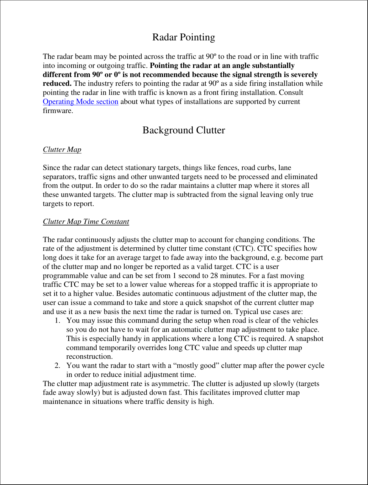


![Houston Radar PD420 User Manual Page 44 of 46 Appendix E: ASCII Interface Some of the radar features can be accessed from ASCII command line interface over the serial port. For example all the radar variables can be set and queried in this fashion. ASCII commands may be issued via an ASCII terminal program like Hyperterminal or Teraterm Pro. Alternatively, you may issue these commands from an attached microcontroller. Notation: [xxx] – optional argument <Cr> - “Enter” key, carriage return character Supported ASCII commands: get - get one or more (up to 6) variables. If domain is not specified, it defaults to 0 (persistent configuration variables). When retrieving multiple variables they all must belong to the same domain. Syntax: get:<name> [<name>]…[<name>] [<domain>] <Cr> Examples: 1. Get a single variable from default domain 0 get:TC returns TC=5 (if value is presently set to 5). 2. Get 6 variables from domain 2 get:C1 C2 C3 C4 C5 C6 2 will get the counts for all 6 lanes. The last argument (2) specifies that you want to read from the volatile domain. You may omit it if you are reading variables from non-volatile domain. set - set a variable to a supplied value Configuration settings are written to FLASH memory and are non-volatile. Do not update settings on a periodic basis, e.g. every second or every minute. Only change settings when the user needs it. The FLASH memory has a limited number of write cycles and will wear out with excessive (>10,000) number of writes. On the other hand, setting the variable to the same value repeatedly is OK because the radar recognizes that the variable has not changed and does not update it in FLASH. Syntax: set:<name> <value> [<domain>]<Cr> Examples: set:LO 5 alternative format: set:LO=5](https://usermanual.wiki/Houston-Radar/PD420/User-Guide-3555469-Page-44.png)