Houston Radar DR1500 Doppler Speed Radar User Manual DR1500 rev1
Houston Radar LLC Doppler Speed Radar DR1500 rev1
UserManual.wiki
>
Houston Radar
>
DR1500 User Manual
User Manual
Navigation menu
Upload a User Manual
Namespaces
Wiki Guide
HTML
PDF
Info
Views
User Manual
Discussion / Help
Navigation
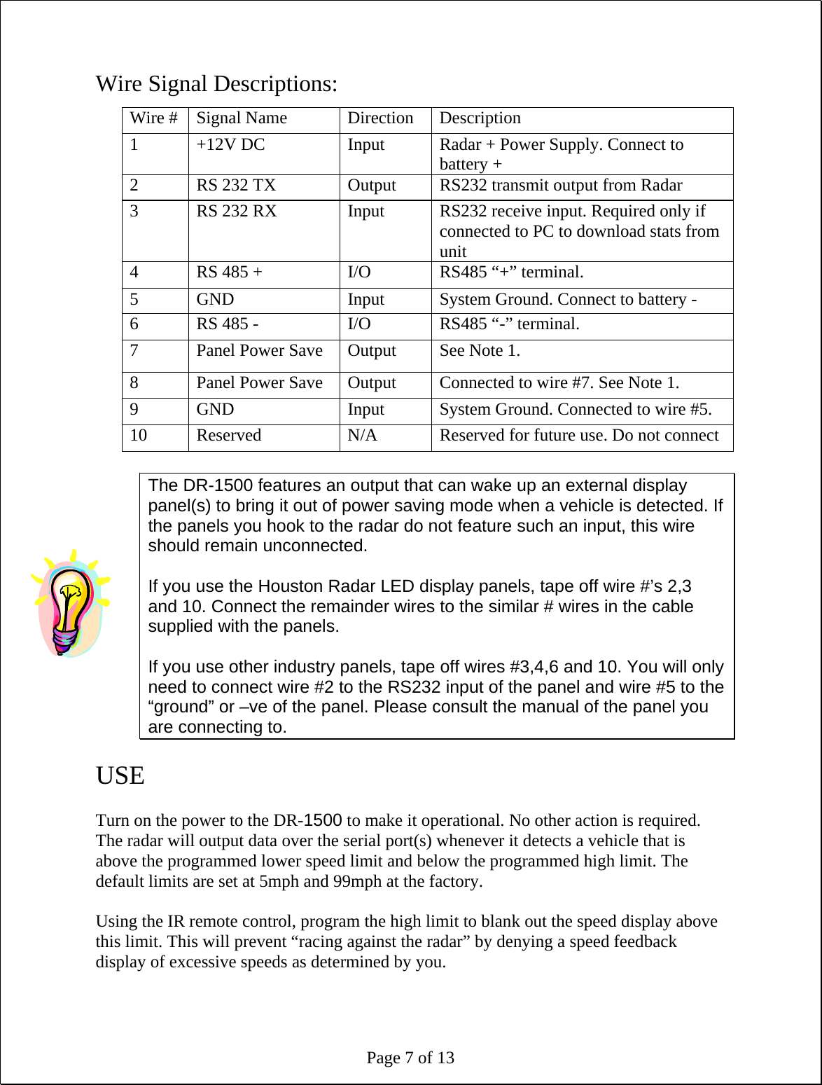
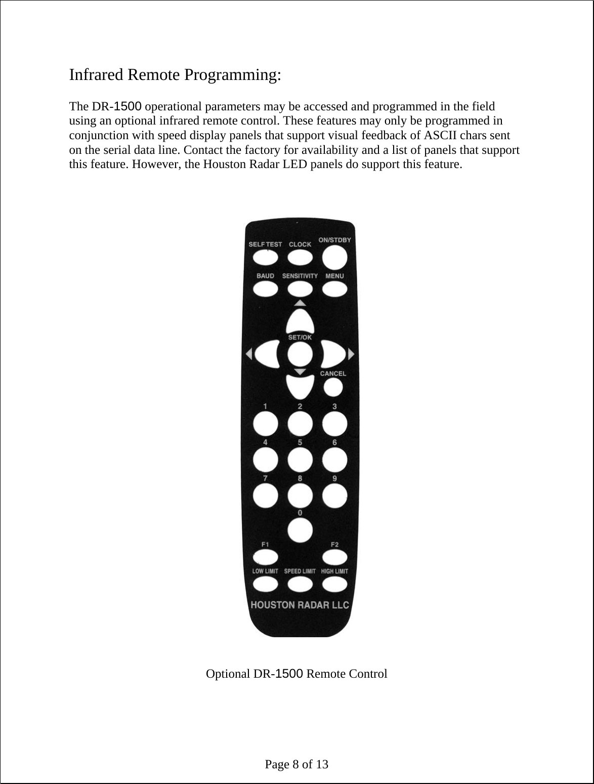
![Page 9 of 13 This section describes these features and how to program the values into the radar using the IR remote. Apply +12 V DC battery power to the radar power wires. Stand in front of the radar, between 2 and 10 feet away and point the IR remote at the front face of the radar (the IR receiver window is the small circular hole below the rectangular window). Then execute the following steps to program the desired functions: Speed Low Limit: Use this feature to only give speed awareness feedback to vehicles over a certain limit, for example the road speed limit. This would setup the system to not display the speeds of vehicles that are below the limit, rather only display the speed of vehicles that are above the limit. With panels that support the “power saving mode”, this can result in very significant power savings and significantly extend operation time between battery recharges. 1. Press the “LOW LIMIT” key once [The current value will be displayed on the display] 2. Enter the numeric speed for the low limit (or use the Up/Down arrow keys) 3. Press “SET/OK” to save the limit in the radar or press “CANCEL” at any time before “SET/OK” to cancel this operation Speed High Limit: Use this feature to blank out the speed display of vehicles over this limit. You can use this feature to defeat “racing against the radar” issue. 1. Press the “HIGH LIMIT” key once [The current value will be displayed on the display] 2. Enter the numeric speed for the high limit (or use the Up/Down arrow keys) 3. Press “SET/OK” to save the limit in the radar or press “CANCEL” at any time before “SET/OK” to cancel this operation Speed Limit: Use this feature to flash the speed display of vehicles over this limit. You can use this feature to draw attention to the speed of vehicles going over the set limit. 1. Press the “SPEED LIMIT” key once [The current value will be displayed on the display] 2. Enter the numeric speed for the speed limit in effect at the current location 3. Press “SET/OK” to save the limit in the radar or press “CANCEL” at any time before “SET/OK” to cancel this operation](https://usermanual.wiki/Houston-Radar/DR1500/User-Guide-920348-Page-9.png)
![Page 10 of 13 Detection Sensitivity: Use this feature to set the detection sensitivity. This affect the distance the radar detects objects. You may set the sensitivity from a value of “10” to “99”. Each value is an approximate percentage of maximum detectable range (typically 500 to 600 feet for the DR-1500). Setting the value to “99” sets the range to maximum. This is due to typically only two display digits being used with the radar. 1. Press the “SENSITIVITY” key on the remote once [The current value will be displayed on the display] 2. Enter the desired sensitivity as a two digit value from 10 to 99 percentage of maximum range of the radar or use the Up/Down arrow keys 3. Press “SET/OK” to save the limit in the radar or press “CANCEL” at any time before “SET/OK” to cancel this operation Internal Clock: Use this feature to set the internal clock of the radar. This is only required if you have purchased the optional statistics collection package. The unit will keep time even with external power removed. It may be more convenient to set the clock of the radar by connecting a serial cable to the radar and using the “Houston Radar Stats Analyzer” program. A button in the program allows you to sync the radar clock with your computer clock. However, the following steps may be used in the field to either check or set the time of the radar 1. Press the “CLOCK” key on the remote [The radar will display “SE”- short for seconds of the current time] 2. Press the “UP” arrow key on the display to move to the minutes option [The radar will display “MI”- short for minutes of the current time] 3. Press the “UP” arrow key on the display to move to the hours options [The radar will display “HO”- short for hours of the current time] 4. Press the “UP” arrow key on the display to move to the day of the month option [The radar will display “DA”- short for day of the current day of the month] 5. Press the “UP” arrow key on the display to move to the month option [The radar will display “MO”- short for month of the current date (January is “1”, December is “12”)] 6. Press the “UP” arrow key on the display to move to the month option [The radar will display “YE”- short for year of the current date (2000 is “00”, 2006 is “06” etc.)] To set any of the above value, navigate to the desired option, then press “SET/OK”. At this point the radar will display the current option. You may then directly enter the desired value for the option and press “SET/OK” again.](https://usermanual.wiki/Houston-Radar/DR1500/User-Guide-920348-Page-10.png)
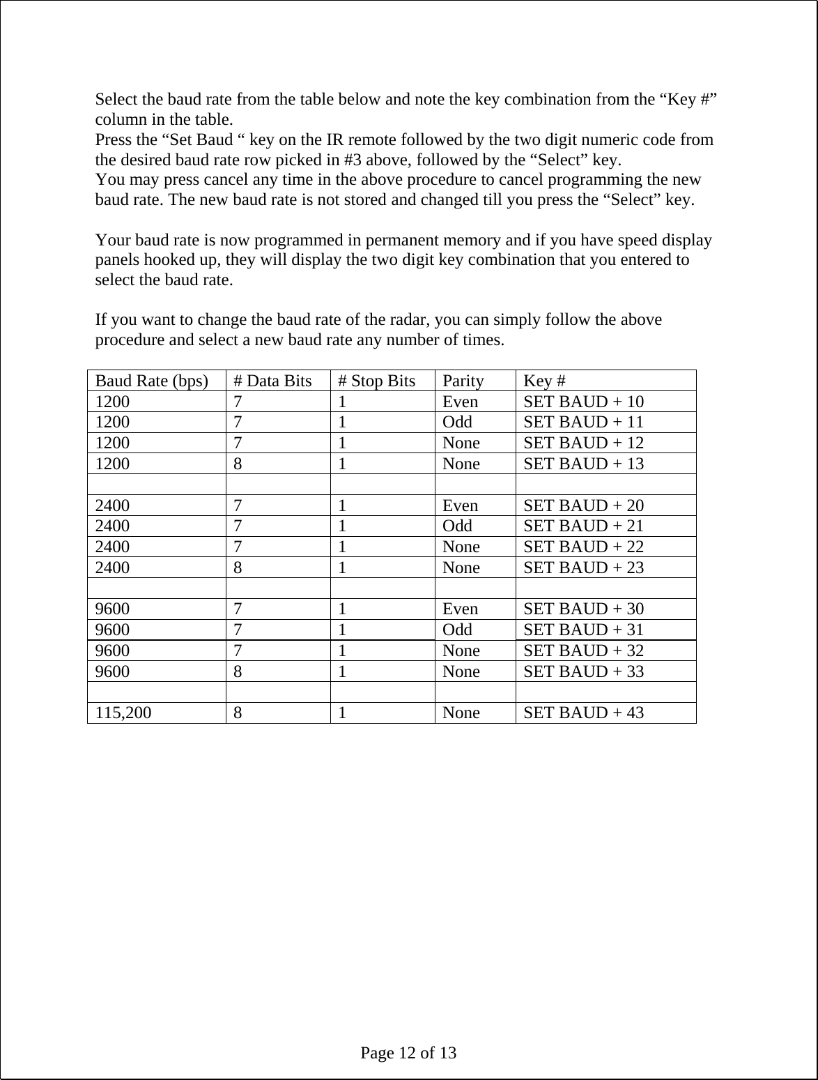
![Page 11 of 13 Press “CANCEL” to at any time or after the final “SET/OK” to exit the menu. Self Test: Press the “SELF TEST” key on the remote to instruct the radar to perform a self test. The radar will display “OK” after about 6 seconds if the test passes. It will then reset and count up from 1 to 9 and then the display will blank out. Display Units (MPH or KMPH): 1. Press the “F1” key on the remote [The radar will display “F1”] 2. Press the “4” key [The radar will display the current value code. 0 = MPH, 1 = KMPH] 3. Press 0 to display speed in MPH or 1 to display speed in KMPH 4. Press “SET/OK” key to save in memory. [Radar will restart and count up from 1 to 9 and the display will go blank. The unit is now ready] Reset Factor Settings: 1. Press the “F1” key on the remote [The radar will display “F1”] 2. Press the “3” key on the remote 3. Press the “SET/OK” [Radar will display “OK” and then restart and count up from 1 to 10 and the display will go blank. This will reset the baud rate to 115200, display units to MPH, low limit to 5mph, high limit to 99mph and speed limit to 99mph]. Set Serial Baud Rate: This configuration is only required at the factory when mating the radar to the selected speed digit display panels. Once configured, the radar keeps the configuration even after power is removed and need not be reconfigured. The optional statistics package can communicate with the PC to download saved statistics at any set baud rate. The baud rate of the radar is automatically detected by the stats package. Use this feature to set the baud rate of the serial data port by following the following steps:](https://usermanual.wiki/Houston-Radar/DR1500/User-Guide-920348-Page-11.png)