Houston Radar DC310 DC310 Field Sensor Module User Manual 8 User Manualx
Houston Radar LLC DC310 Field Sensor Module 8 User Manualx
UserManual.wiki
>
Houston Radar
>
DC310 User Manual
Users Manual
Navigation menu
Upload a User Manual
Namespaces
Wiki Guide
HTML
PDF
Info
Views
User Manual
Discussion / Help
Navigation


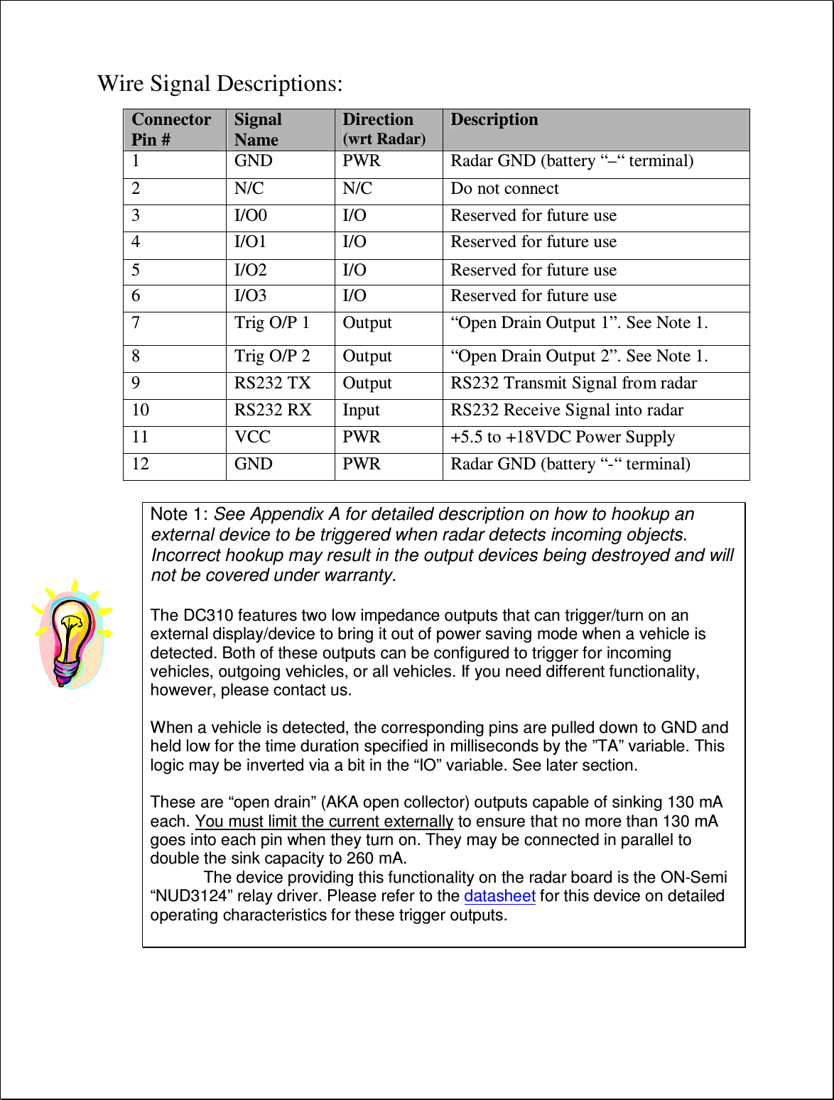
![Hookup: Power Input: The DC310 radar features wide operating input voltage range of 5.5V-18V. In a typical application it may be powered from a nominal 12V DC source and will feature best in class operational power consumption of 14 mA (average). There is no other radar in the world that even comes close to this ultra-low power usage. Competing products may consume up to 20 times more power. This ultra-low operational power translates directly into a longer battery life or gives you an option to power the unit from smaller batteries and smaller solar panels. Note: The radar employs aggressive power saving measures that include turning off parts of the circuit that are not being used at any instant. To get a true measure of the power usage of the circuit use a multi-meter that has an averaging function and does not suffer from autoranging during measurements. Otherwise you will get current readings that fluctuate from 7 mA to 23 mA. Note: when the under-voltage lockout (UVL) feature is activated, the operating voltage range is reduced to 6.2V-18V and dropping the input voltage to 4.5V-6.2V will put the radar into a sleep mode where it will only update the internal clock. Your power supply to the radar must be capable of supplying up to 40mA of current for up to 5 seconds at a time (startup current is higher as the radar is initializing its internal systems). Serial Connection: The DC310 features an RS232 interface that is used to output average speed, access statistics data and configure the unit as explained later in this document. The RS232 interface is factory set to default to “cable detect” mode and will power the interface chip down to save power if the radar RX line is not connected. Cable detect mode may be disabled and the interface may be forced ON via a bit in the “MD” variable. Average Speed Output: The DC310 can send out the average measured speed via the ASCII interface as a 3 digit speed with an optional direction indicator. This option is not turned on in the default configuration, and must be enabled. The format is: [?,+,-]nnn[.ddd][\r,\n] The format of the speed output can be adjusted to any combination of: “?”: Optional prefix sent when 000 is selected to be sent when no vehicles are detected “+”: Optional prefix sent when nnn speed is sent for incoming vehicles “-”: Optional prefix sent when nnn speed is sent for outgoing vehicles “nnn”: Three digit ASCII speed in the units selected via the UN variable](https://usermanual.wiki/Houston-Radar/DC310/User-Guide-2057090-Page-8.png)
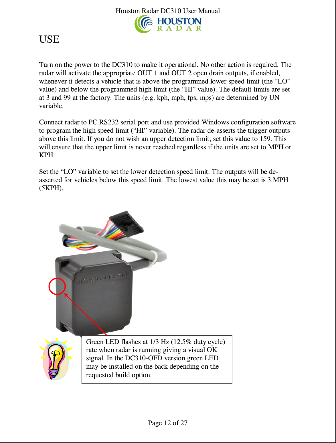
![“.ddd”: Programmable number of digits (0-3) after decimal point “\r”: Carriage Return character, optional line ending “\n”: Line Feed character, optional line ending At least one or both of the line endings must be selected with ASCII format. No line ending is not an option. Please see serial port configuration section for details on how to select the above format. Setting variables from an ASCII Terminal program via ASCII commands: All the radar variables can be set and queried via a simple ASCII command set over the serial port. ASCII commands may be issued via an ASCII terminal program like Hyperterminal or Teraterm Pro. Alternatively, you may issue these commands from an attached microcontroller. All settings are written to FLASH memory and are non-volatile. Do not update settings on a periodic basis, e.g. every second or every minute. Only change settings when the user needs it. The FLASH memory has a limited number of write cycles and will wear out with excessive (>10,000) number of writes. On the other hand, setting the variable to the same value repeatedly is OK because the radar recognizes that the variable has not changed and does not update it in FLASH. The ASCII commands are: get (get a config variable) set (set a config variable to a supplied value) reset (resets the radar. Required after changing variables MO, MD and RS). info (print out some info about the radar. Info is in the format of <tag>=<value>). New tags may be added in the future. Order of tags may be moved around. e.g. To set a variable (variables are documented in the user manual): set: <case sensitive var name> <value>[Enter] e.g. set:LO 5 alt format: set:LO=5 sets the low speed cutoff to 5 etc. Variables are case sensitive. Commands are not. Success is indicated by an "OK". Failure is indicated by either: "ERROR" - Command was recognized but some other error occurred (variable not present, format not correct, etc.) <nothing returned> - Command was not recognized. Entire line was silently discarded. This ensures that spurious things like enters or other ASCII chars do not generate](https://usermanual.wiki/Houston-Radar/DC310/User-Guide-2057090-Page-9.png)
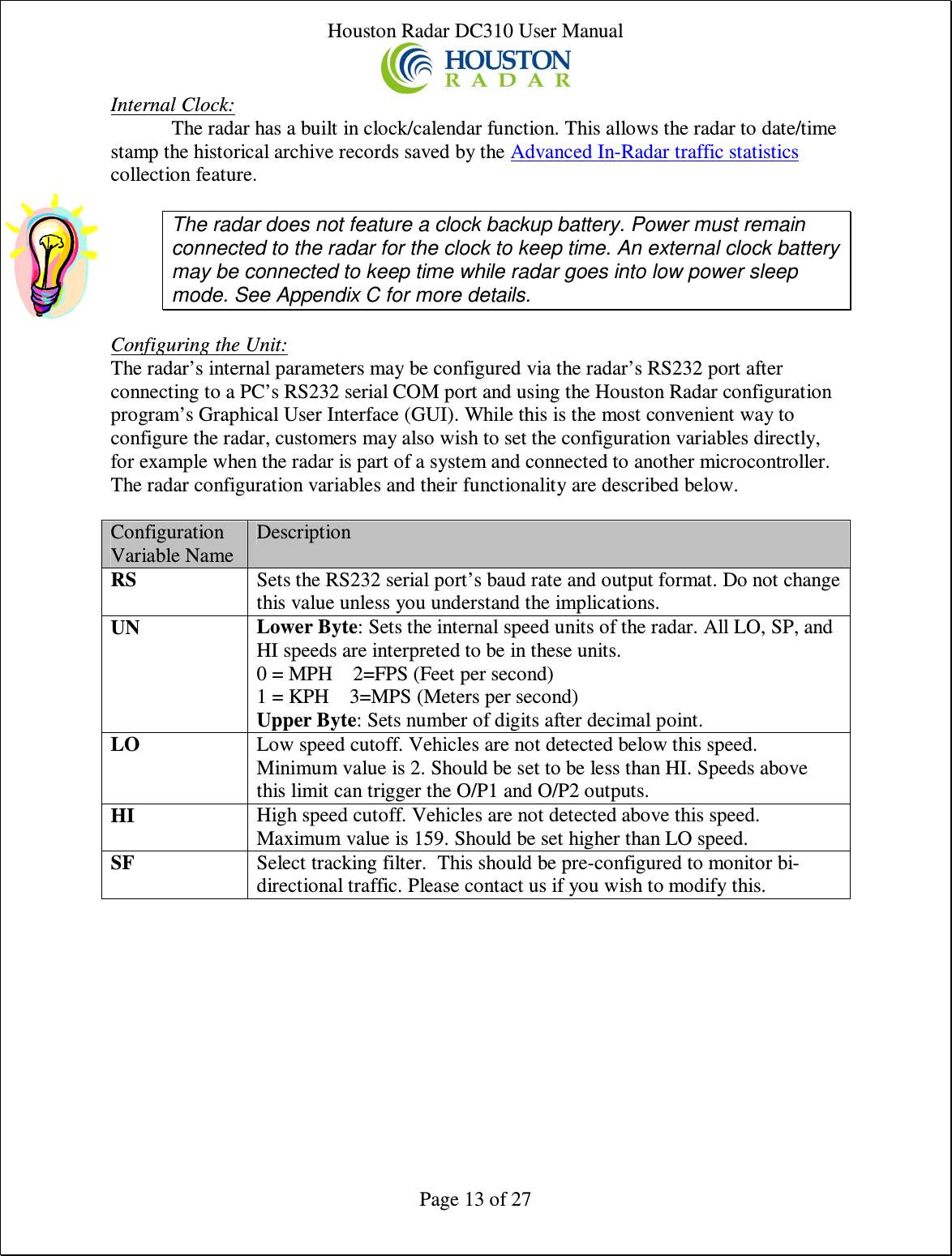
!["ERROR" when you are not expecting them. To get a variable: get:<case sensitive var name>[ENTER] e.g. get:LO returns LO=5 (if value is presently set to 5). If sending the ASCII command via an attached microcontroller, the “[ENTER]” key press should be replaced by the carriage return and/or line feed ASCII character.](https://usermanual.wiki/Houston-Radar/DC310/User-Guide-2057090-Page-10.png)