High Flying Electronics Technology HF-SH01 WiFi Module User Manual Manual
High-Flying Electronics Technology Co., Ltd. WiFi Module Manual
UserManual.wiki
>
High Flying Electronics Technology
>
HF-SH01 User Manual
>
Manual
Contents
1.
Addendum
2.
Manual
Manual
Navigation menu
Upload a User Manual
Namespaces
Wiki Guide
HTML
PDF
Info
Views
User Manual
Discussion / Help
Navigation
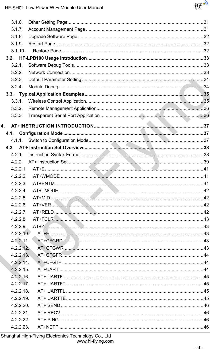
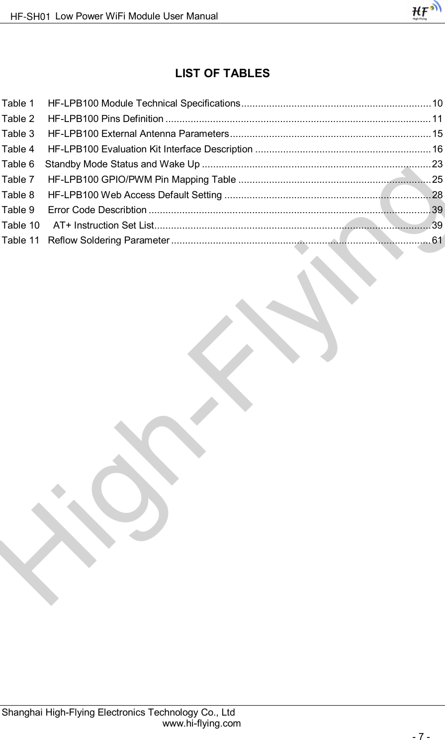
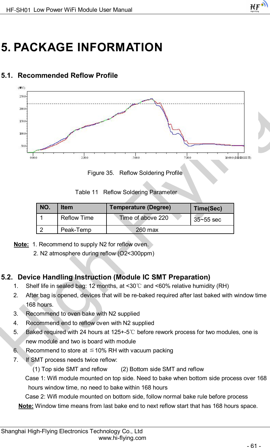
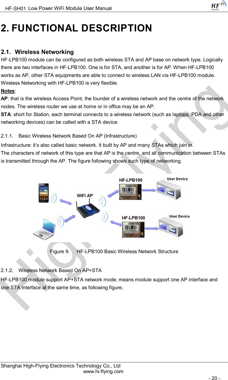
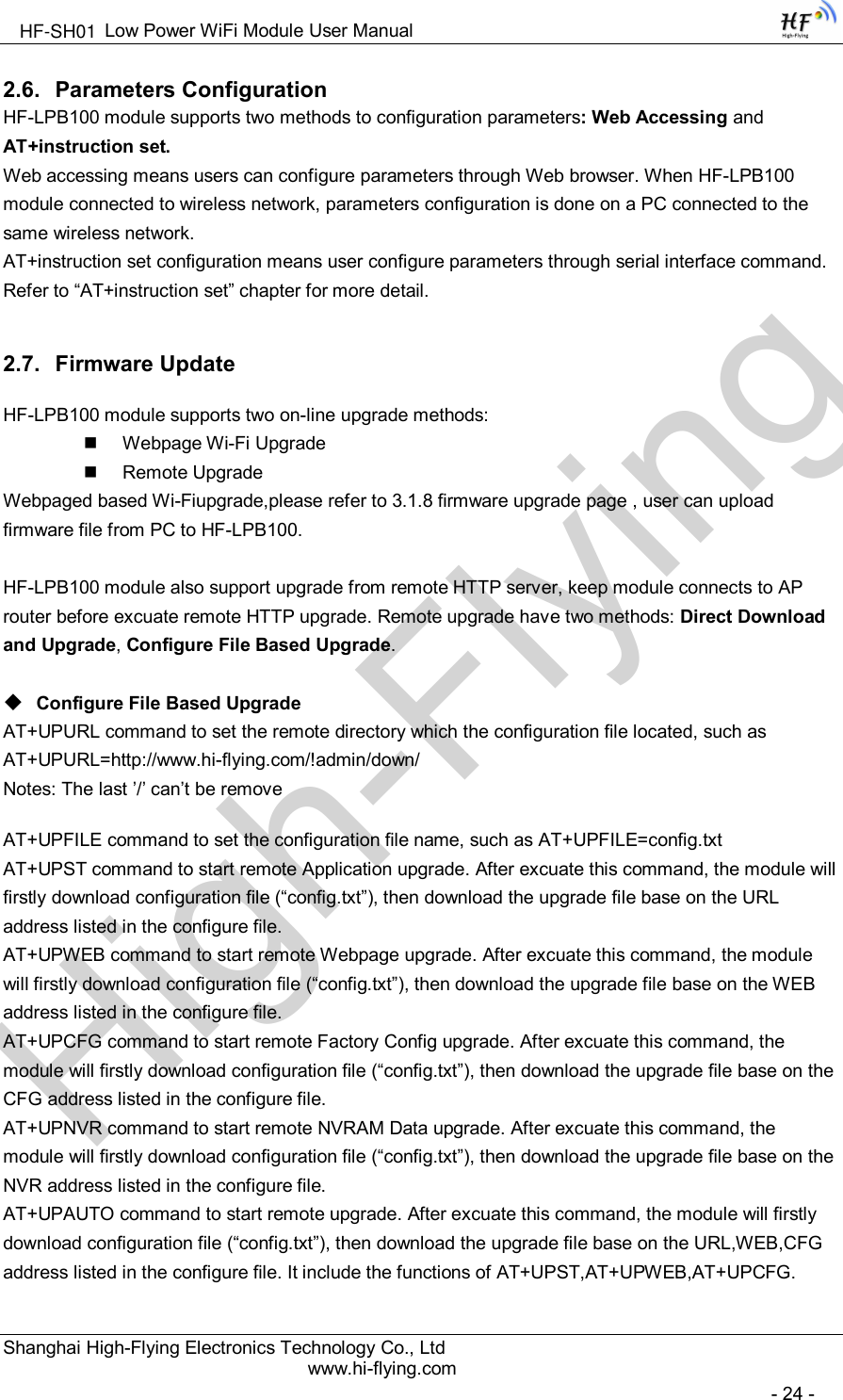
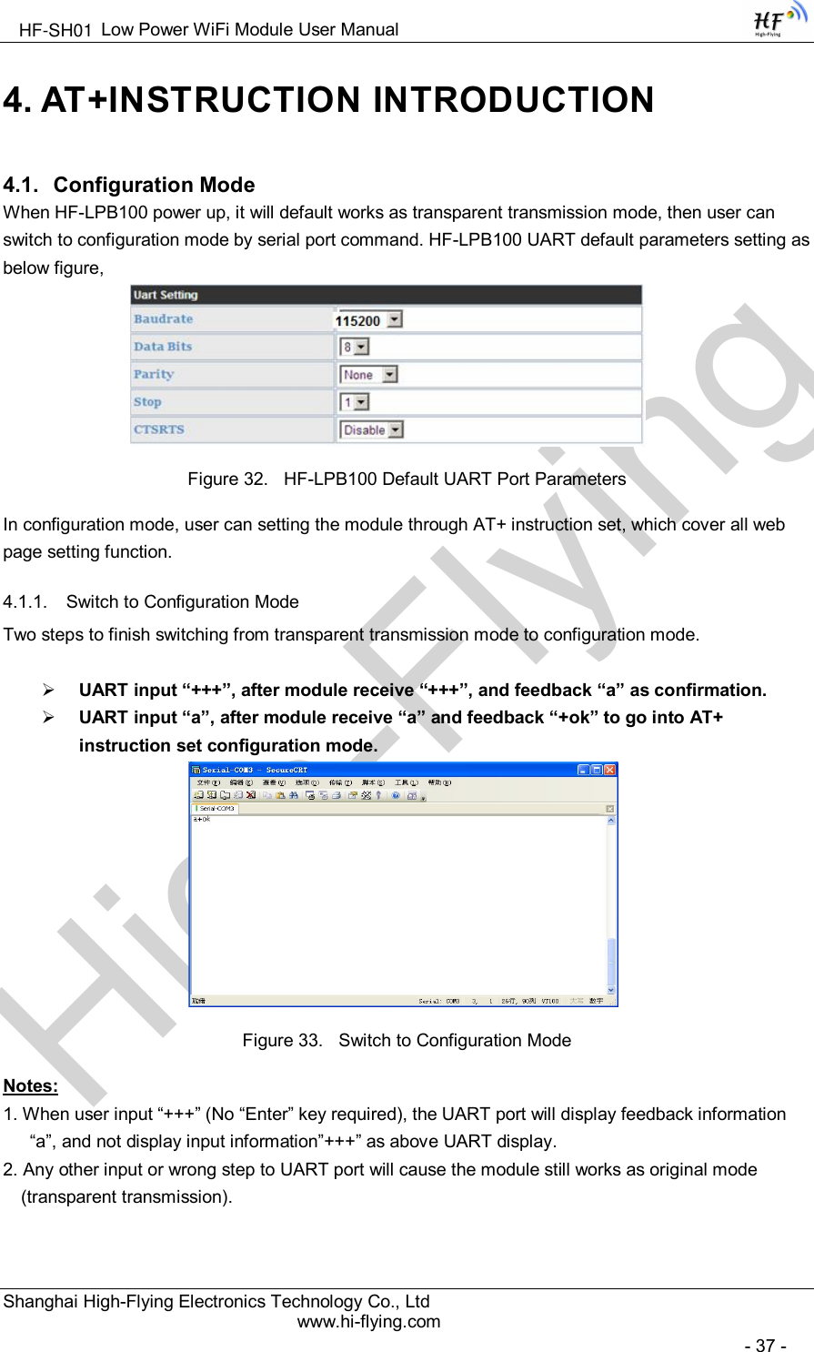
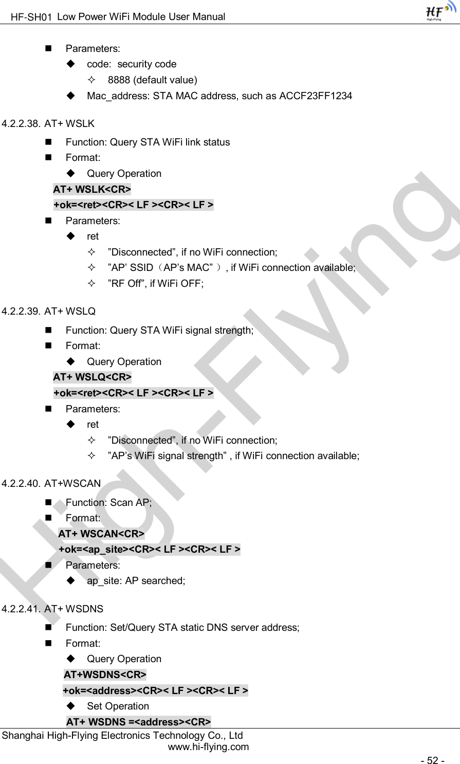
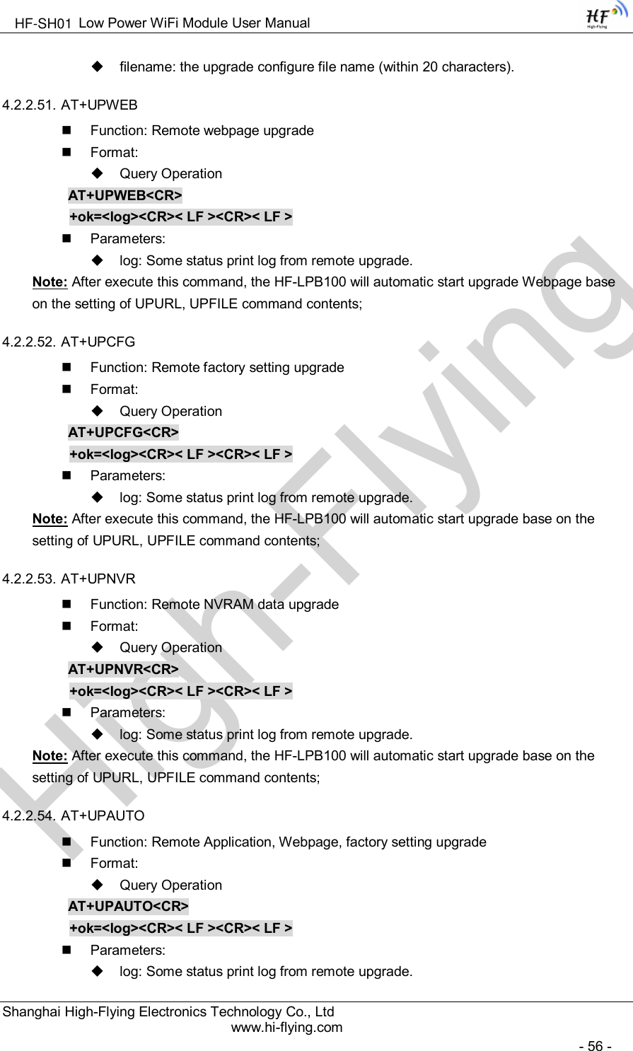
![High-FlyingLow Power WiFi Module User ManualShanghai High-Flying Electronics Technology Co., Ltdwww.hi-flying.com- 10 -1.1.2 Device ParemetersTable 1 HF-LPB100 Module Technical SpecificationsClass Item ParametersWirelessParametersCertification FCC/CEWireless standard 802.11 b/g/nFrequency range 2.412GHz-2.484GHzTransmit Power802.11b: +16 +/-2dBm (@11Mbps)802.11g: +14 +/-2dBm (@54Mbps)802.11n: +13 +/-2dBm (@HT20, MCS7)Receiver Sensitivity802.11b: -93 dBm (@11Mbps ,CCK)802.11g: -85 dBm (@54Mbps, OFDM)802.11n: -82 dBm (@HT20, MCS7)Antenna Option External:I-PEX ConnectorInternal:On-board PCB antennaHardwareParametersData Interface UARTSPI, PWM, GPIOOperating Voltage 2.8~3.6VOperating CurrentPeak [Continuous TX]: ~200mANormal [WiFi ON/OFF, DTIM=100ms]:Average. ~12mA, Peak: 200mAStandby [WiFi Shutdown]: <200uAPower Down Switch: <10uAOperating Temp. -40℃- 85℃Storage Temp. -45℃- 125℃Dimensions and Size 23.1mm×32.8mm×2.7mmSoftwareParametersNetwork Type STA /AP/STA+APSecurity Mechanisms WEP/WPA-PSK/WPA2-PSKEncryption WEP64/WEP128/TKIP/AESUpdate Firmware Local Wireless, RemoteCustomization Web Page UpgradeSupport SDK for application developNetwork Protocol IPv4, TCP/UDP/FTP/HTTPUser Configuration AT+instruction set. Android/ iOSSmart Link APP tools1.1.3 Key ApplicationRemote equipment monitoringAsset tracking and telemetrySecurityIndustrial sensors and controlsHome automationMedical devicesHF-SH01](https://usermanual.wiki/High-Flying-Electronics-Technology/HF-SH01.Manual/User-Guide-2604096-Page-10.png)
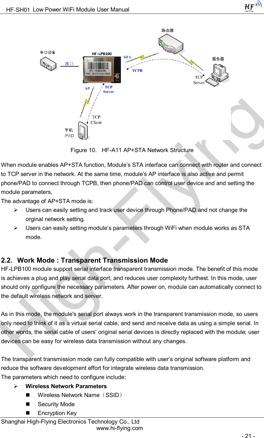
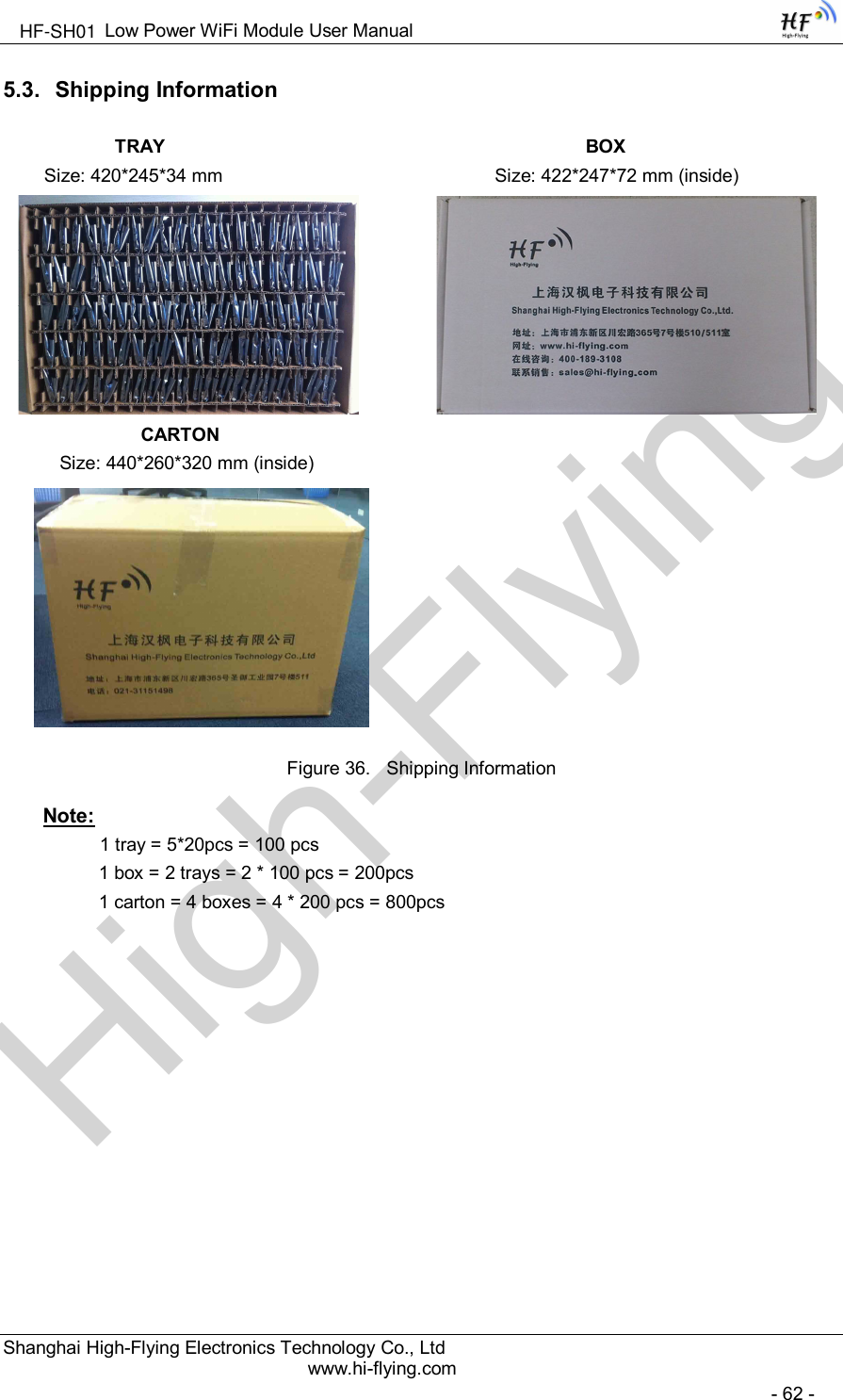
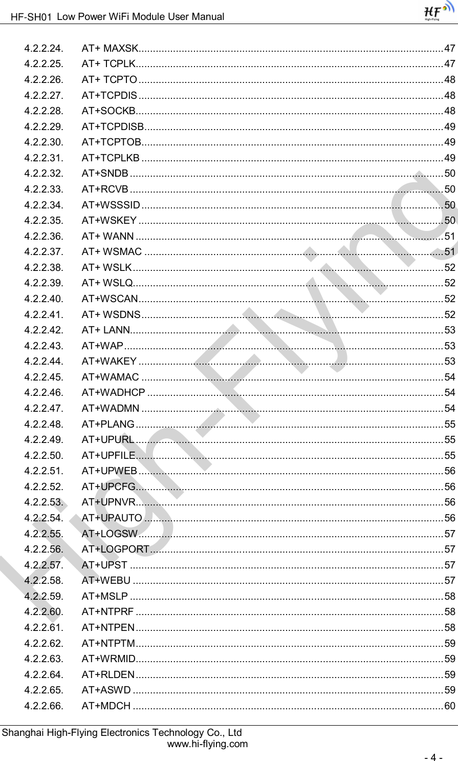
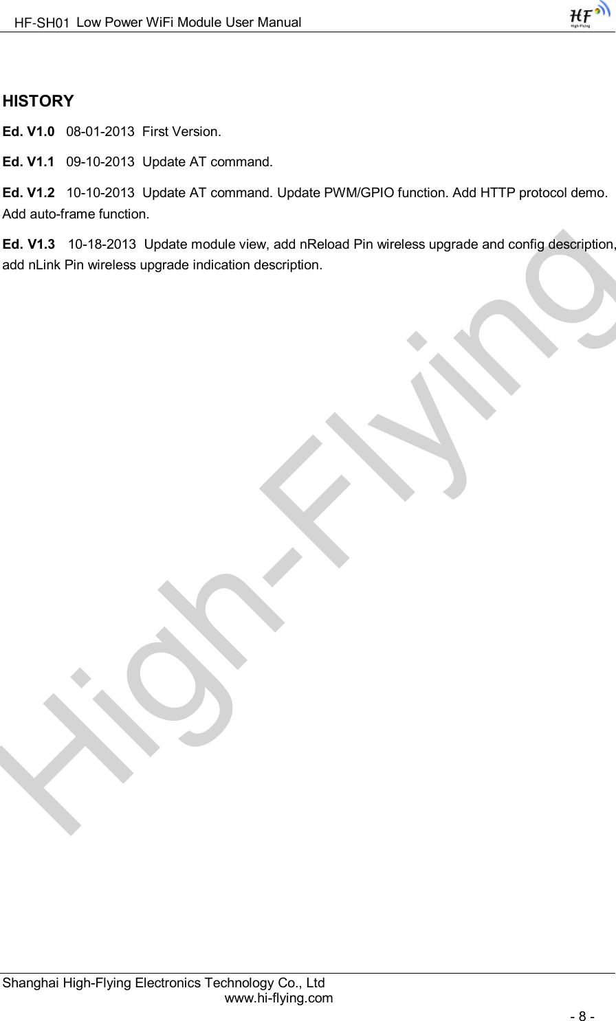
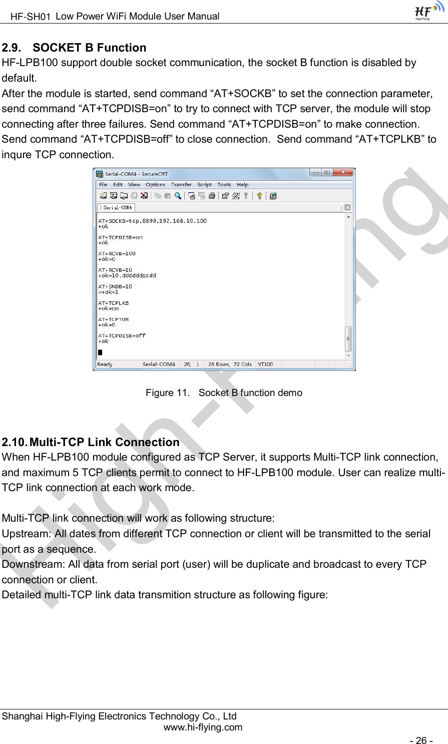
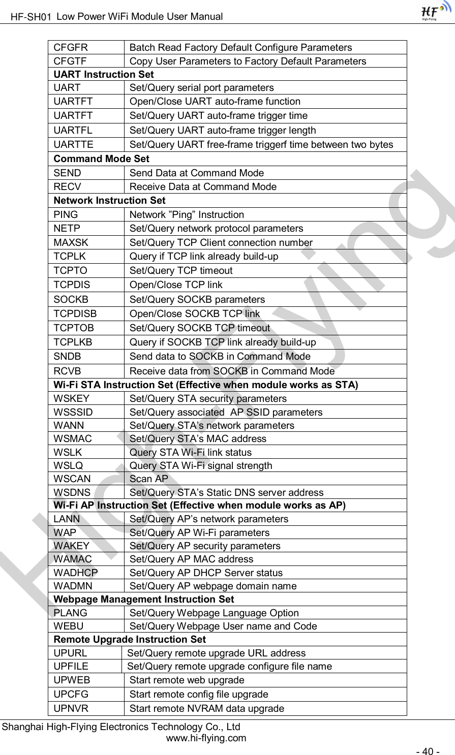
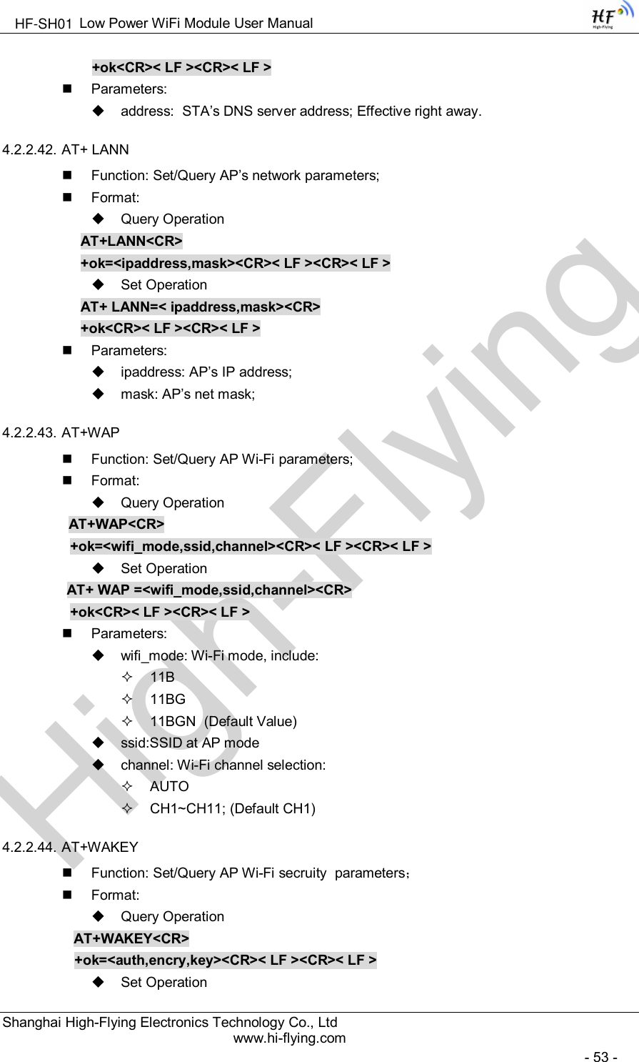
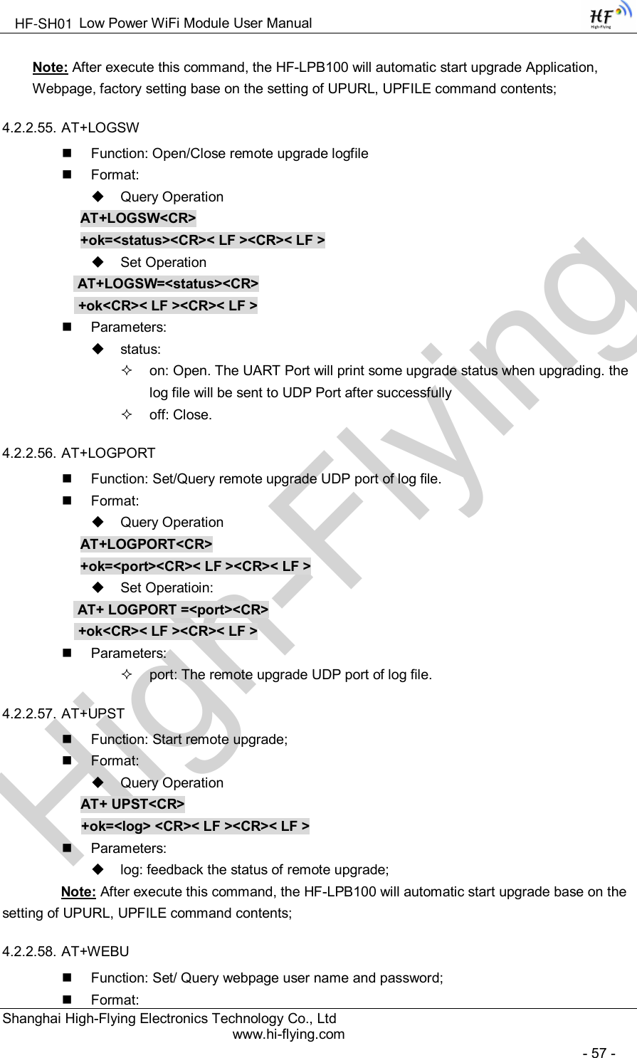
![High-FlyingLow Power WiFi Module User ManualShanghai High-Flying Electronics Technology Co., Ltdwww.hi-flying.com- 25 -General “config.txt” file format as following example:[URL]=”http://10.10.100.100:80/lpb.bin”[WEB]="http://10.10.100.100:80/web.bin"[NVR]="http://10.10.100.100:80/nvram.dat"[CFG]= "http://10.10.100.100:80/cfg.bin"[URL]= the URL address of Application.[WEB]=the URL address of Webpage[NVR]= the URL address of NVRAM data[CFG]= the URL address of Factory Parameter FileDirect Download and UpgradeAT+UPURL command to set the remote directory and file name, such as:AT+UPURL=http://www.hi-flying.com/!admin/down/,lpb.binAfter excuate this command, the module will directly download the “lpb.bin” file from remote directoryand start upgrade Application.Notes: please contact with high-flying technical people before upgrade firmware, or maybe damagethe module and can’t work again.2.8. GPIO/PWM FunctionHF-LPB100 module can provide many GPIOs, which include max 6 PWM/GPIO control pins. User devices can read/write GPIO/PWM pins status.Table 7 HF-LPB100 GPIO/PWM Pin Mapping TableWhen module works at PWM mode, PC and other devices can setup connection (TCP/UDP) throughWiFi, then read/write GPIO/PWM information through command data.GPIO n OUT 0, Set GPIOn as output and output ‘0’, Response GPIO OK or GPIO NOK;GPIO n OUT 1, Set GPIOn as output and output ‘1’, Response GPIO OK or GPIO NOK;GPIO n GET, Read GPIOn pin status, Response +ok=1 or GPIO NOKGPIO n SET, Save GPIOn set, Response GPIO OK or GPIO NOKPWM n frequency duty, Set PWMn Channel output, Response GPIO OK or GPIO NOKPWM n GET, Read PWMn Channel set, Response +ok=frequency duty or PWM NOKPWM n SET, Save PWMn Channel set, Response PWM OK or PWM NOKNotes: Please refer to Appendix B for details to use GPIO/PWM.GPIO Configured Function Describtion Default Setting TypeGPIO11 PWM/GPIO Channel PWM_1 GPIO11 I/OGPIO12 PWM/GPIO Channel PWM_2 GPIO12 I/OGPIO15 GPIO Channel GPIO15 GPIO15 I/OGPIO18 PWM/GPIO Channel PWM_3 GPIO18 I/OGPIO20 PWM/GPIO Channel PWM_4 GPIO20 I/OGPIO23 GPIO Channel PWM_5 GPIO23 I/OHF-SH01](https://usermanual.wiki/High-Flying-Electronics-Technology/HF-SH01.Manual/User-Guide-2604096-Page-25.png)
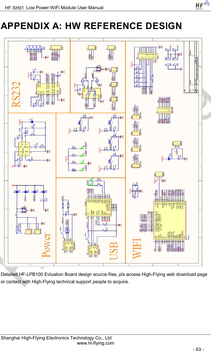
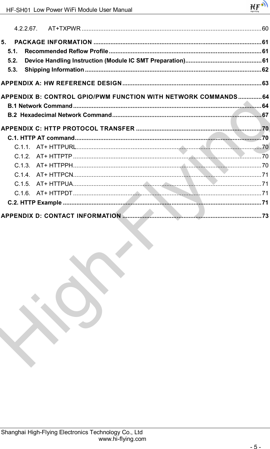
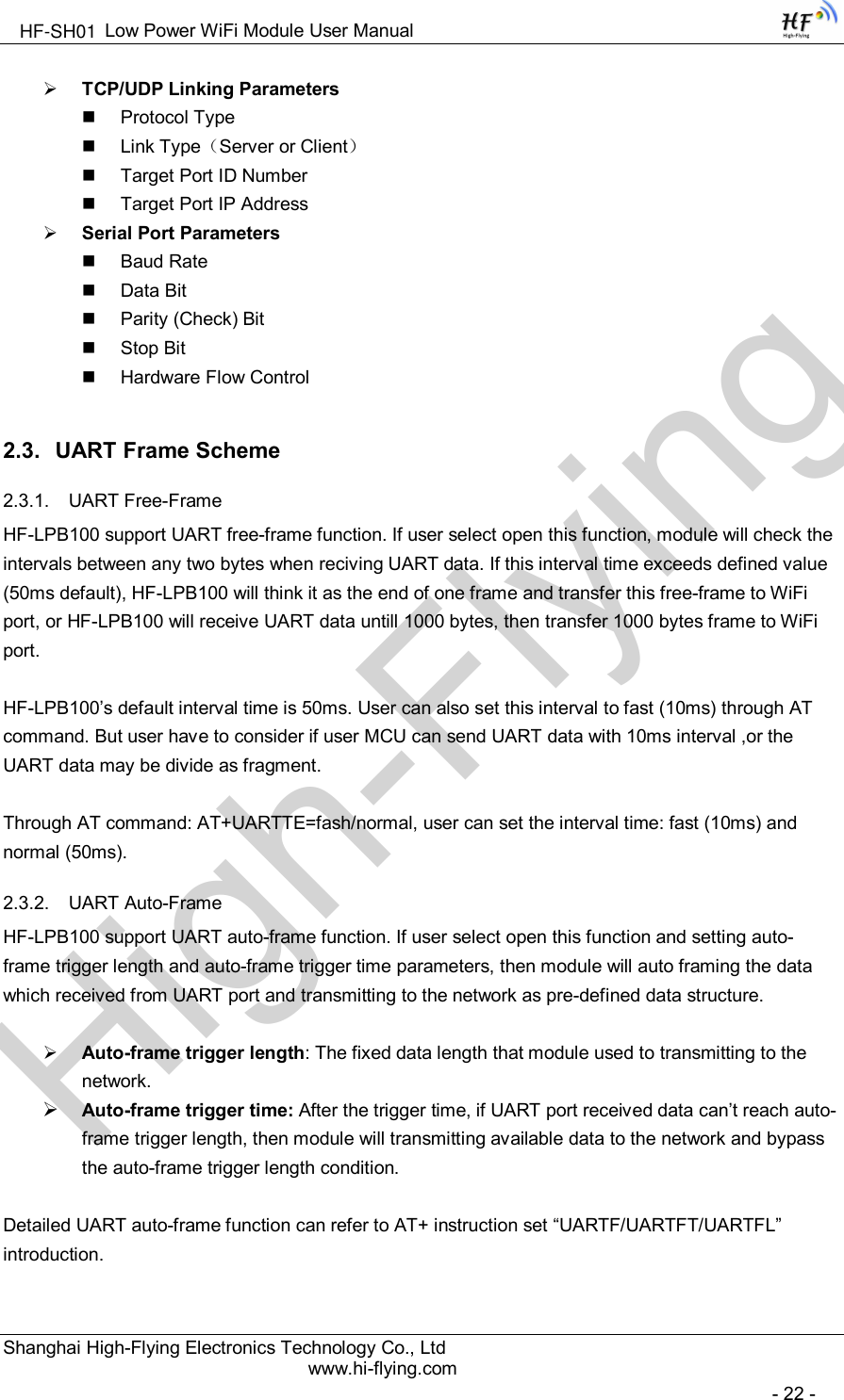
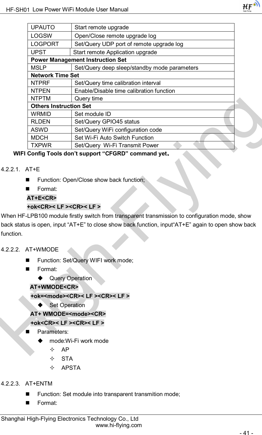
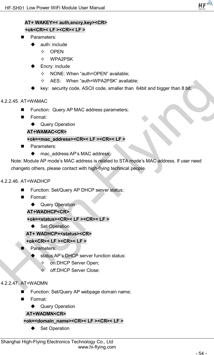
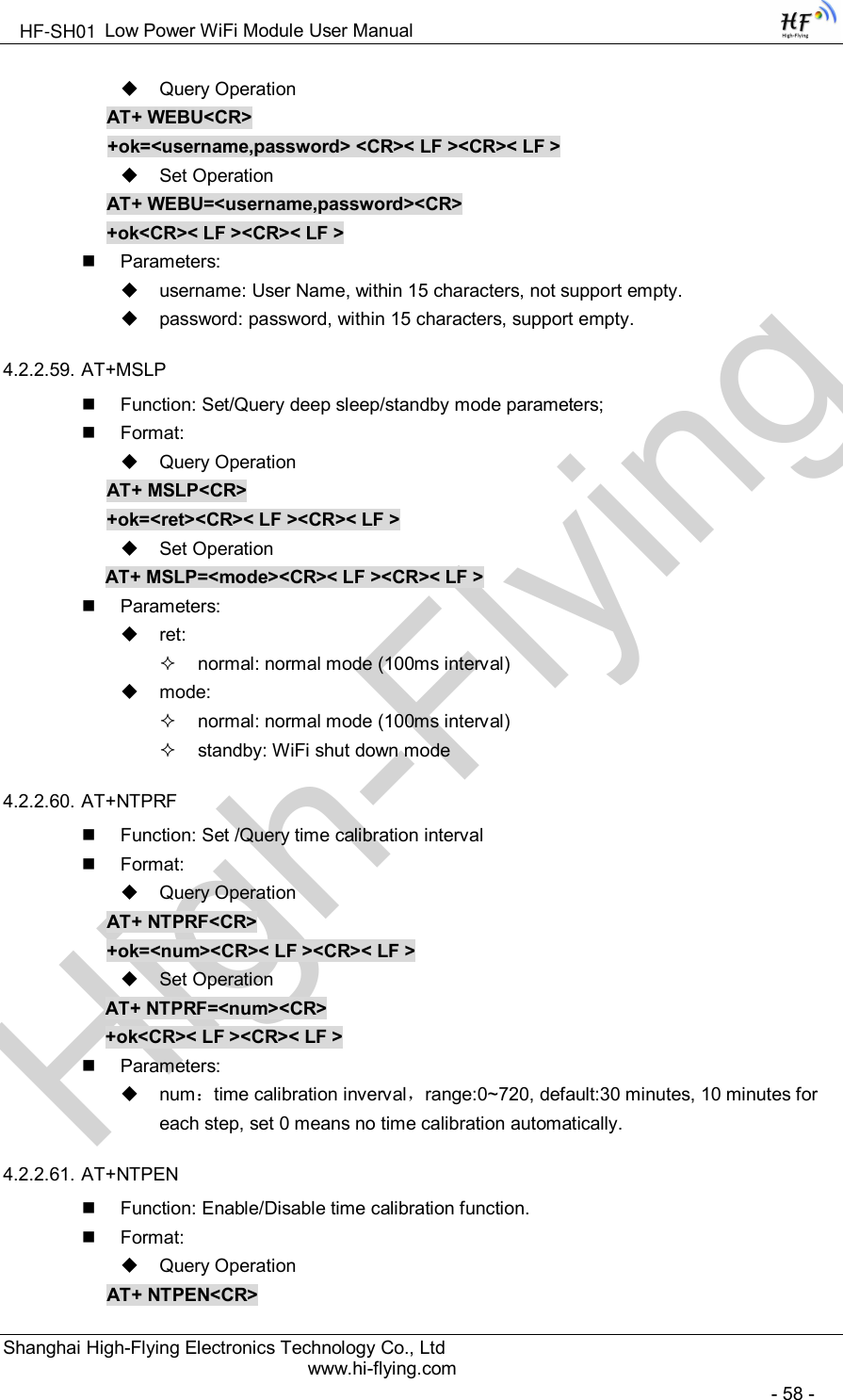
![High-FlyingLow Power WiFi Module User ManualShanghai High-Flying Electronics Technology Co., Ltdwww.hi-flying.com- 38 -AT+ Instruction Set OverviewUser can input AT+ Instruction through hyper terminal or other serial debug terminal, also can program the AT+ Instruction to script. User can also input “AT+H” to list all AT+ Instruction and description tostart.Figure 34. ”AT+H” Instruction for Help4.2.1. Instruction Syntax FormatAT+Instruction protocol is based on the instruction of ASCII command style, the description of syntaxformat as follow.Format Description< >: Means the parts must be included[ ]: Means the optional partCommand MessageAT+<CMD>[op][para-1,para-2,para-3,para-4…]<CR>AT+: Prefix of command message;CMD: Command string;[op]: Symbol of command operator,“=” : The command requires parameters input;“NULL”: Query the current command parameters setting;[para-n]: Parameters input for setting if required;<CR>:”Enter” Key, it’s 0x0a or 0x0d in ASCII;HF-SH01](https://usermanual.wiki/High-Flying-Electronics-Technology/HF-SH01.Manual/User-Guide-2604096-Page-38.png)
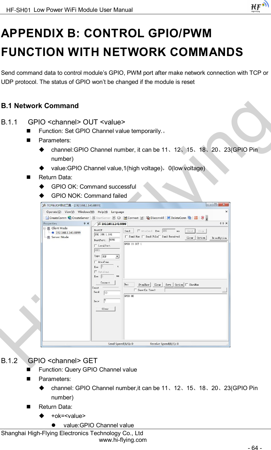
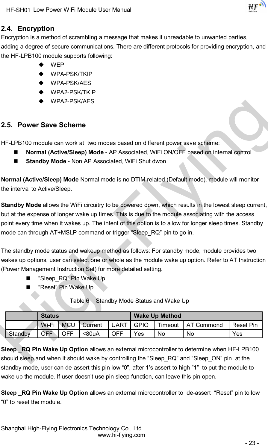
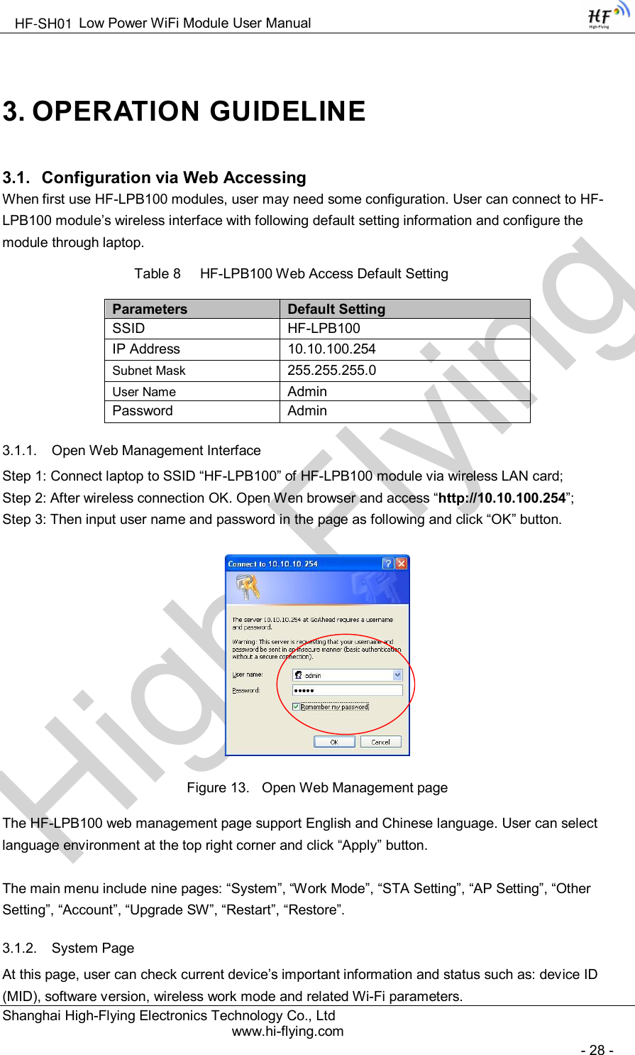
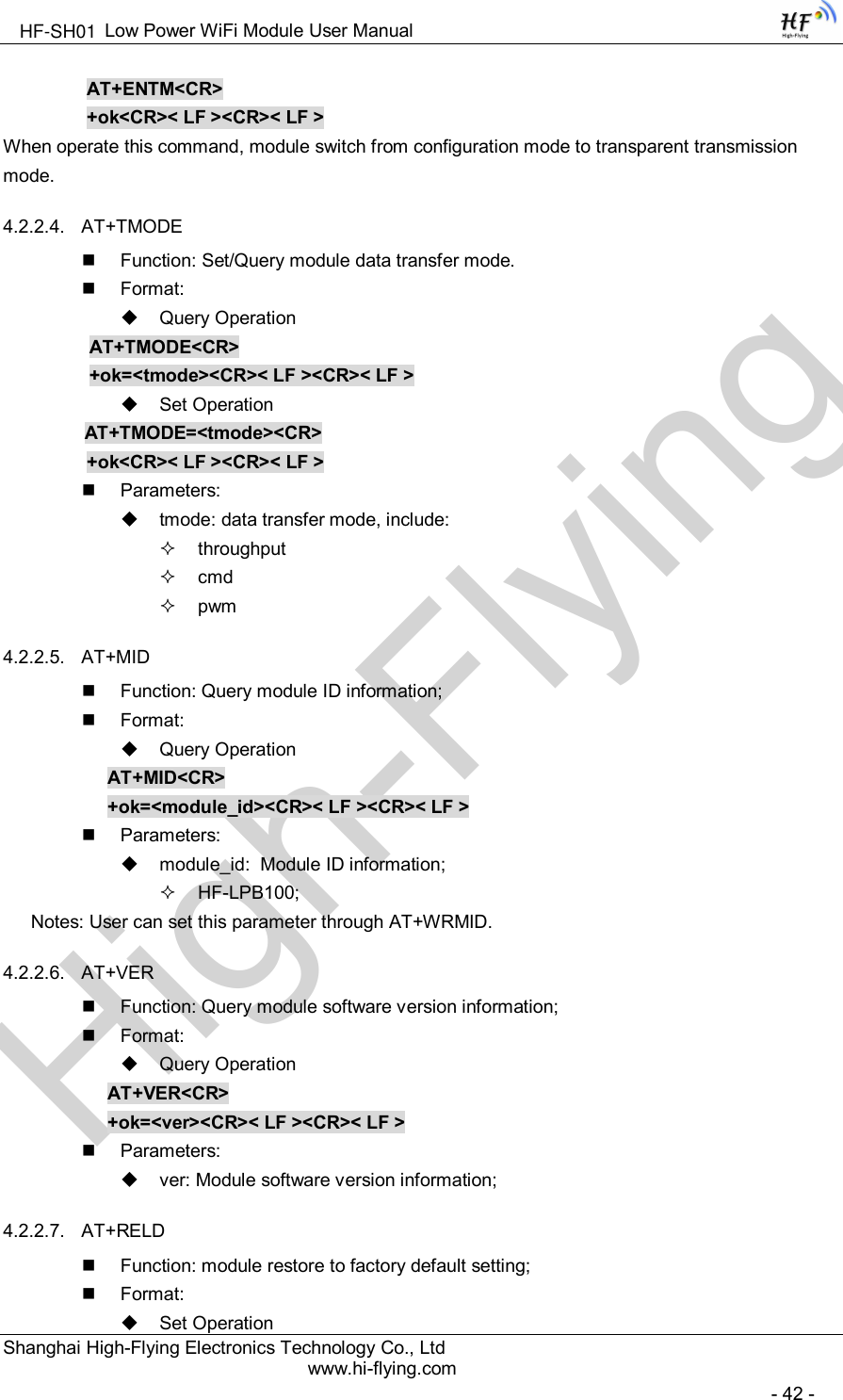
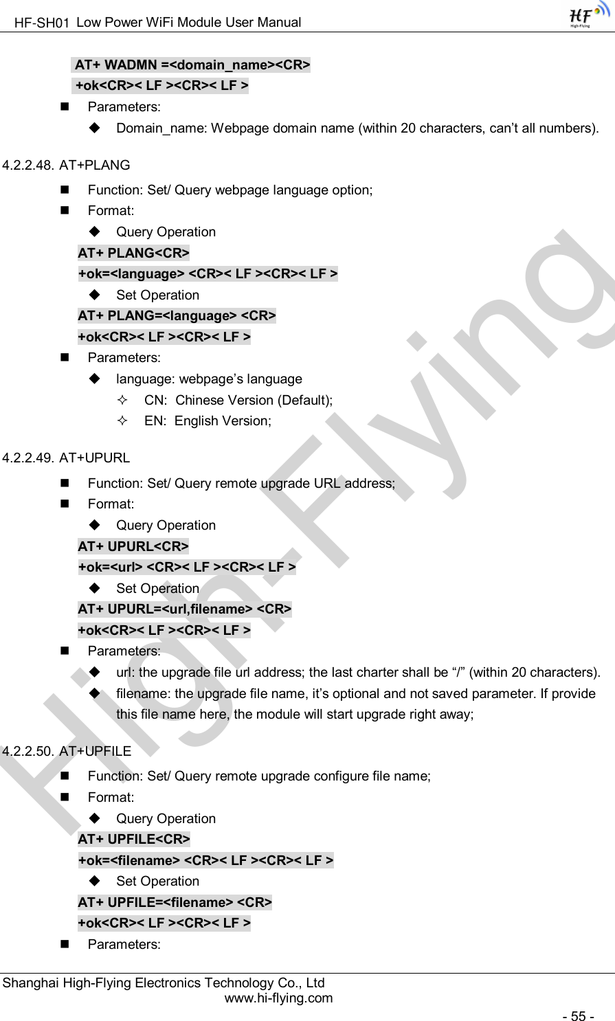
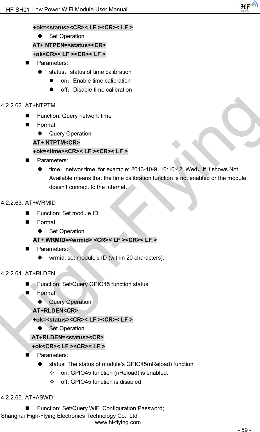
![High-FlyingLow Power WiFi Module User ManualShanghai High-Flying Electronics Technology Co., Ltdwww.hi-flying.com- 39 -Notes: When input AT+Instruction, “AT+<CMD>” character will display capital letter automatic andother parts will not change as you input.Response Message+<RSP>[op] [para-1,para-2,para-3,para-4…]<CR><LF><CR><LF>+: Prefix of response message;RSP: Response string;“ok” : Success“ERR”: Failure[op] : =[para-n]: Parameters if query command or Error code when error happened;<CR>: ASCII 0x0d;<LF>: ASCIII 0x0a;Error CodeTable 9 Error Code DescribtionError Code Description-1 Invalid Command Format-2 Invalid Command-3 Invalid Operation Symbol-4 Invalid Parameter-5 Operation Not Permitted4.2.2. AT+ Instruction SetTable 10 AT+ Instruction Set ListInstruction Description<null> NULLManagment Instruction SetE Open/Close show back functionWMODE Set/Query Wi-Fi work mode (AP/STA/APSTA)ENTM Set module into transparent transition modeTMODE Set/Query module data transfer modeMID Query module ID informationVER Query module software version informationRELD Restore to factory default settingFCLR Erase factory settingZ Re-start moduleH HelpConfigure Parameters Instruction SetCFGRD Batch Read User Configure ParametersCFGWR Batch Write Configure ParametersHF-SH01](https://usermanual.wiki/High-Flying-Electronics-Technology/HF-SH01.Manual/User-Guide-2604096-Page-39.png)

![High-FlyingLow Power WiFi Module User ManualShanghai High-Flying Electronics Technology Co., Ltdwww.hi-flying.com- 60 -Format:Query OperationAT+ ASWD<CR>+ok=<aswd> <CR>< LF ><CR>< LF >Set OperationAT+ ASWD=<aswd> <CR>< LF ><CR>< LF >Parameters:aswd: WiFi Configuration Password (within 20 characters).4.2.2.66. AT+MDCHFunction: Set Wi-Fi Auto Switch FunctionFormat:Query OperationAT+ MDCH<CR>+ok=<mode> <CR>< LF ><CR>< LF >Set OperationAT+ MDCH=<mode> <CR>< LF ><CR>< LF >Parameters:mode: Wi-Fi Auto Switch Modeoff: Disable Wi-Fi auto switch.on: Enable Wi-Fi auto switch. When the module(STA mode) fail to connect torouter, it will switch to AP mode itself in one minute.auto: Enable Wi-Fi auto detect function. The module will reset itself whenencounter any abnormal. The default time interval is 10 minutes.3-120: unit: minute. Set the time interval to reset itself when abnormal.4.2.2.67. AT+TXPWRFunction: Set/Query Wi-Fi Transmit Power, Real Transmit Power=Default TransmitPower(16dBm) – [Setting Value] * 0.5dBmFormat:Query OperationAT+TXPWR <CR>+ok=<num><CR>< LF><CR>< LF>Set OperationAT+TXPWR=<num><CR>+ok<CR>< LF><CR>< LF>Parameters:num: [Setting Value]. The default is 0, it can be sent from 0 ~ 24. If set to 24, themoudule transmit power will be at a minium of 4dBm. Reboot to make this settingchange valid. It will not restore to default if reload the module.HF-SH01](https://usermanual.wiki/High-Flying-Electronics-Technology/HF-SH01.Manual/User-Guide-2604096-Page-60.png)