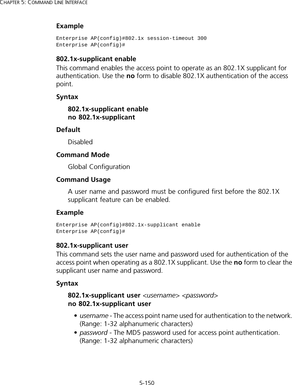
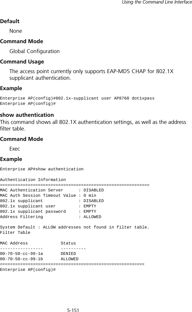
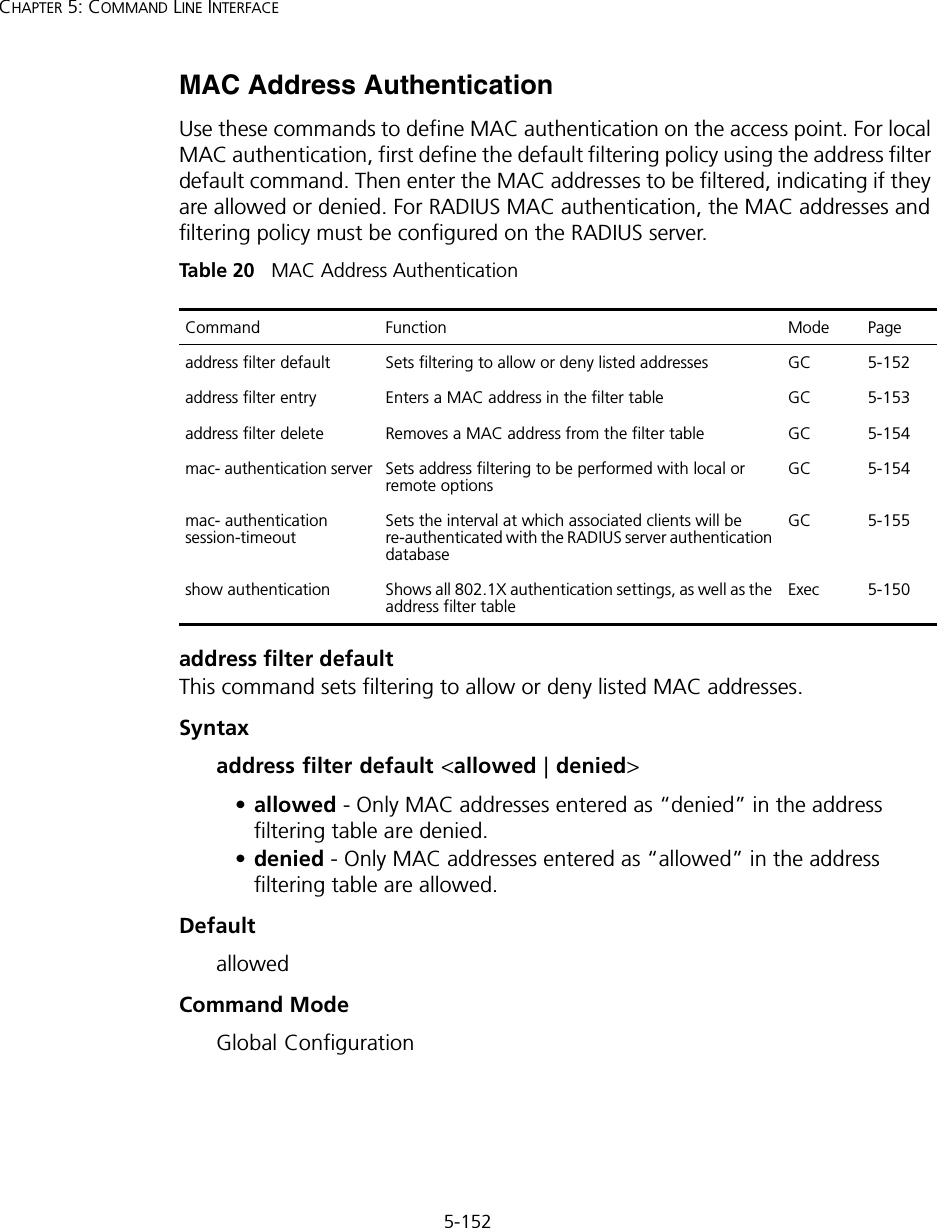
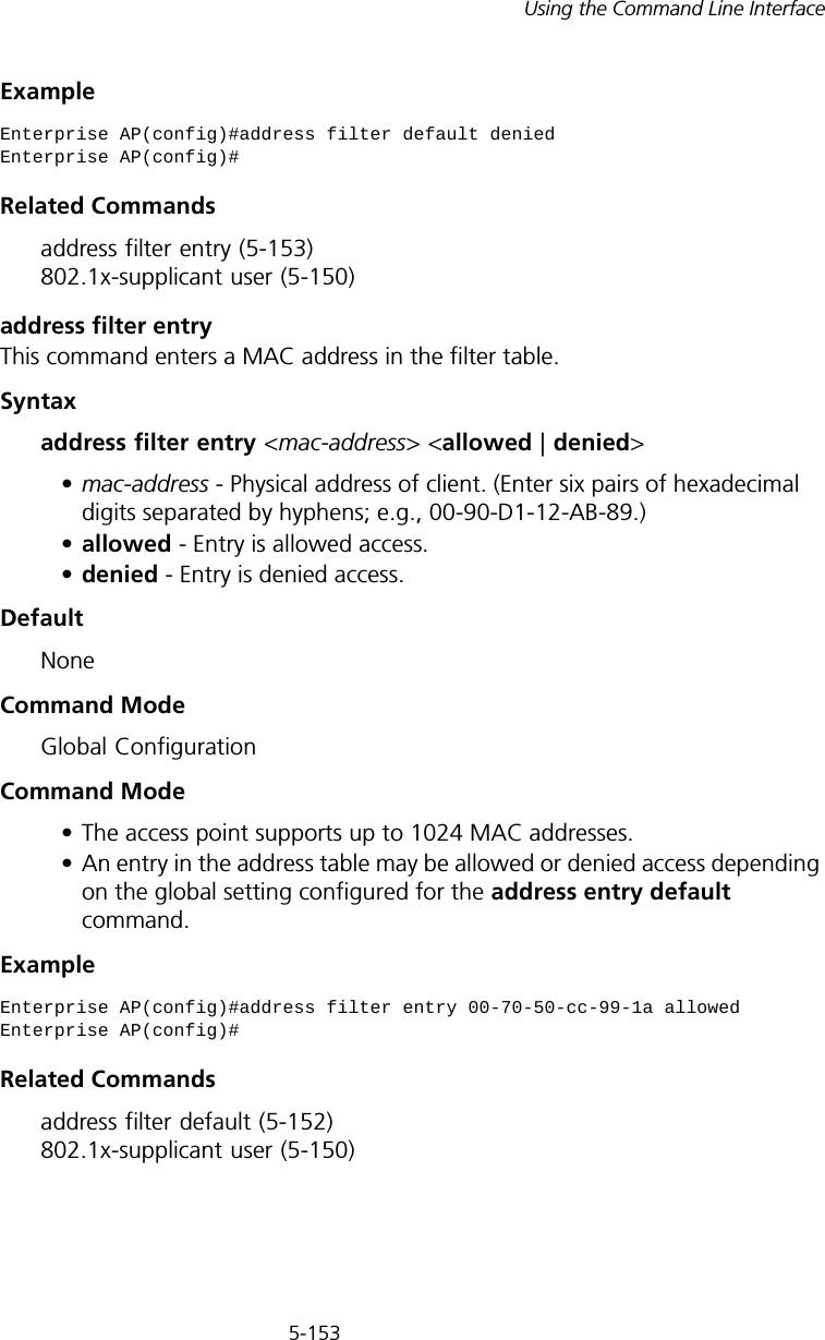
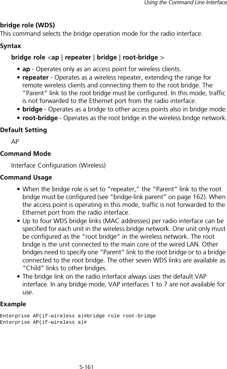
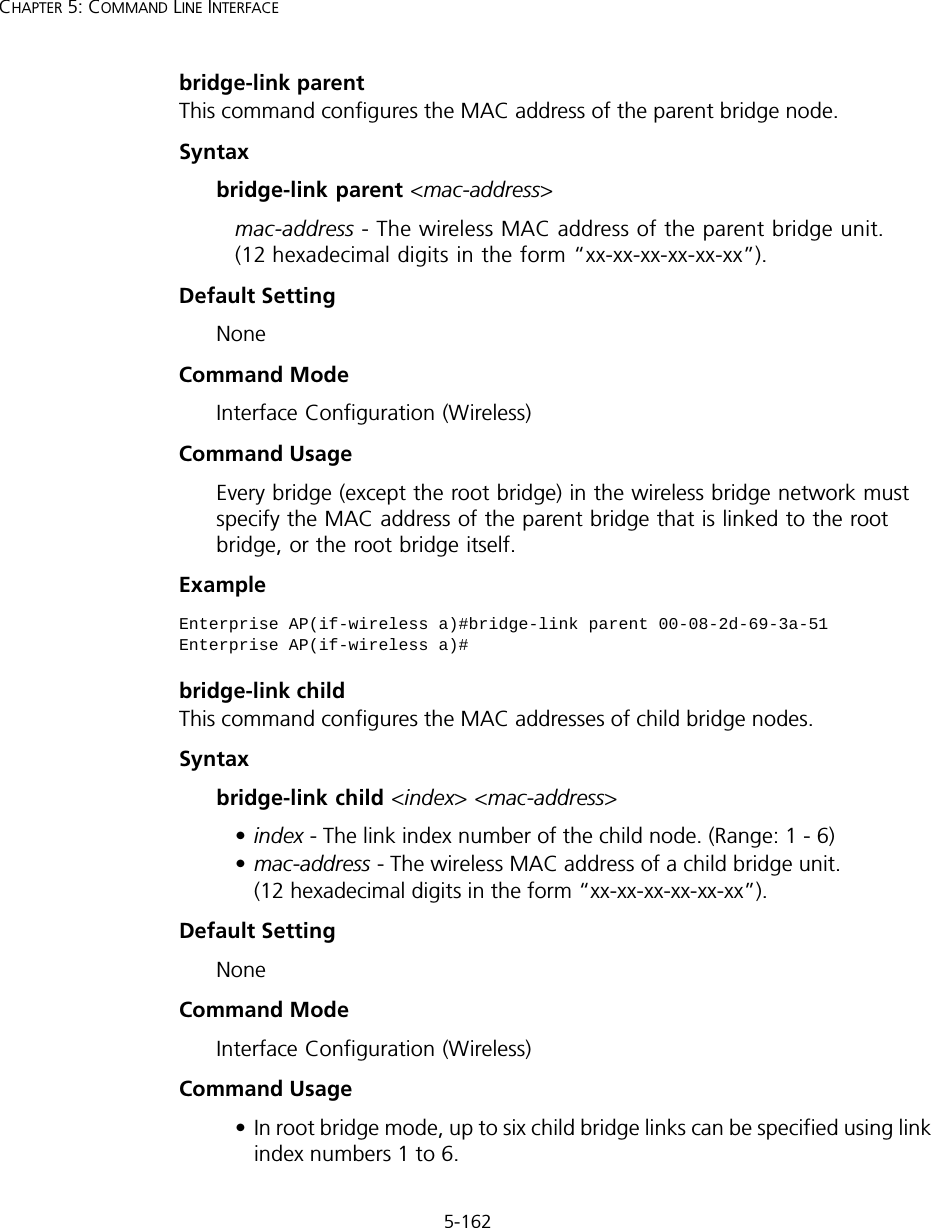
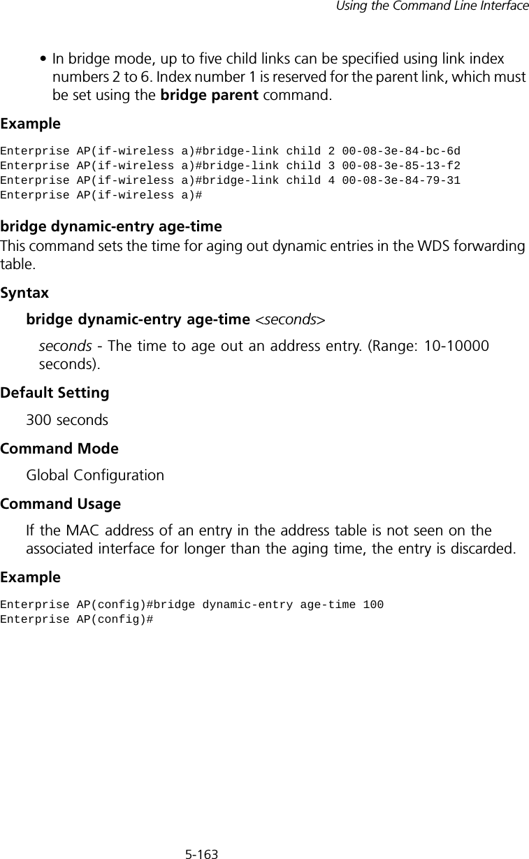
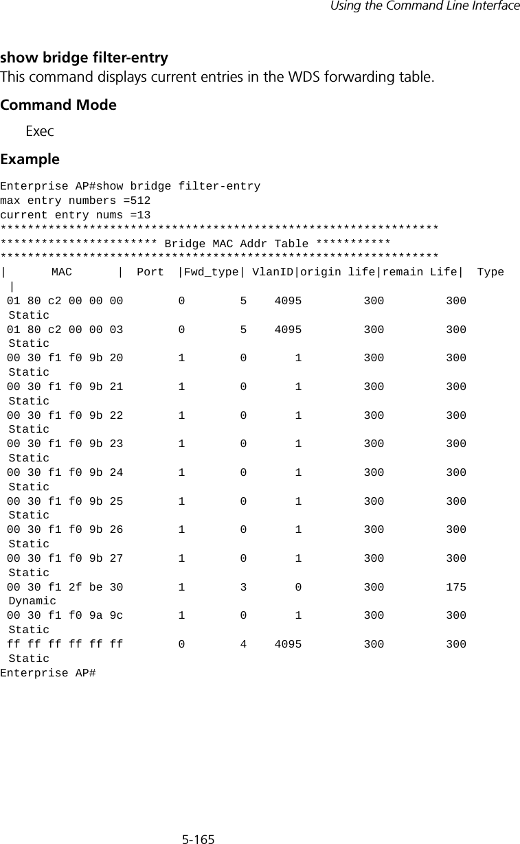
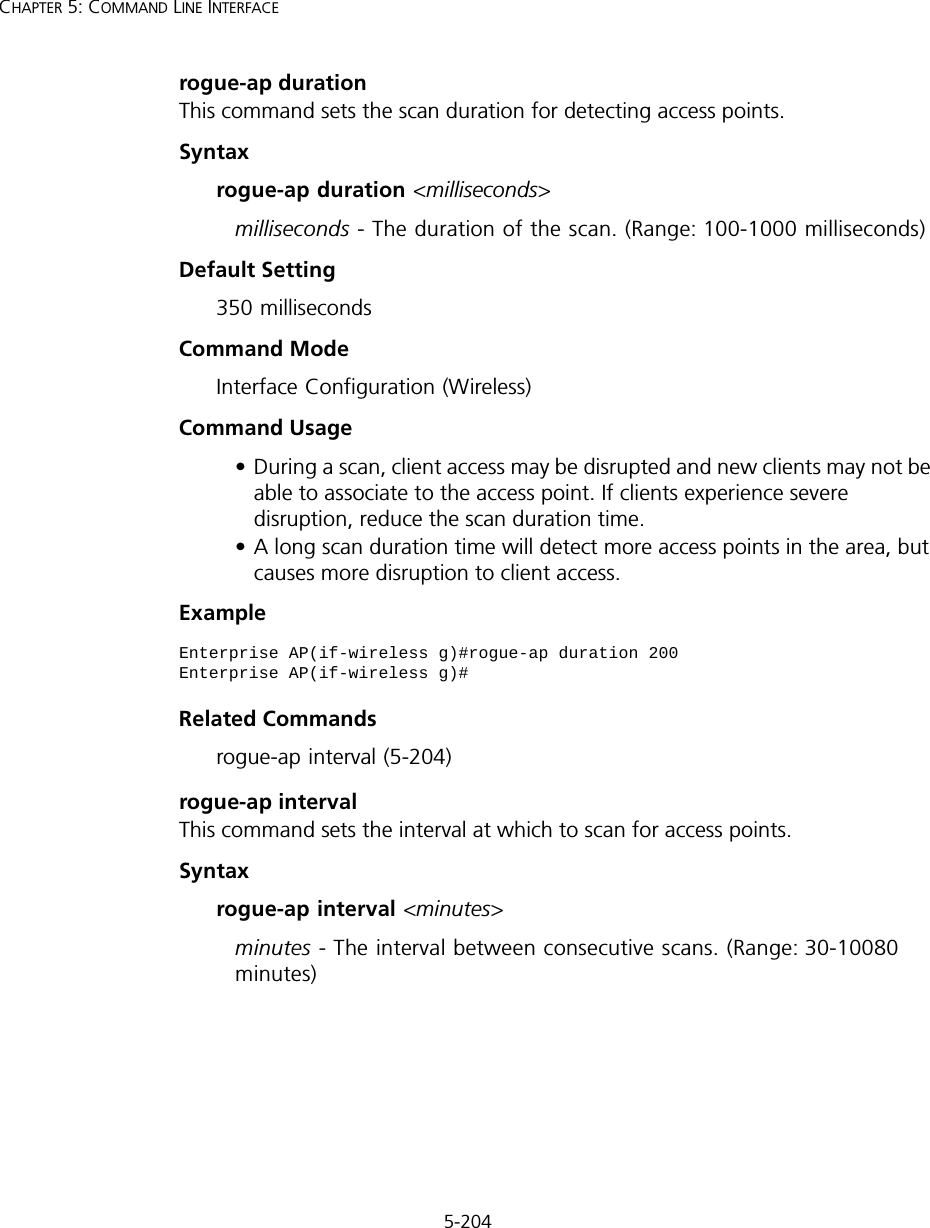
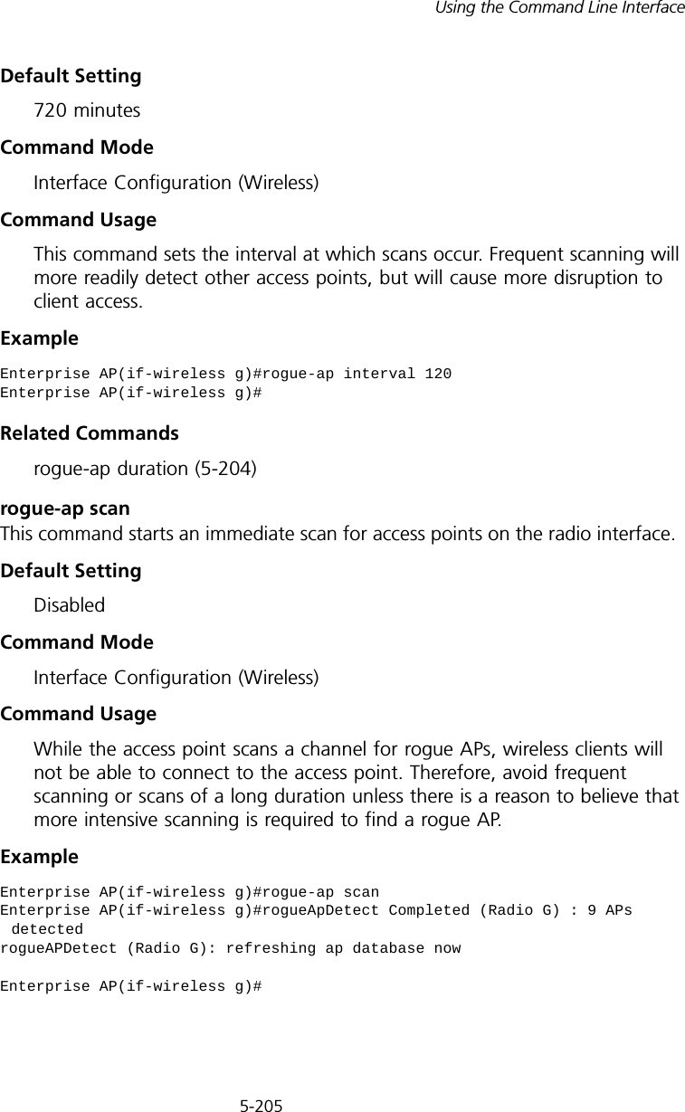
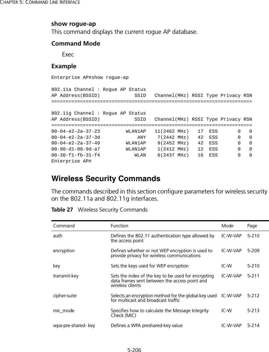
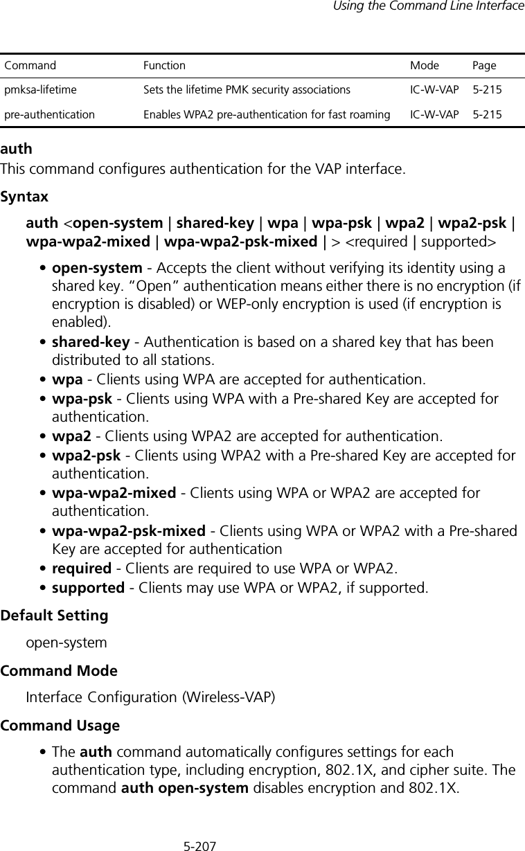
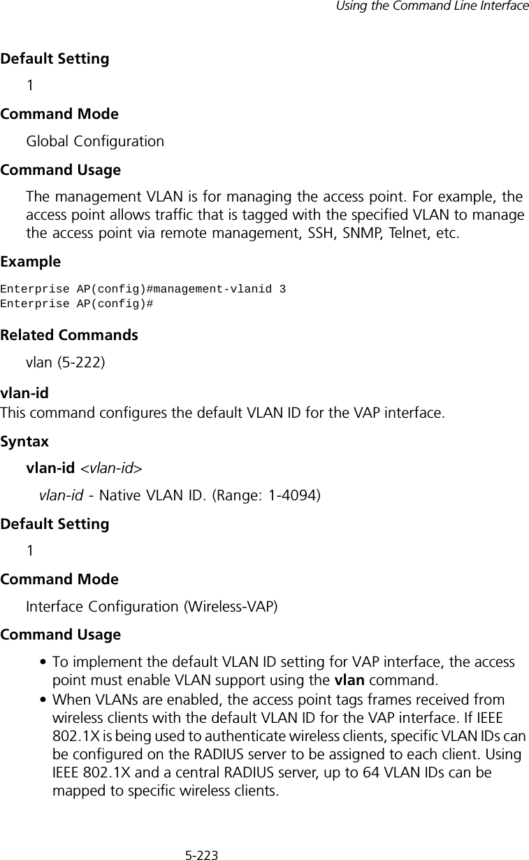
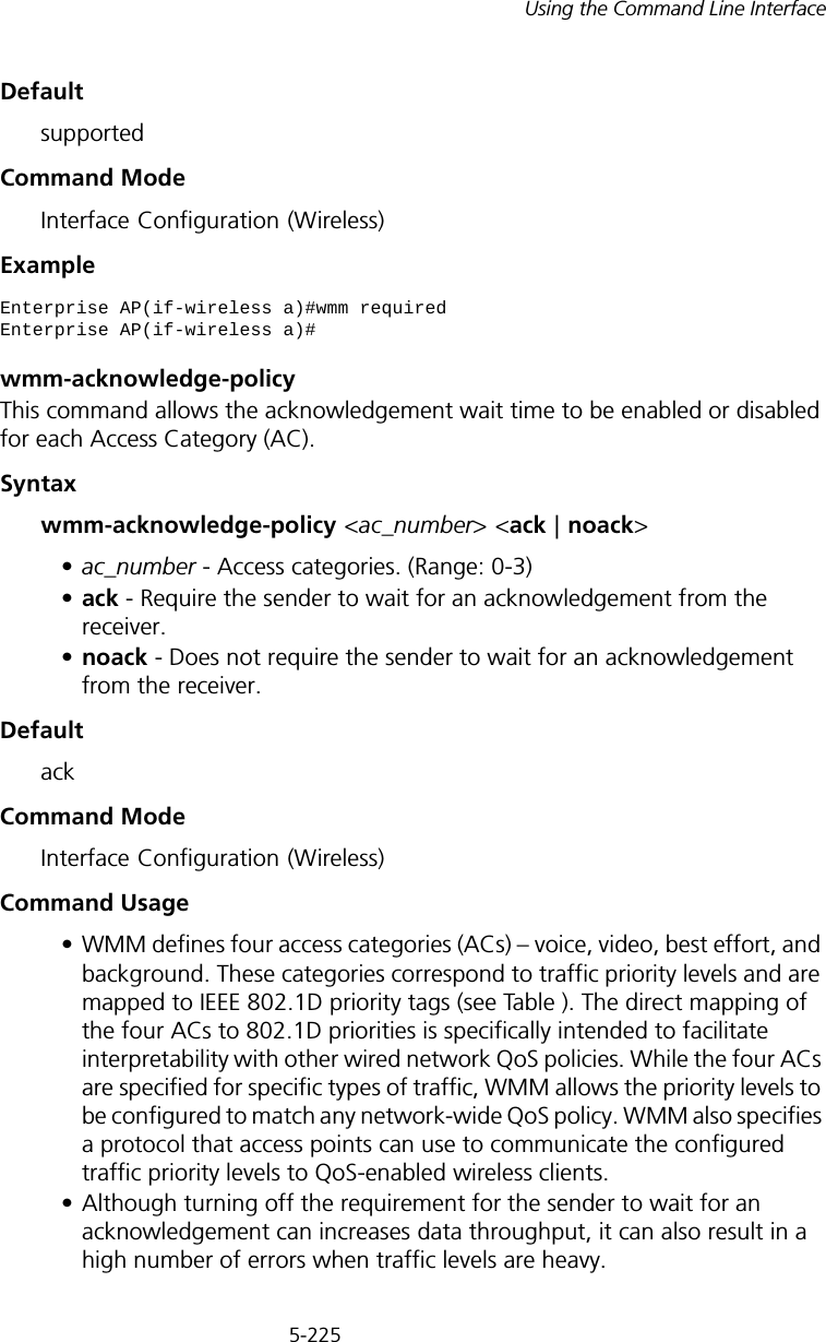
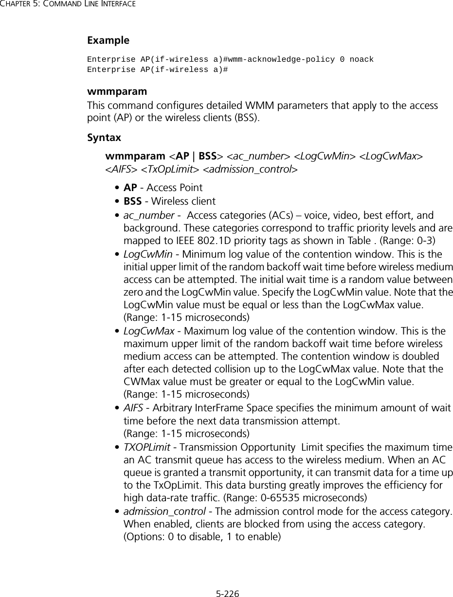
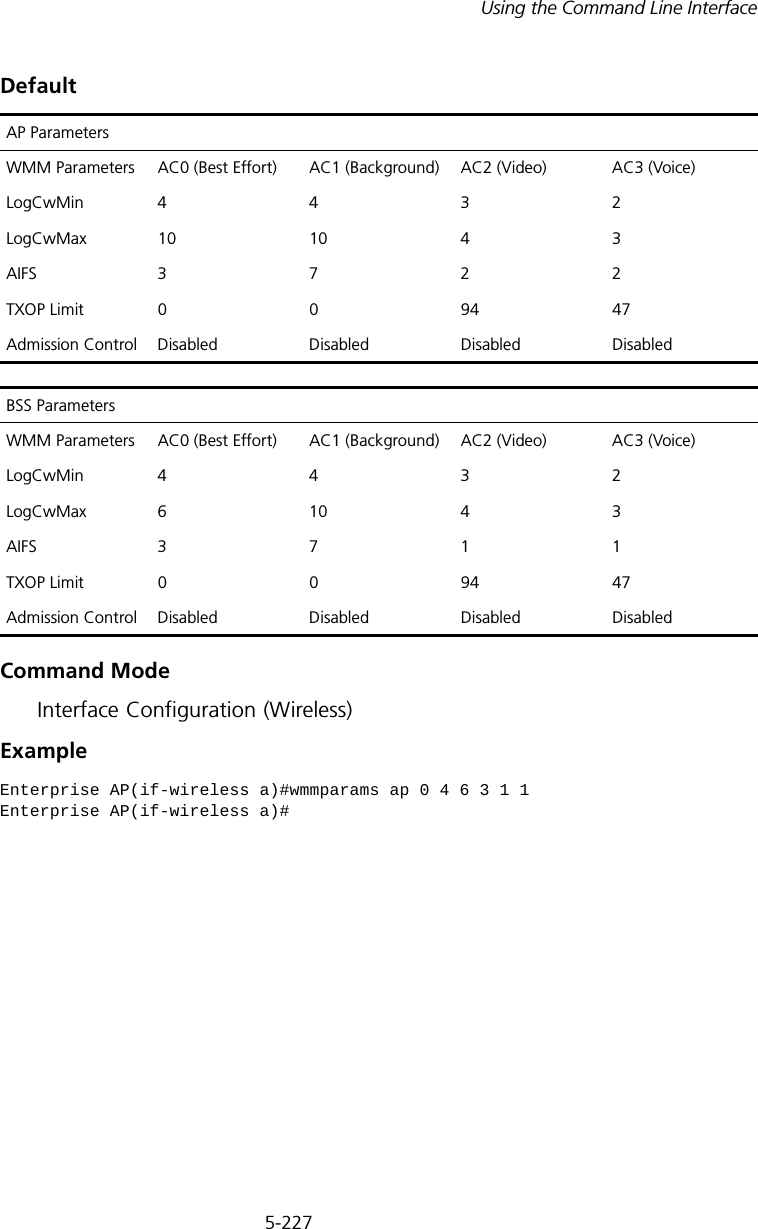
Hewlett Packard Enterprise WL546 Wireless 8760 Dual Radio 11a/b/g PoE Access Point User Manual WA6102X 2 32 UG booK

Hewlett-Packard Company Wireless 8760 Dual Radio 11a/b/g PoE Access Point WA6102X 2 32 UG booK

Contents

Users Manual2

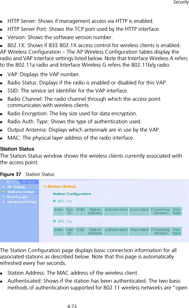
4-73SecurityHTTP Server: Shows if management access via HTTP is enabled.HTTP Server Port: Shows the TCP port used by the HTTP interface.Version: Shows the software version number.802.1X: Shows if IEEE 802.1X access control for wireless clients is enabled.AP Wireless Configuration – The AP Wireless Configuration tables display the radio and VAP interface settings listed below. Note that Interface Wireless A refers to the 802.11a radio and Interface Wireless G refers the 802.11b/g radio.VAP: Displays the VAP number.Radio Status: Displays if the radio is enabled or disabled for this VAP.SSID: The service set identifier for the VAP interface.Radio Channel: The radio channel through which the access point communicates with wireless clients.Radio Encryption: The key size used for data encryption.Radio Auth. Type: Shows the type of authentication used.Output Antenna: Displays which antenna/e are in use by the VAP.MAC: The physical layer address of the radio interface.Station StatusThe Station Status window shows the wireless clients currently associated with the access point.Figure 37   Station StatusThe Station Configuration page displays basic connection information for all associated stations as described below. Note that this page is automatically refreshed every five seconds. Station Address: The MAC address of the wireless client.Authenticated: Shows if the station has been authenticated. The two basic methods of authentication supported for 802.11 wireless networks are “open
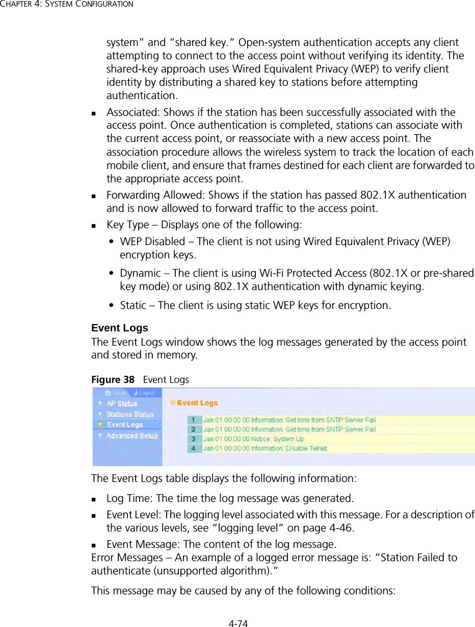
4-74CHAPTER 4: SYSTEM CONFIGURATIONsystem” and “shared key.” Open-system authentication accepts any client attempting to connect to the access point without verifying its identity. The shared-key approach uses Wired Equivalent Privacy (WEP) to verify client identity by distributing a shared key to stations before attempting authentication.Associated: Shows if the station has been successfully associated with the access point. Once authentication is completed, stations can associate with the current access point, or reassociate with a new access point. The association procedure allows the wireless system to track the location of each mobile client, and ensure that frames destined for each client are forwarded to the appropriate access point.Forwarding Allowed: Shows if the station has passed 802.1X authentication and is now allowed to forward traffic to the access point.Key Type – Displays one of the following:•  WEP Disabled – The client is not using Wired Equivalent Privacy (WEP) encryption keys.•  Dynamic – The client is using Wi-Fi Protected Access (802.1X or pre-shared key mode) or using 802.1X authentication with dynamic keying.•  Static – The client is using static WEP keys for encryption.Event LogsThe Event Logs window shows the log messages generated by the access point and stored in memory.Figure 38   Event LogsThe Event Logs table displays the following information:Log Time: The time the log message was generated.Event Level: The logging level associated with this message. For a description of the various levels, see “logging level” on page 4-46.Event Message: The content of the log message.Error Messages – An example of a logged error message is: “Station Failed to authenticate (unsupported algorithm).”This message may be caused by any of the following conditions:
4-75SecurityAccess point was set to “Open Authentication”, but a client sent an authentication request frame with a “Shared key.”Access point was set to “Shared Key Authentication,” but a client sent an authentication frame for “Open System.”WEP keys do not match: When the access point uses “Shared Key Authentication,” but the key used by client and access point are not the same, the frame will be decrypted incorrectly, using the wrong algorithm and sequence number.
4-76CHAPTER 4: SYSTEM CONFIGURATION
5-775COMMAND LINE INTERFACEUSING THE COMMAND LINE INTERFACEACCESSING THE CLIWhen accessing the management interface for the over a direct connection to the console port, or via a Telnet connection, the access point can be managed by entering command keywords and parameters at the prompt. Using the access point’s command-line interface (CLI) is very similar to entering commands on a UNIX system.CONSOLE CONNECTIONTo access the access point through the console port, perform these steps:1. At the console prompt, enter the user name and password. (The default user name is “admin” and the default password is “password”) When the user name is entered, the CLI displays the “Enterprise AP#” prompt. 2. Enter the necessary commands to complete your desired tasks. 3. When finished, exit the session with the “exit” command.After connecting to the system through the console port, the login screen displays:Username: adminPassword: Enterprise AP#NOTE: Command examples shown later in this chapter abbreviate the console prompt to “AP” for simplicity.
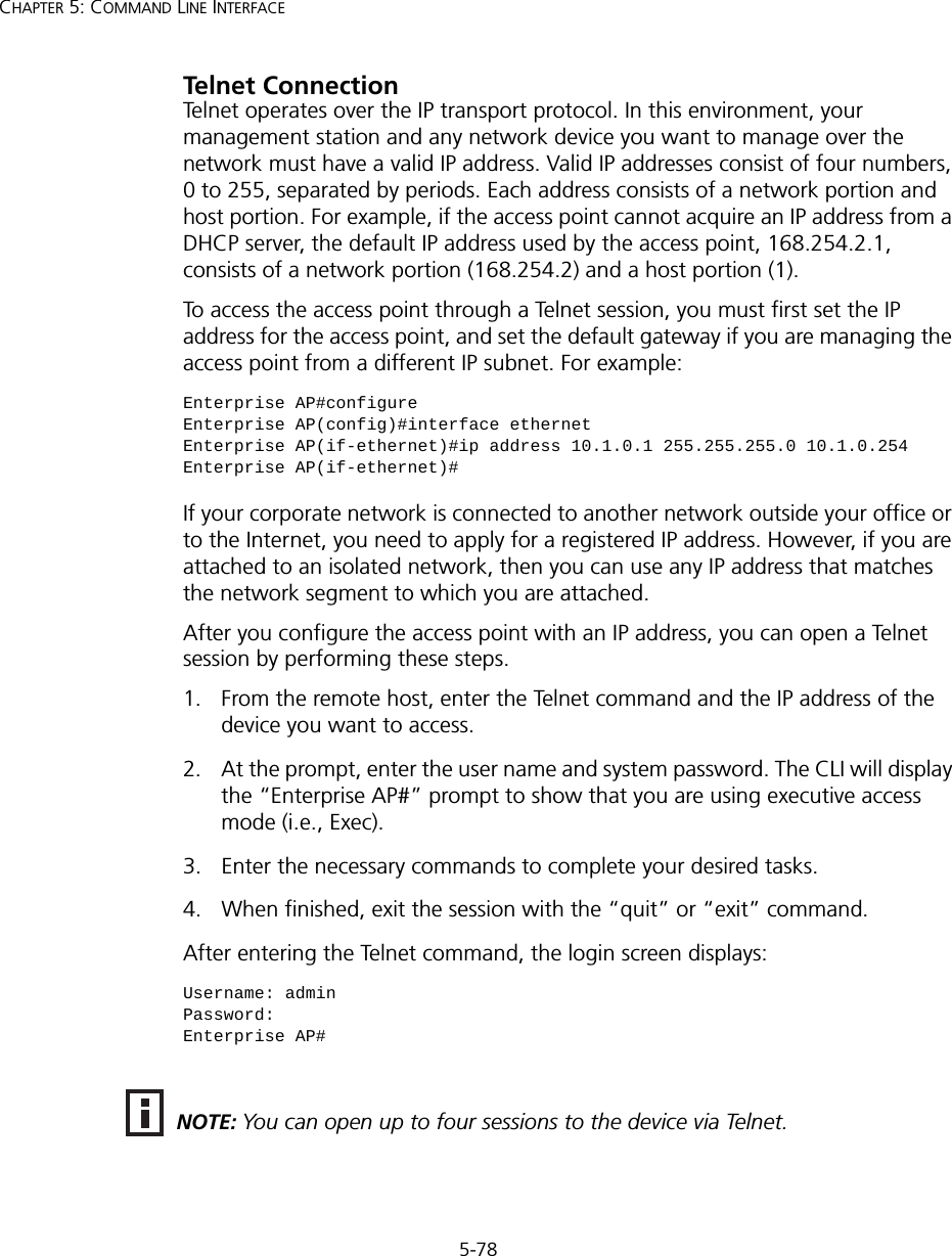
5-78CHAPTER 5: COMMAND LINE INTERFACETelnet ConnectionTelnet operates over the IP transport protocol. In this environment, your management station and any network device you want to manage over the network must have a valid IP address. Valid IP addresses consist of four numbers, 0 to 255, separated by periods. Each address consists of a network portion and host portion. For example, if the access point cannot acquire an IP address from a DHCP server, the default IP address used by the access point, 168.254.2.1, consists of a network portion (168.254.2) and a host portion (1).To access the access point through a Telnet session, you must first set the IP address for the access point, and set the default gateway if you are managing the access point from a different IP subnet. For example:If your corporate network is connected to another network outside your office or to the Internet, you need to apply for a registered IP address. However, if you are attached to an isolated network, then you can use any IP address that matches the network segment to which you are attached.After you configure the access point with an IP address, you can open a Telnet session by performing these steps.1. From the remote host, enter the Telnet command and the IP address of the device you want to access. 2. At the prompt, enter the user name and system password. The CLI will display the “Enterprise AP#” prompt to show that you are using executive access mode (i.e., Exec). 3. Enter the necessary commands to complete your desired tasks. 4. When finished, exit the session with the “quit” or “exit” command. After entering the Telnet command, the login screen displays:Enterprise AP#configureEnterprise AP(config)#interface ethernetEnterprise AP(if-ethernet)#ip address 10.1.0.1 255.255.255.0 10.1.0.254Enterprise AP(if-ethernet)#Username: adminPassword: Enterprise AP#NOTE: You can open up to four sessions to the device via Telnet.
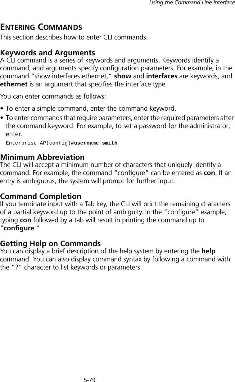
5-79Using the Command Line InterfaceENTERING COMMANDSThis section describes how to enter CLI commands.Keywords and ArgumentsA CLI command is a series of keywords and arguments. Keywords identify a command, and arguments specify configuration parameters. For example, in the command “show interfaces ethernet,” show and interfaces are keywords, and ethernet is an argument that specifies the interface type.You can enter commands as follows:• To enter a simple command, enter the command keyword. • To enter commands that require parameters, enter the required parameters after the command keyword. For example, to set a password for the administrator, enter:Enterprise AP(config)#username smithMinimum AbbreviationThe CLI will accept a minimum number of characters that uniquely identify a command. For example, the command “configure” can be entered as con. If an entry is ambiguous, the system will prompt for further input.Command CompletionIf you terminate input with a Tab key, the CLI will print the remaining characters of a partial keyword up to the point of ambiguity. In the “configure” example, typing con followed by a tab will result in printing the command up to “configure.”Getting Help on CommandsYou can display a brief description of the help system by entering the help command. You can also display command syntax by following a command with the “?” character to list keywords or parameters.
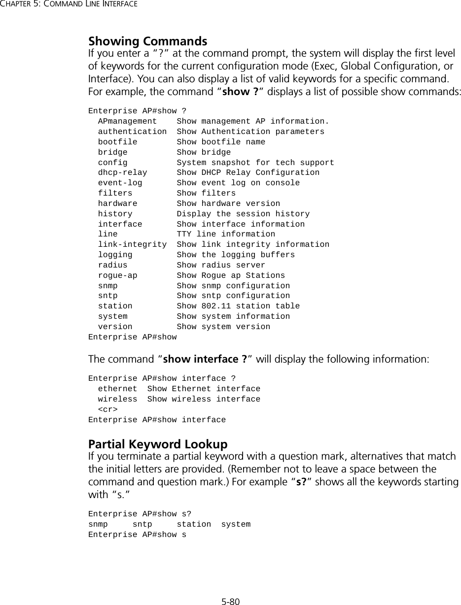
5-80CHAPTER 5: COMMAND LINE INTERFACEShowing CommandsIf you enter a “?” at the command prompt, the system will display the first level of keywords for the current configuration mode (Exec, Global Configuration, or Interface). You can also display a list of valid keywords for a specific command. For example, the command “show ?” displays a list of possible show commands:The command “show interface ?” will display the following information:Partial Keyword LookupIf you terminate a partial keyword with a question mark, alternatives that match the initial letters are provided. (Remember not to leave a space between the command and question mark.) For example “s?” shows all the keywords starting with “s.”Enterprise AP#show ?  APmanagement    Show management AP information.  authentication  Show Authentication parameters  bootfile        Show bootfile name  bridge          Show bridge  config          System snapshot for tech support  dhcp-relay      Show DHCP Relay Configuration  event-log       Show event log on console  filters         Show filters  hardware        Show hardware version  history         Display the session history  interface       Show interface information  line            TTY line information  link-integrity  Show link integrity information  logging         Show the logging buffers  radius          Show radius server  rogue-ap        Show Rogue ap Stations  snmp            Show snmp configuration  sntp            Show sntp configuration  station         Show 802.11 station table  system          Show system information  version         Show system versionEnterprise AP#showEnterprise AP#show interface ?  ethernet  Show Ethernet interface  wireless  Show wireless interface  <cr>Enterprise AP#show interfaceEnterprise AP#show s?snmp     sntp     station  systemEnterprise AP#show s
5-81Using the Command Line InterfaceNegating the Effect of CommandsFor many configuration commands you can enter the prefix keyword “no” to cancel the effect of a command or reset the configuration to the default value. For example, the logging command will log system messages to a host server. To disable logging, specify the no logging command. This guide describes the negation effect for all applicable commands.Using Command HistoryThe CLI maintains a history of commands that have been entered. You can scroll back through the history of commands by pressing the up arrow key. Any command displayed in the history list can be executed again, or first modified and then executed. Using the show history command displays a longer list of recently executed commands. Understanding Command ModesThe command set is divided into Exec and Configuration classes. Exec commands generally display information on system status or clear statistical counters. Configuration commands, on the other hand, modify interface parameters or enable certain functions. These classes are further divided into different modes. Available commands depend on the selected mode. You can always enter a question mark “?” at the prompt to display a list of the commands available for the current mode. The command classes and associated modes are displayed in the following table:Table 7   Command ModesExec CommandsWhen you open a new console session on an access point, the system enters Exec command mode. Only a limited number of the commands are available in this mode. You can access all other commands only from the configuration mode. To access Exec mode, open a new console session with the user name “admin.” The command prompt displays as “Enterprise AP#” for Exec mode. Class ModeExec PrivilegedConfiguration GlobalInterface-ethernetInterface-wirelessInterface-wireless-vapUsername: adminPassword: [system login password]Enterprise AP#
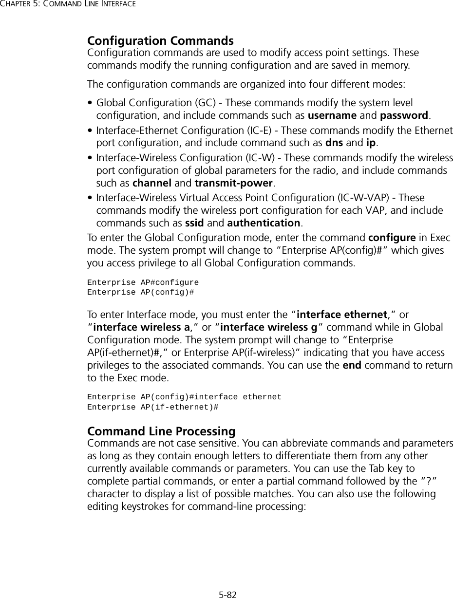
5-82CHAPTER 5: COMMAND LINE INTERFACEConfiguration CommandsConfiguration commands are used to modify access point settings. These commands modify the running configuration and are saved in memory. The configuration commands are organized into four different modes:• Global Configuration (GC) - These commands modify the system level configuration, and include commands such as username and password. • Interface-Ethernet Configuration (IC-E) - These commands modify the Ethernet port configuration, and include command such as dns and ip.• Interface-Wireless Configuration (IC-W) - These commands modify the wireless port configuration of global parameters for the radio, and include commands such as channel and transmit-power.• Interface-Wireless Virtual Access Point Configuration (IC-W-VAP) - These commands modify the wireless port configuration for each VAP, and include commands such as ssid and authentication.To enter the Global Configuration mode, enter the command configure in Exec mode. The system prompt will change to “Enterprise AP(config)#” which gives you access privilege to all Global Configuration commands.To enter Interface mode, you must enter the “interface ethernet,” or “interface wireless a,” or “interface wireless g” command while in Global Configuration mode. The system prompt will change to “Enterprise AP(if-ethernet)#,” or Enterprise AP(if-wireless)” indicating that you have access privileges to the associated commands. You can use the end command to return to the Exec mode.Command Line ProcessingCommands are not case sensitive. You can abbreviate commands and parameters as long as they contain enough letters to differentiate them from any other currently available commands or parameters. You can use the Tab key to complete partial commands, or enter a partial command followed by the “?” character to display a list of possible matches. You can also use the following editing keystrokes for command-line processing:Enterprise AP#configureEnterprise AP(config)#Enterprise AP(config)#interface ethernetEnterprise AP(if-ethernet)#
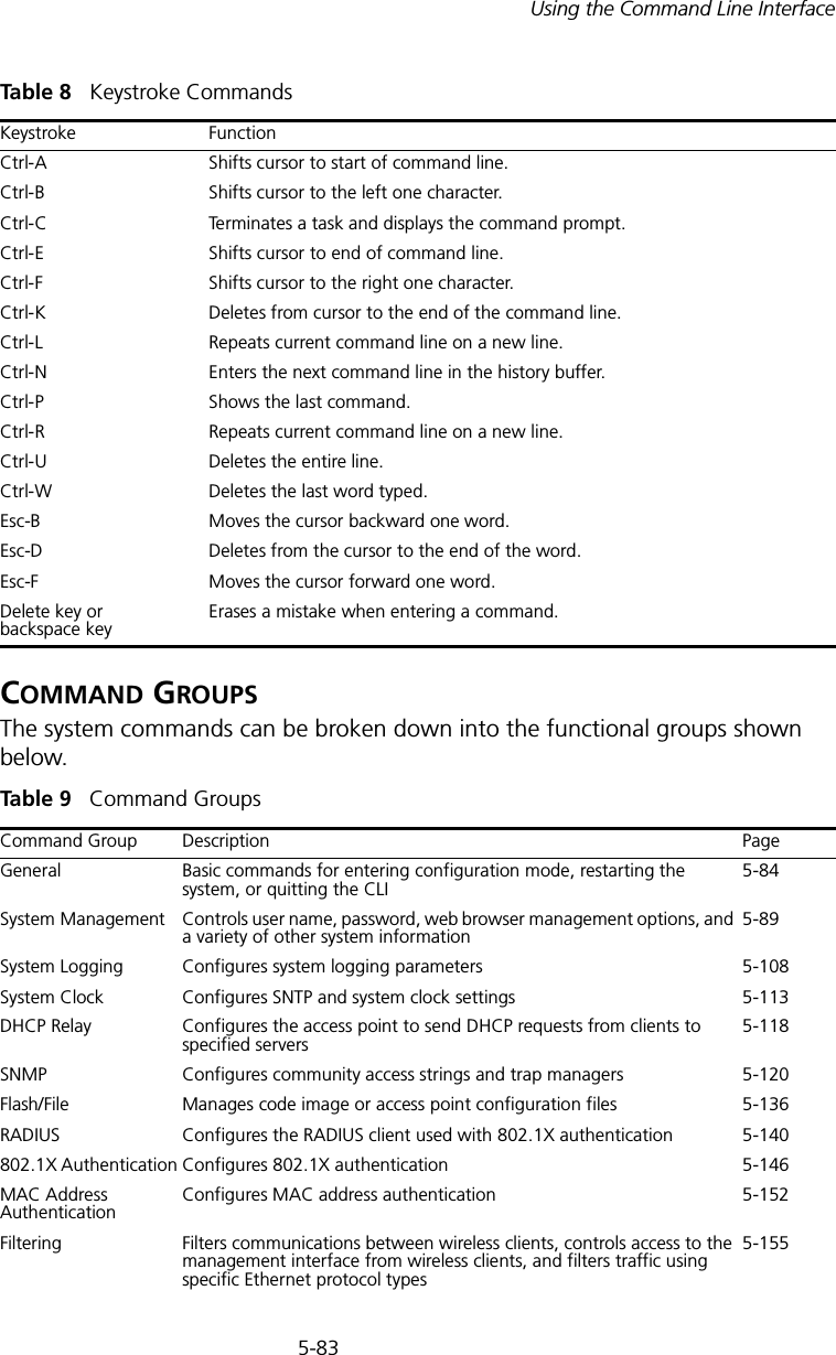
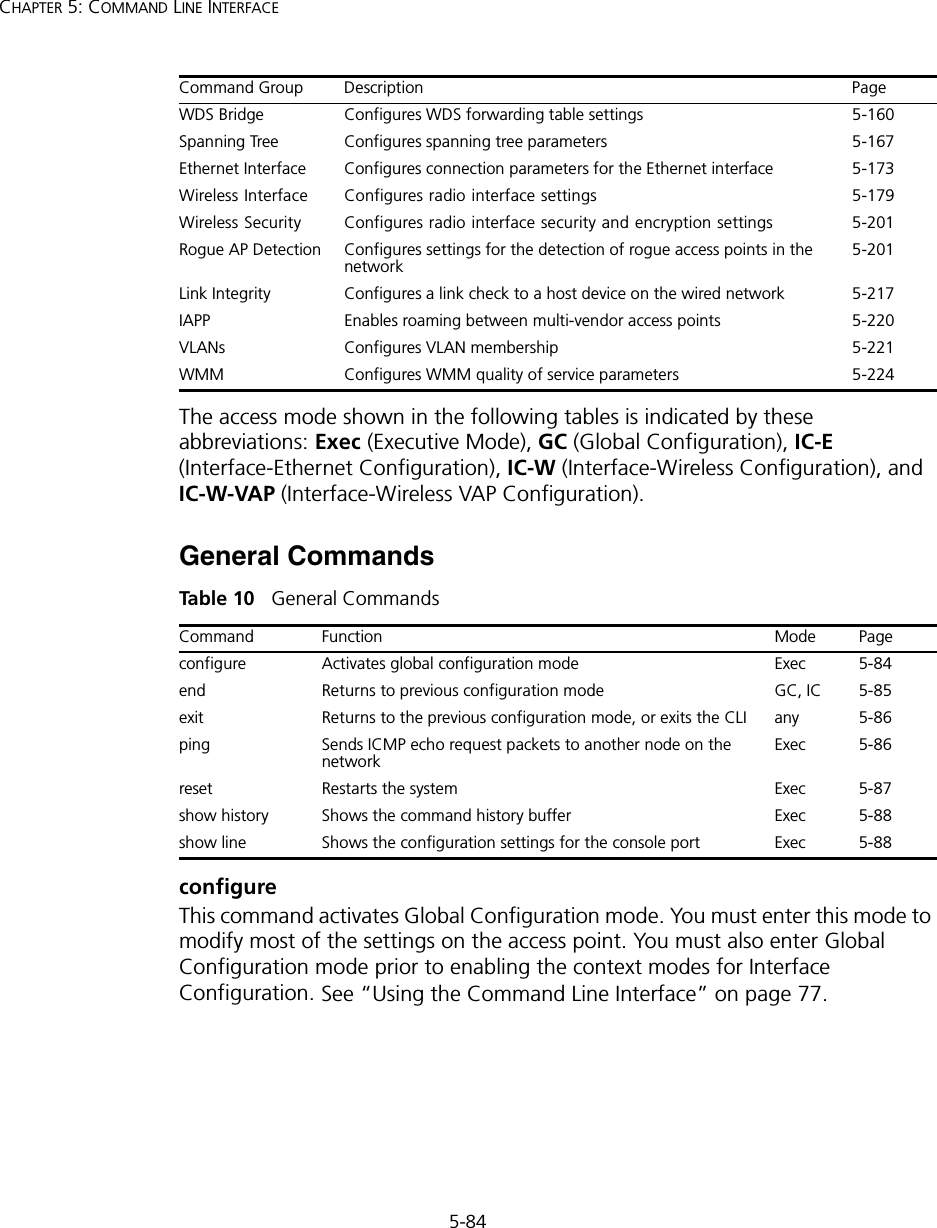
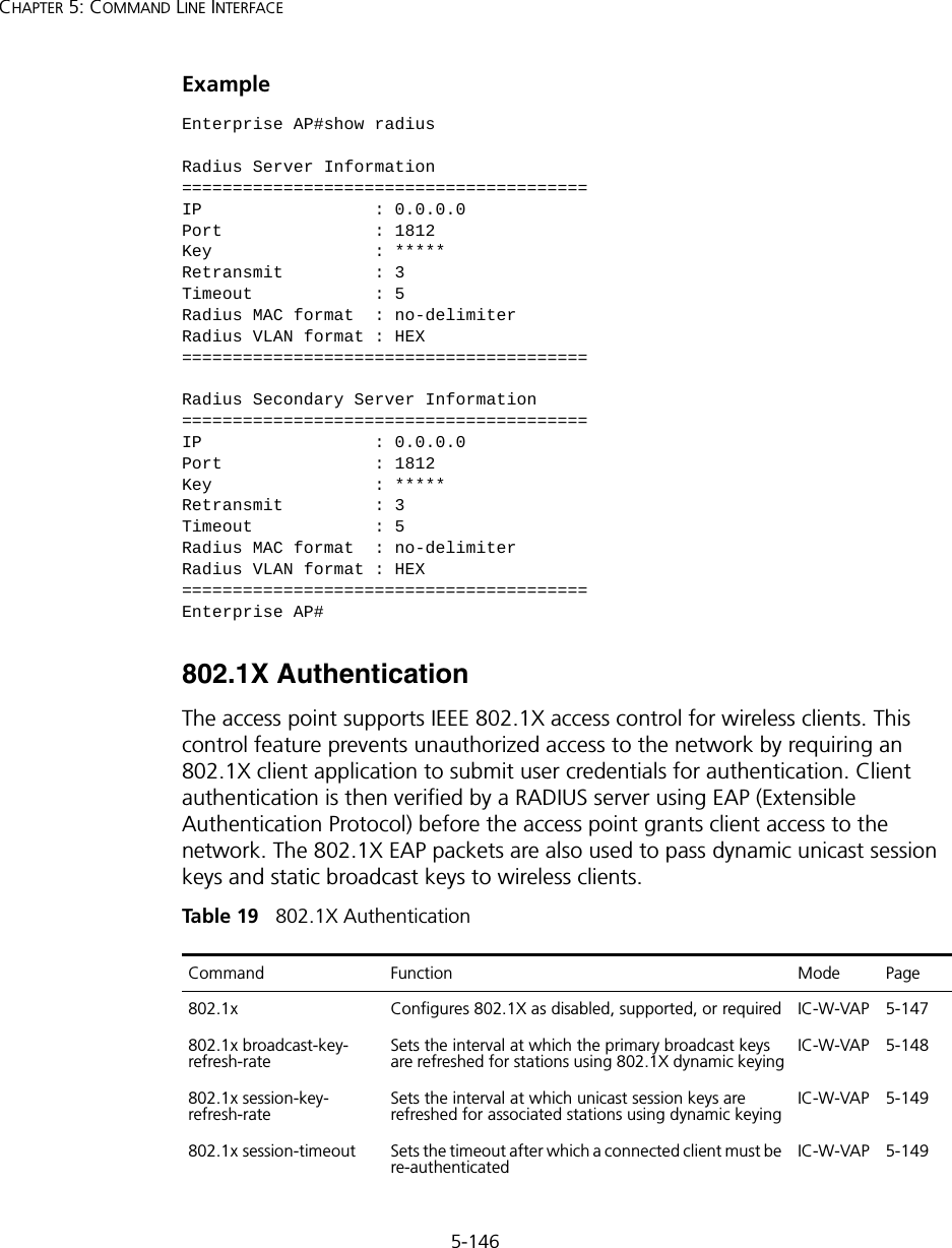
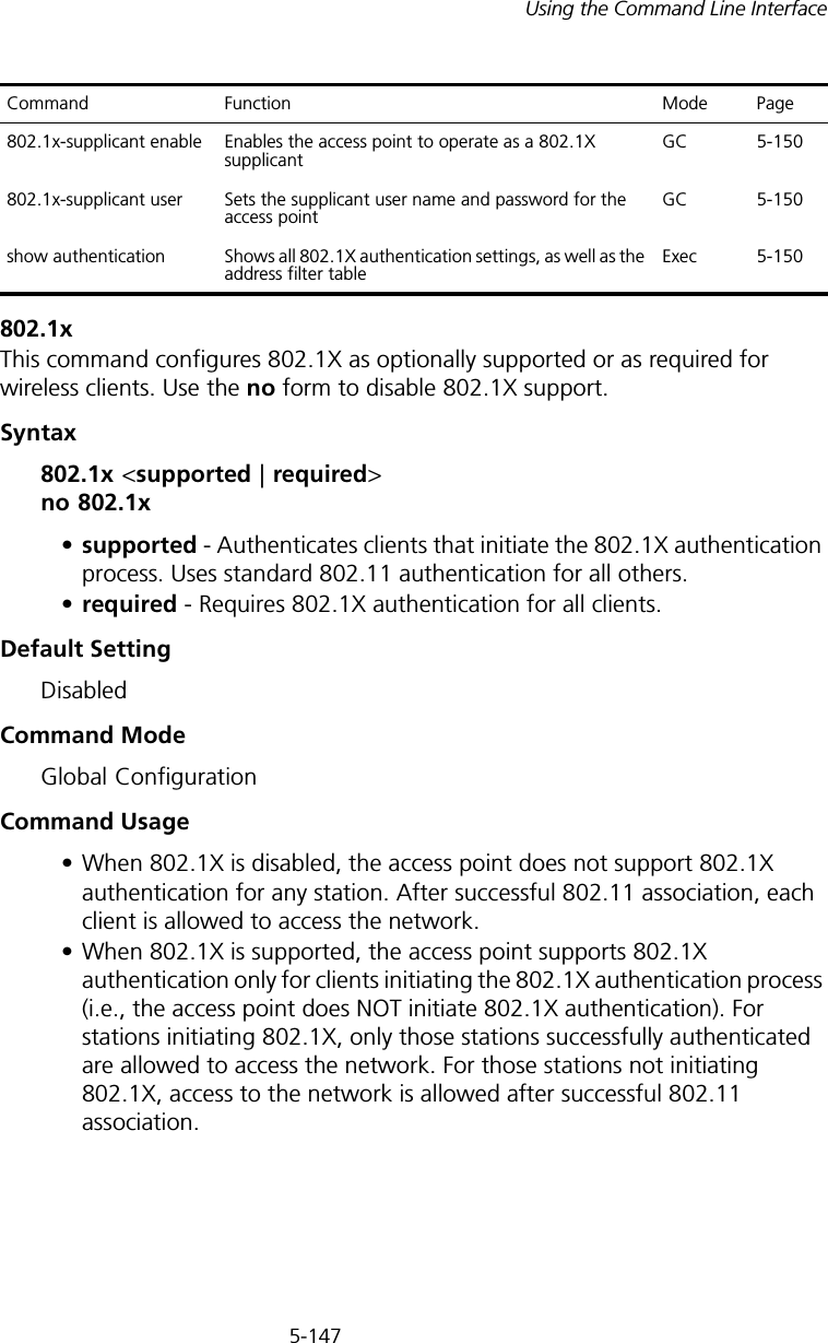
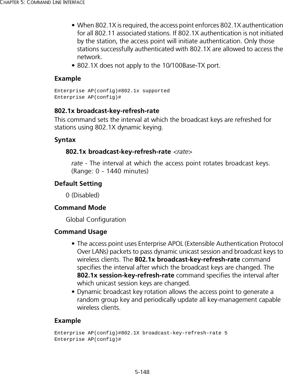
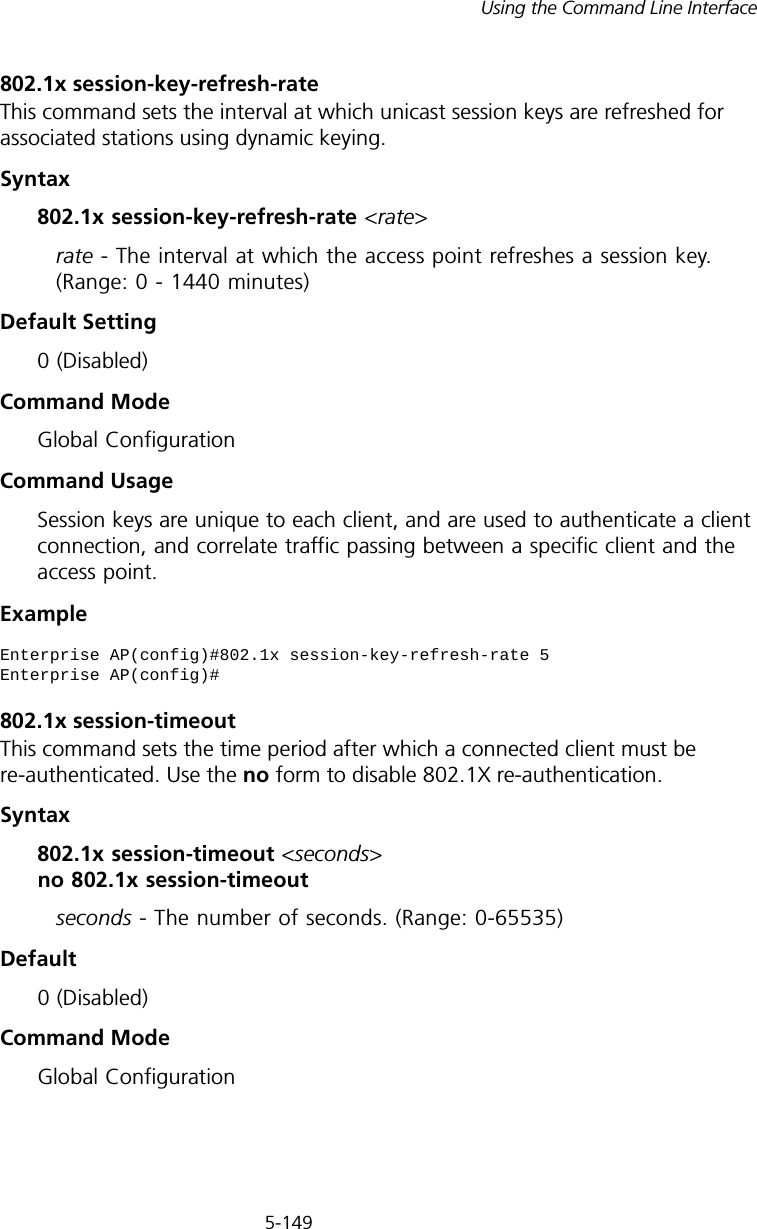
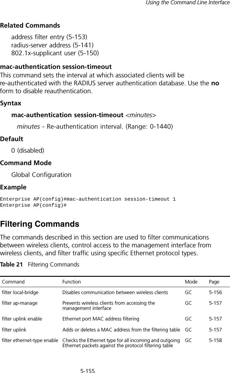
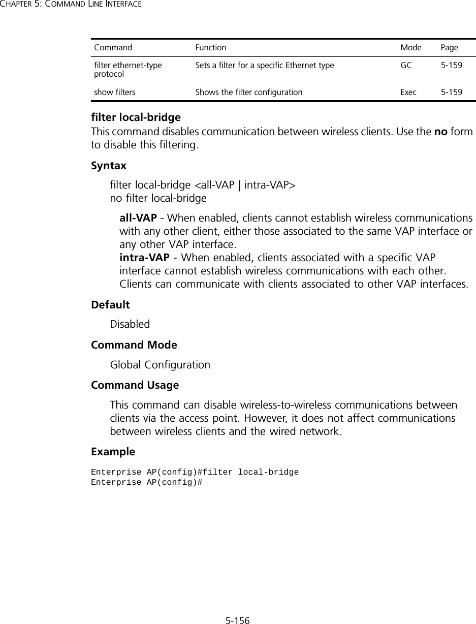
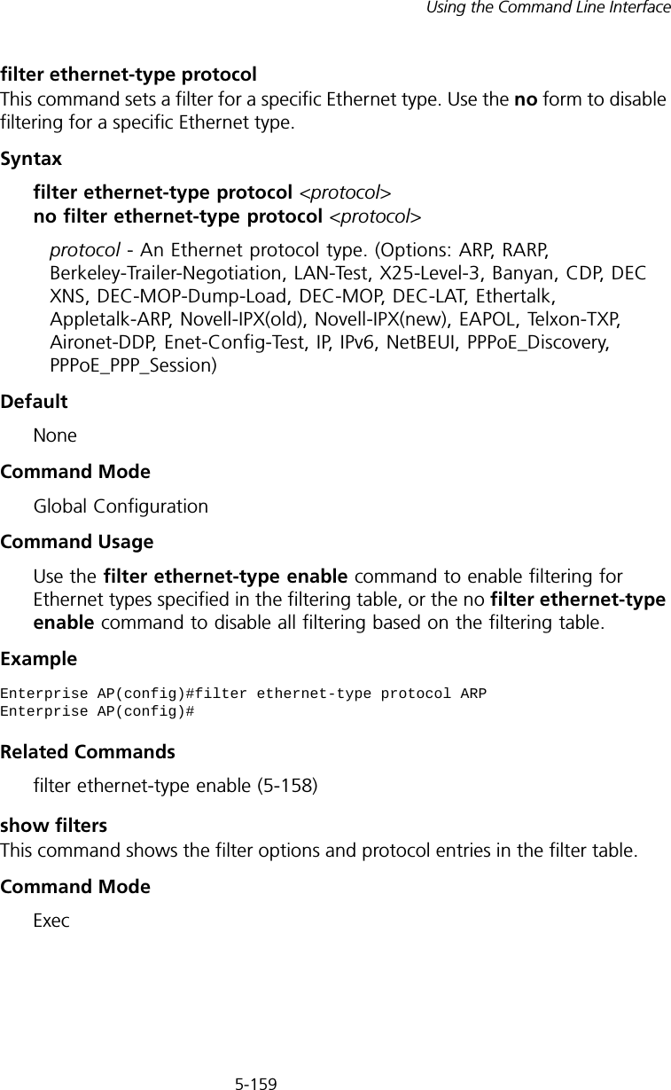
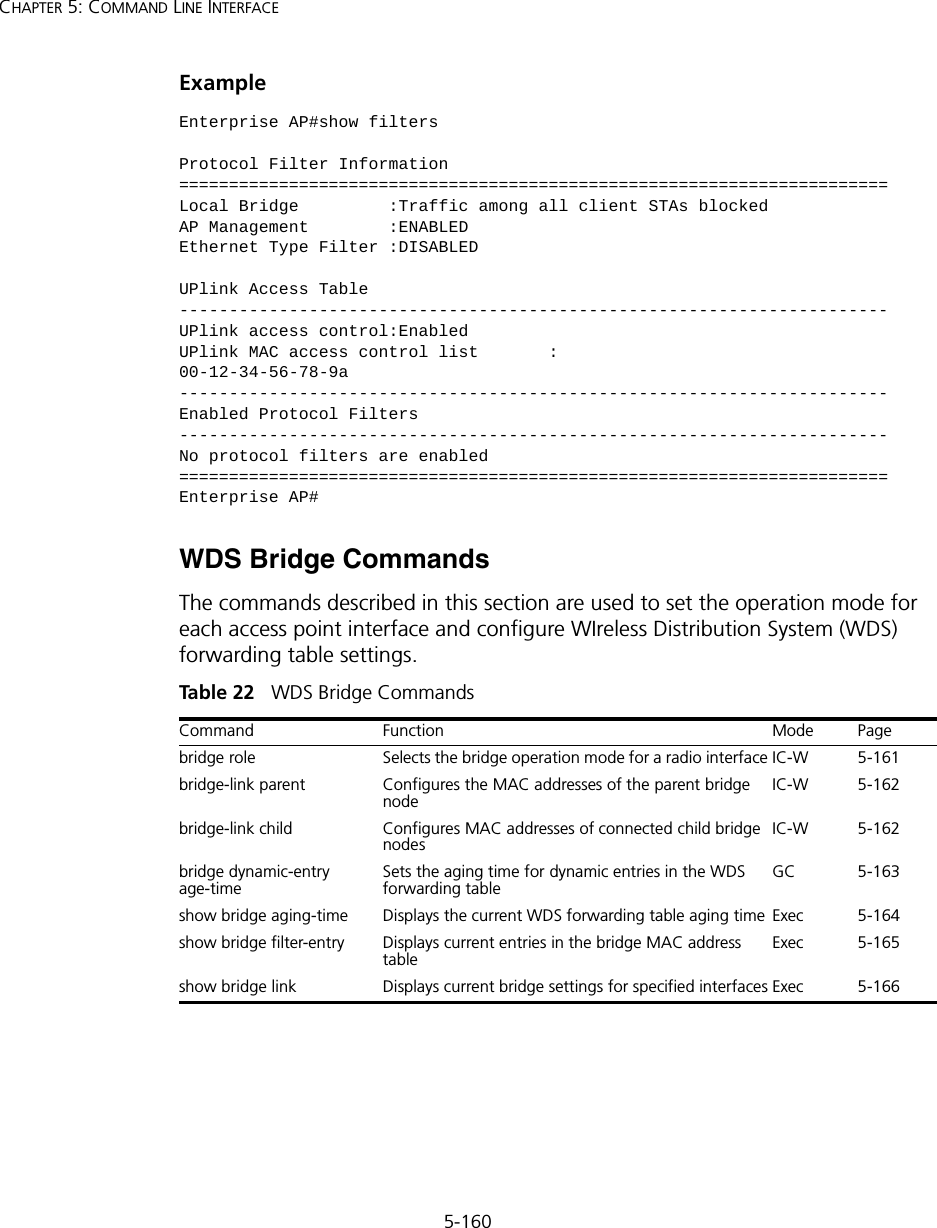
5-83Using the Command Line InterfaceTable 8   Keystroke CommandsCOMMAND GROUPSThe system commands can be broken down into the functional groups shown below.Table 9   Command GroupsKeystroke FunctionCtrl-A Shifts cursor to start of command line. Ctrl-B Shifts cursor to the left one character.Ctrl-C Terminates a task and displays the command prompt.Ctrl-E Shifts cursor to end of command line.Ctrl-F Shifts cursor to the right one character.Ctrl-K Deletes from cursor to the end of the command line.Ctrl-L Repeats current command line on a new line.Ctrl-N Enters the next command line in the history buffer.Ctrl-P Shows the last command.Ctrl-R Repeats current command line on a new line.Ctrl-U  Deletes the entire line.Ctrl-W  Deletes the last word typed.Esc-B Moves the cursor backward one word.Esc-D Deletes from the cursor to the end of the word.Esc-F Moves the cursor forward one word.Delete key or backspace key Erases a mistake when entering a command.Command Group Description PageGeneral Basic commands for entering configuration mode, restarting the system, or quitting the CLI  5-84System Management Controls user name, password, web browser management options, and a variety of other system information 5-89System Logging Configures system logging parameters 5-108System Clock Configures SNTP and system clock settings 5-113DHCP Relay Configures the access point to send DHCP requests from clients to specified servers5-118SNMP Configures community access strings and trap managers 5-120Flash/File Manages code image or access point configuration files  5-136RADIUS Configures the RADIUS client used with 802.1X authentication 5-140802.1X Authentication Configures 802.1X authentication 5-146MAC Address Authentication Configures MAC address authentication 5-152Filtering Filters communications between wireless clients, controls access to the management interface from wireless clients, and filters traffic using specific Ethernet protocol types5-155
5-84CHAPTER 5: COMMAND LINE INTERFACEThe access mode shown in the following tables is indicated by these abbreviations: Exec (Executive Mode), GC (Global Configuration), IC-E (Interface-Ethernet Configuration), IC-W (Interface-Wireless Configuration), and IC-W-VAP (Interface-Wireless VAP Configuration).General CommandsTable 10   General CommandsconfigureThis command activates Global Configuration mode. You must enter this mode to modify most of the settings on the access point. You must also enter Global Configuration mode prior to enabling the context modes for Interface Configuration. See “Using the Command Line Interface” on page 77.WDS Bridge Configures WDS forwarding table settings 5-160Spanning Tree Configures spanning tree parameters 5-167Ethernet Interface Configures connection parameters for the Ethernet interface 5-173Wireless Interface Configures radio interface settings 5-179Wireless Security Configures radio interface security and encryption settings 5-201Rogue AP Detection Configures settings for the detection of rogue access points in the network5-201Link Integrity Configures a link check to a host device on the wired network 5-217IAPP Enables roaming between multi-vendor access points 5-220VLANs Configures VLAN membership  5-221WMM Configures WMM quality of service parameters 5-224Command Function Mode Pageconfigure  Activates global configuration mode  Exec 5-84end  Returns to previous configuration mode  GC, IC 5-85exit  Returns to the previous configuration mode, or exits the CLI  any 5-86ping  Sends ICMP echo request packets to another node on the network  Exec  5-86reset  Restarts the system  Exec 5-87show history  Shows the command history buffer  Exec  5-88show line Shows the configuration settings for the console port Exec 5-88Command Group Description Page
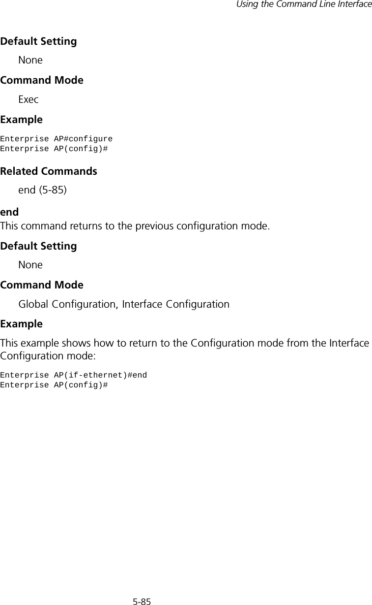
5-85Using the Command Line InterfaceDefault Setting NoneCommand Mode ExecExample Related Commands end (5-85)endThis command returns to the previous configuration mode.Default Setting NoneCommand Mode Global Configuration, Interface ConfigurationExample This example shows how to return to the Configuration mode from the Interface Configuration mode:Enterprise AP#configureEnterprise AP(config)#Enterprise AP(if-ethernet)#endEnterprise AP(config)#
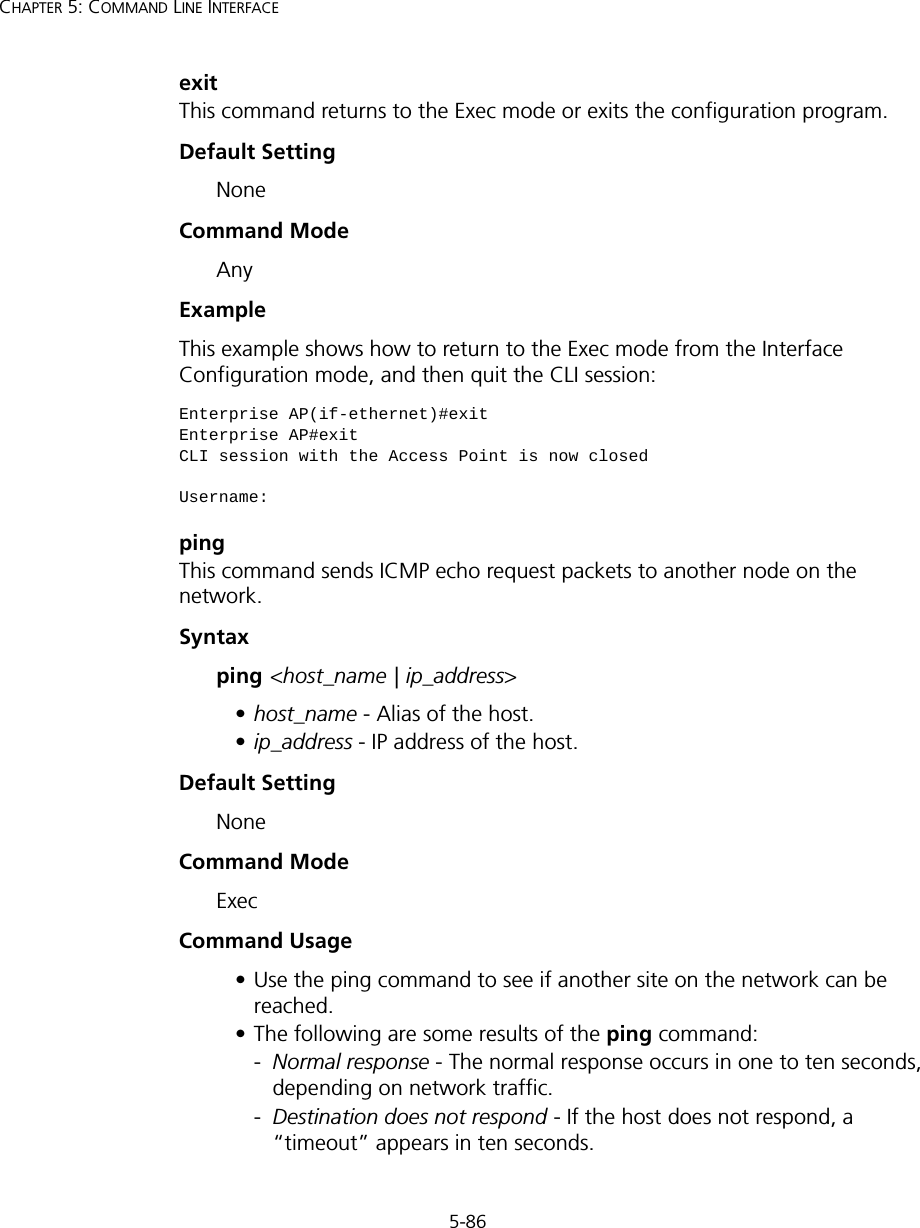
5-86CHAPTER 5: COMMAND LINE INTERFACEexitThis command returns to the Exec mode or exits the configuration program.Default Setting NoneCommand Mode AnyExample This example shows how to return to the Exec mode from the Interface Configuration mode, and then quit the CLI session:pingThis command sends ICMP echo request packets to another node on the network.Syntax ping <host_name | ip_address> •host_name - Alias of the host. •ip_address - IP address of the host.Default Setting NoneCommand Mode ExecCommand Usage • Use the ping command to see if another site on the network can be reached. • The following are some results of the ping command: -Normal response - The normal response occurs in one to ten seconds, depending on network traffic. -Destination does not respond - If the host does not respond, a “timeout” appears in ten seconds. Enterprise AP(if-ethernet)#exitEnterprise AP#exitCLI session with the Access Point is now closedUsername:
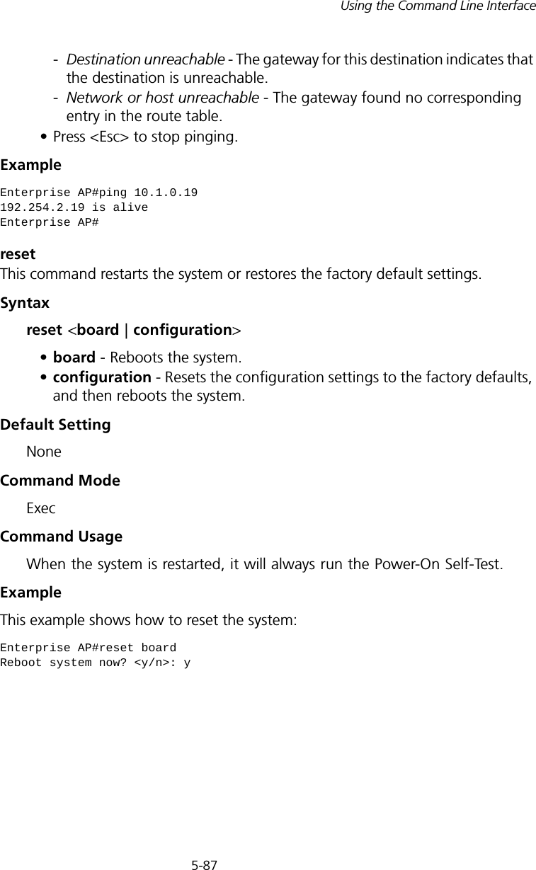
5-87Using the Command Line Interface-Destination unreachable - The gateway for this destination indicates that the destination is unreachable. -Network or host unreachable - The gateway found no corresponding entry in the route table. • Press <Esc> to stop pinging.Example resetThis command restarts the system or restores the factory default settings.Syntax reset <board | configuration> •board - Reboots the system. •configuration - Resets the configuration settings to the factory defaults, and then reboots the system.Default Setting NoneCommand Mode ExecCommand Usage When the system is restarted, it will always run the Power-On Self-Test. Example This example shows how to reset the system:Enterprise AP#ping 10.1.0.19192.254.2.19 is aliveEnterprise AP#Enterprise AP#reset boardReboot system now? <y/n>: y
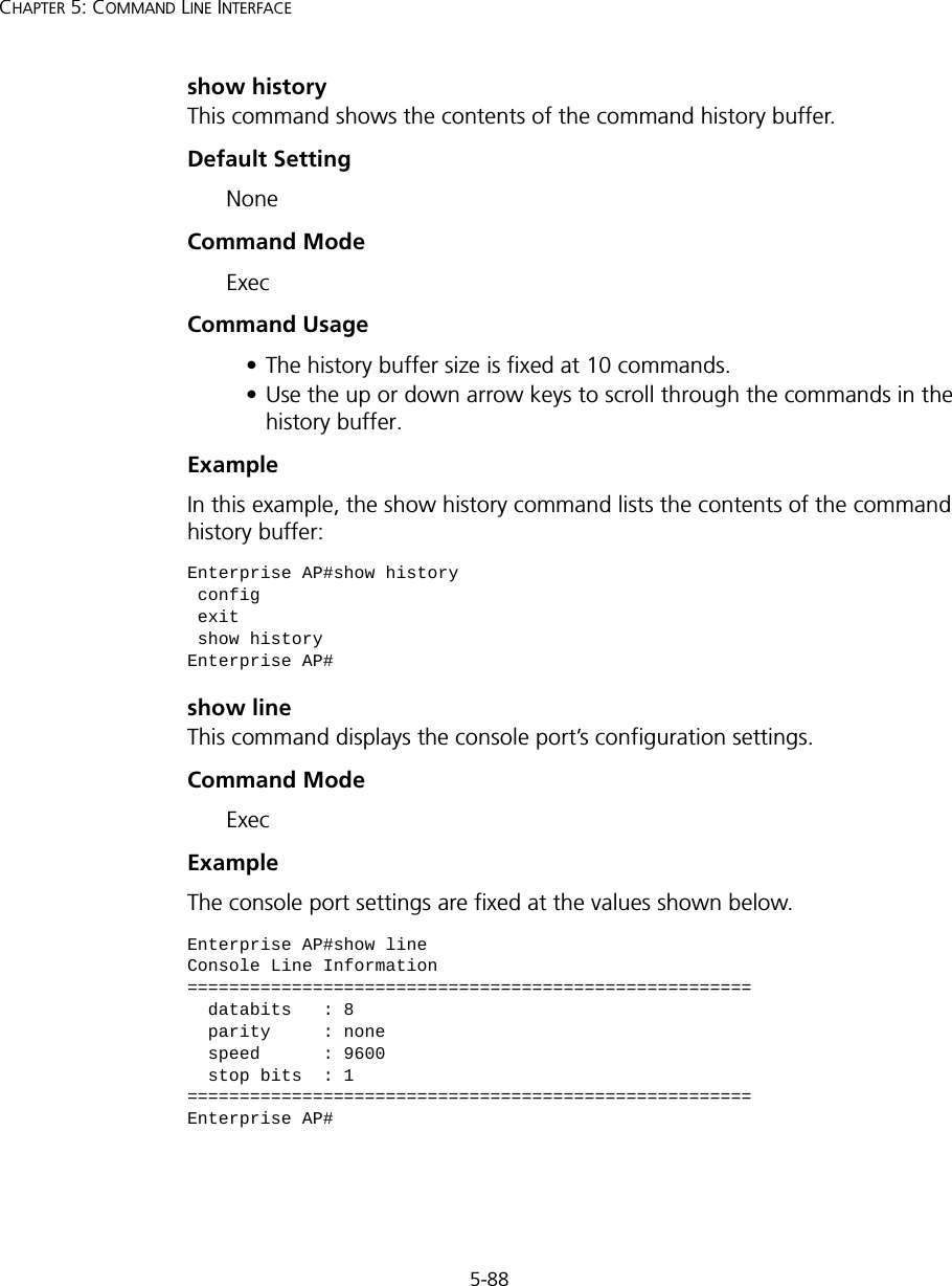
5-88CHAPTER 5: COMMAND LINE INTERFACEshow historyThis command shows the contents of the command history buffer.Default Setting NoneCommand Mode ExecCommand Usage • The history buffer size is fixed at 10 commands.• Use the up or down arrow keys to scroll through the commands in the history buffer.Example In this example, the show history command lists the contents of the command history buffer:show lineThis command displays the console port’s configuration settings.Command Mode ExecExampleThe console port settings are fixed at the values shown below.Enterprise AP#show history config exit show historyEnterprise AP#Enterprise AP#show lineConsole Line Information======================================================  databits   : 8  parity     : none  speed      : 9600  stop bits  : 1======================================================Enterprise AP#
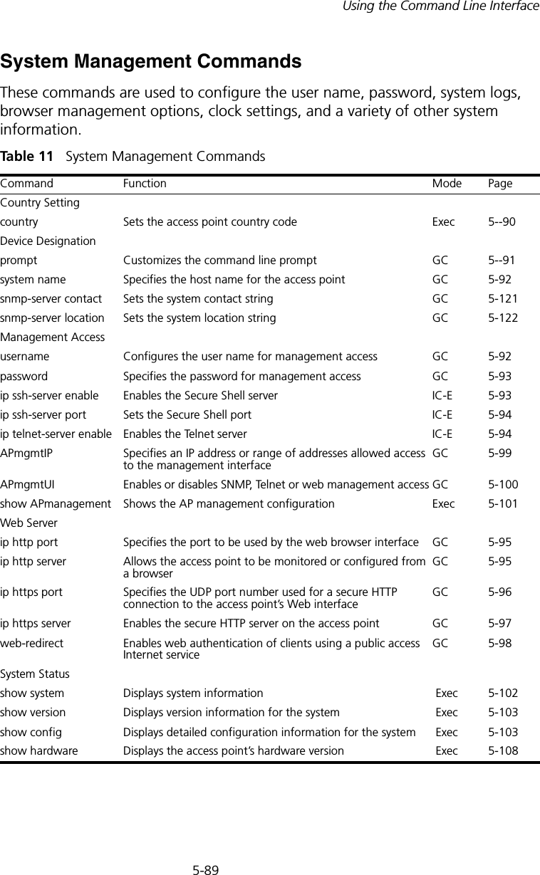
5-89Using the Command Line InterfaceSystem Management CommandsThese commands are used to configure the user name, password, system logs, browser management options, clock settings, and a variety of other system information.Table 11   System Management CommandsCommand Function Mode PageCountry Settingcountry Sets the access point country code Exec 5--90Device Designationprompt Customizes the command line prompt  GC 5--91system name Specifies the host name for the access point GC 5-92snmp-server contact  Sets the system contact string GC 5-121snmp-server location  Sets the system location string  GC 5-122Management Access username Configures the user name for management access GC 5-92password  Specifies the password for management access GC 5-93ip ssh-server enable Enables the Secure Shell server IC-E 5-93ip ssh-server port Sets the Secure Shell port IC-E 5-94ip telnet-server enable Enables the Telnet server IC-E 5-94APmgmtIP Specifies an IP address or range of addresses allowed access to the management interfaceGC 5-99APmgmtUI Enables or disables SNMP, Telnet or web management access GC 5-100show APmanagement Shows the AP management configuration Exec 5-101Web Serverip http port  Specifies the port to be used by the web browser interface  GC 5-95ip http server  Allows the access point to be monitored or configured from a browser GC 5-95ip https port Specifies the UDP port number used for a secure HTTP connection to the access point’s Web interfaceGC 5-96ip https server Enables the secure HTTP server on the access point  GC 5-97web-redirect Enables web authentication of clients using a public access Internet service GC 5-98System Statusshow system  Displays system information  Exec  5-102show version  Displays version information for the system  Exec  5-103show config Displays detailed configuration information for the system  Exec  5-103show hardware Displays the access point’s hardware version  Exec  5-108
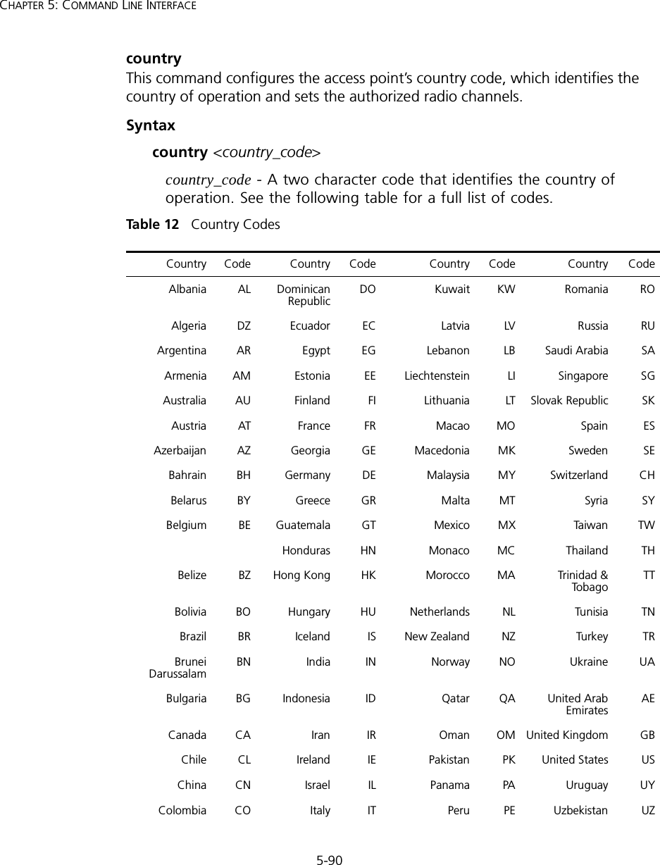
5-90CHAPTER 5: COMMAND LINE INTERFACEcountryThis command configures the access point’s country code, which identifies the country of operation and sets the authorized radio channels. Syntax country <country_code>country_code - A two character code that identifies the country of operation. See the following table for a full list of codes.Table 12   Country CodesCountry Code Country Code Country Code Country CodeAlbania AL Dominican RepublicDO Kuwait KW Romania ROAlgeria DZ Ecuador EC Latvia LV Russia RUArgentina AR Egypt EG Lebanon LB Saudi Arabia SAArmenia AM Estonia EE Liechtenstein LI Singapore SGAustralia AU Finland FI Lithuania LT Slovak Republic SKAustria AT France FR Macao MO Spain ESAzerbaijan AZ Georgia GE Macedonia MK Sweden SEBahrain BH Germany DE Malaysia MY Switzerland CHBelarus BY Greece GR Malta MT Syria SYBelgium BE Guatemala GT Mexico MX Ta iw an TWHonduras HN Monaco MC Thailand THBelize BZ Hong Kong  HK Morocco MA Trinidad & TobagoTTBolivia BO Hungary HU Netherlands NL Tunisia TNBrazil BR Iceland IS New Zealand NZ Turkey TRBrunei Darussalam BN India IN Norway NO Ukraine UABulgaria BG Indonesia ID Qatar QA United Arab EmiratesAECanada CA Iran IR Oman OM United Kingdom GBChile CL Ireland IE Pakistan PK United States USChina CN Israel IL Panama PA Uruguay UYColombia CO Italy IT Peru PE Uzbekistan UZ
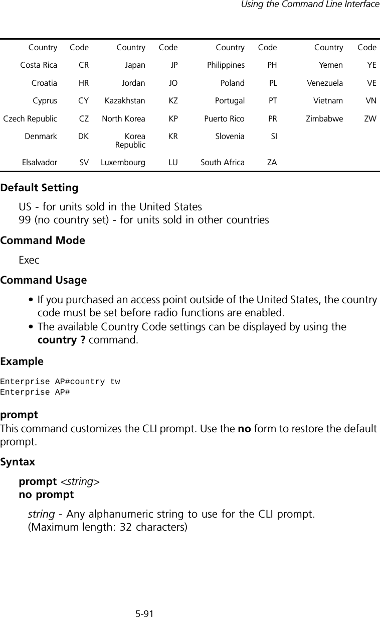
5-91Using the Command Line InterfaceDefault Setting US - for units sold in the United States 99 (no country set) - for units sold in other countriesCommand Mode ExecCommand Usage• If you purchased an access point outside of the United States, the country code must be set before radio functions are enabled.• The available Country Code settings can be displayed by using the country ? command.Example promptThis command customizes the CLI prompt. Use the no form to restore the default prompt.Syntax prompt <string> no promptstring - Any alphanumeric string to use for the CLI prompt. (Maximum length: 32 characters)Costa Rica CR Japan JP Philippines PH Yemen YECroatia HR Jordan JO Poland PL Venezuela VECyprus CY Kazakhstan KZ Portugal PT Vietnam VNCzech Republic CZ North Korea KP Puerto Rico PR Zimbabwe ZWDenmark DK Korea Republic KR Slovenia SIElsalvador SV Luxembourg LU South Africa ZAEnterprise AP#country twEnterprise AP#Country Code Country Code Country Code Country Code
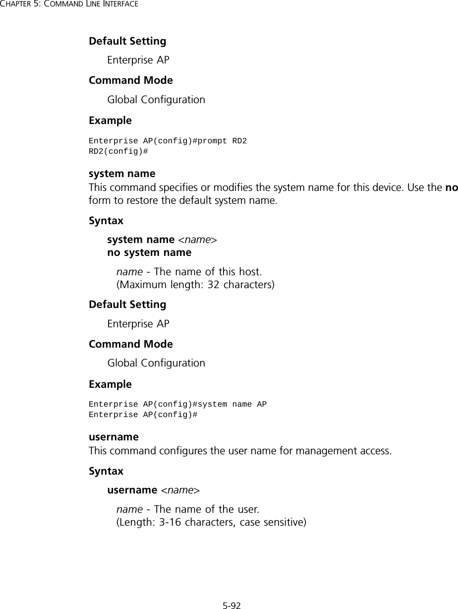
5-92CHAPTER 5: COMMAND LINE INTERFACEDefault Setting Enterprise APCommand Mode Global ConfigurationExample system nameThis command specifies or modifies the system name for this device. Use the no form to restore the default system name.Syntax system name <name> no system namename - The name of this host.  (Maximum length: 32 characters)Default Setting Enterprise APCommand Mode Global ConfigurationExample usernameThis command configures the user name for management access.Syntax username <name>name - The name of the user.  (Length: 3-16 characters, case sensitive)Enterprise AP(config)#prompt RD2RD2(config)#Enterprise AP(config)#system name APEnterprise AP(config)#
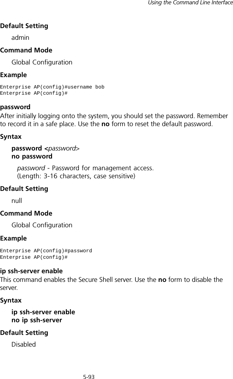
5-93Using the Command Line InterfaceDefault Setting adminCommand Mode Global ConfigurationExamplepasswordAfter initially logging onto the system, you should set the password. Remember to record it in a safe place. Use the no form to reset the default password.Syntax password <password> no passwordpassword - Password for management access. (Length: 3-16 characters, case sensitive) Default Setting nullCommand Mode Global ConfigurationExample ip ssh-server enable This command enables the Secure Shell server. Use the no form to disable the server.Syntax ip ssh-server enable no ip ssh-serverDefault Setting DisabledEnterprise AP(config)#username bobEnterprise AP(config)#Enterprise AP(config)#password Enterprise AP(config)#
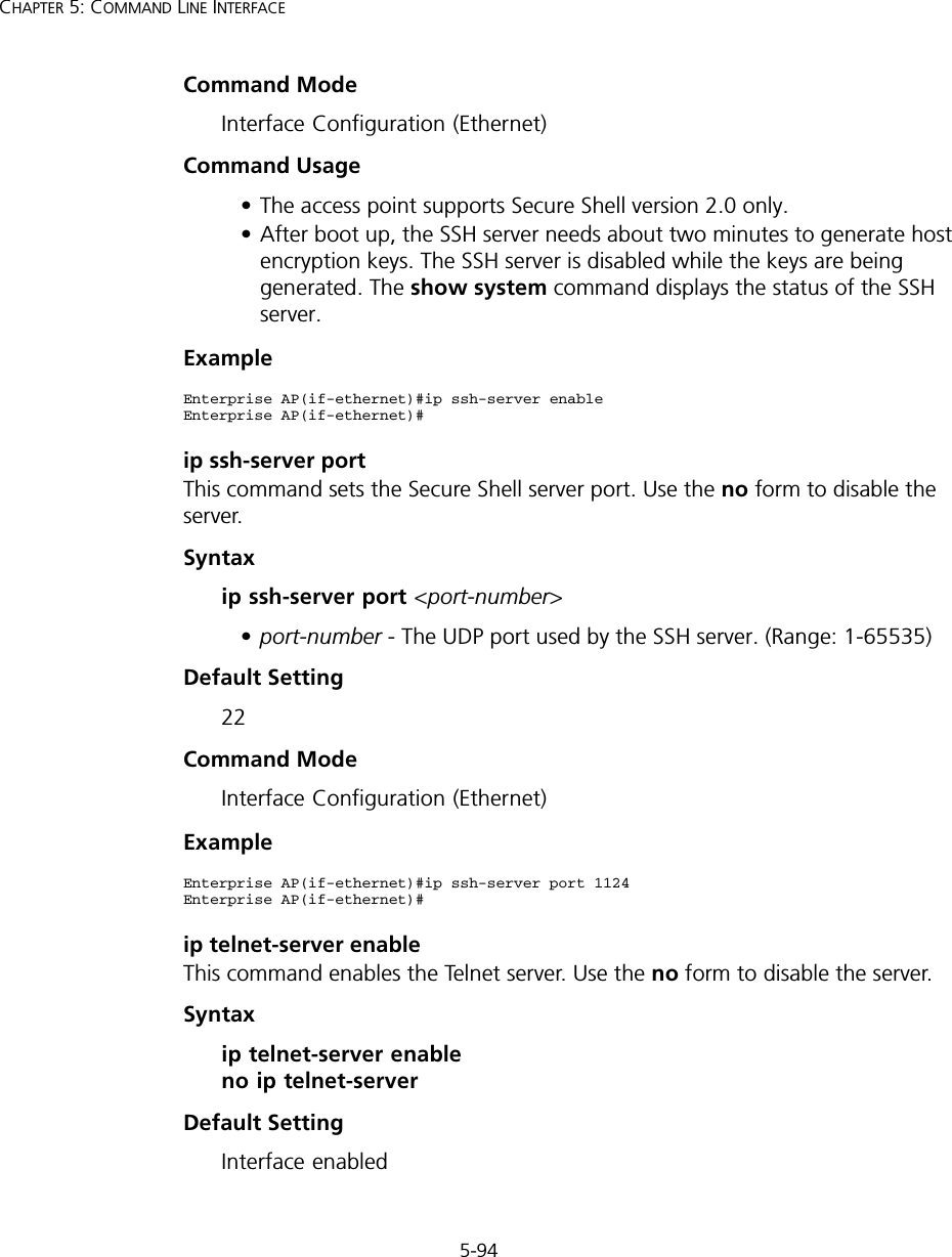
5-94CHAPTER 5: COMMAND LINE INTERFACECommand Mode Interface Configuration (Ethernet)Command Usage • The access point supports Secure Shell version 2.0 only.• After boot up, the SSH server needs about two minutes to generate host encryption keys. The SSH server is disabled while the keys are being generated. The show system command displays the status of the SSH server.Exampleip ssh-server port This command sets the Secure Shell server port. Use the no form to disable the server.Syntax ip ssh-server port <port-number>•port-number - The UDP port used by the SSH server. (Range: 1-65535)Default Setting 22Command Mode Interface Configuration (Ethernet)Exampleip telnet-server enable This command enables the Telnet server. Use the no form to disable the server.Syntax ip telnet-server enable no ip telnet-serverDefault Setting Interface enabledEnterprise AP(if-ethernet)#ip ssh-server enableEnterprise AP(if-ethernet)#Enterprise AP(if-ethernet)#ip ssh-server port 1124Enterprise AP(if-ethernet)#
5-95Using the Command Line InterfaceCommand Mode Interface Configuration (Ethernet)Exampleip http portThis command specifies the TCP port number used by the web browser interface. Use the no form to use the default port.Syntax ip http port <port-number> no ip http portport-number - The TCP port to be used by the browser interface. (Range: 1024-65535)Default Setting 80Command Mode Global ConfigurationExampleRelated Commandsip http server (5-95)ip http serverThis command allows this device to be monitored or configured from a browser. Use the no form to disable this function.Syntax [no] ip http serverDefault Setting EnabledEnterprise AP(if-ethernet)#ip telnet-server enableEnterprise AP(if-ethernet)#Enterprise AP(config)#ip http port 769Enterprise AP(config)#
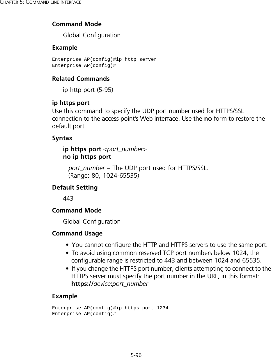
5-96CHAPTER 5: COMMAND LINE INTERFACECommand Mode Global ConfigurationExample Related Commandsip http port (5-95)ip https portUse this command to specify the UDP port number used for HTTPS/SSL connection to the access point’s Web interface. Use the no form to restore the default port.Syntax ip https port <port_number> no ip https portport_number – The UDP port used for HTTPS/SSL.  (Range: 80, 1024-65535)Default Setting 443Command Mode Global ConfigurationCommand Usage • You cannot configure the HTTP and HTTPS servers to use the same port.• To avoid using common reserved TCP port numbers below 1024, the configurable range is restricted to 443 and between 1024 and 65535. • If you change the HTTPS port number, clients attempting to connect to the HTTPS server must specify the port number in the URL, in this format: https://device:port_numberExample Enterprise AP(config)#ip http serverEnterprise AP(config)#Enterprise AP(config)#ip https port 1234Enterprise AP(config)#
5-97Using the Command Line Interfaceip https serverUse this command to enable the secure hypertext transfer protocol (HTTPS) over the Secure Socket Layer (SSL), providing secure access (i.e., an encrypted connection) to the access point’s Web interface. Use the no form to disable this function.Syntax [no] ip https serverDefault Setting DisabledCommand Mode Global ConfigurationCommand Usage • Both HTTP and HTTPS service can be enabled independently.• If you enable HTTPS, you must indicate this in the URL:  https://device:port_number]• When you start HTTPS, the connection is established in this way:- The client authenticates the server using the server’s digital certificate.- The client and server negotiate a set of security protocols to use for the connection.- The client and server generate session keys for encrypting and decrypting data.• The client and server establish a secure encrypted connection. A padlock icon should appear in the status bar for Internet Explorer 5.x.Example Enterprise AP(config)#ip https serverEnterprise AP(config)#
5-98CHAPTER 5: COMMAND LINE INTERFACEweb-redirectUse this command to enable web-based authentication of clients. Use the no form to disable this function.Syntax [no] web-redirectDefault Setting DisabledCommand Mode Global ConfigurationCommand Usage • The web redirect feature is used to support billing for a public access wireless network. After successful association to an access point, a client is “redirected” to an access point login web page as soon as Internet access is attempted. The client is then authenticated by entering a user name and password on the web page. This process allows controlled access for clients without requiring 802.1X or MAC authentication.• Web redirect requires a RADIUS server on the wired network with configured user names and passwords for authentication. The RADIUS server details must also be configured on the access point. (See “show bootfile” on page 140.)•Use the show system command to display the current web redirect status.Example Enterprise AP(config)#web-redirectEnterprise AP(config)#
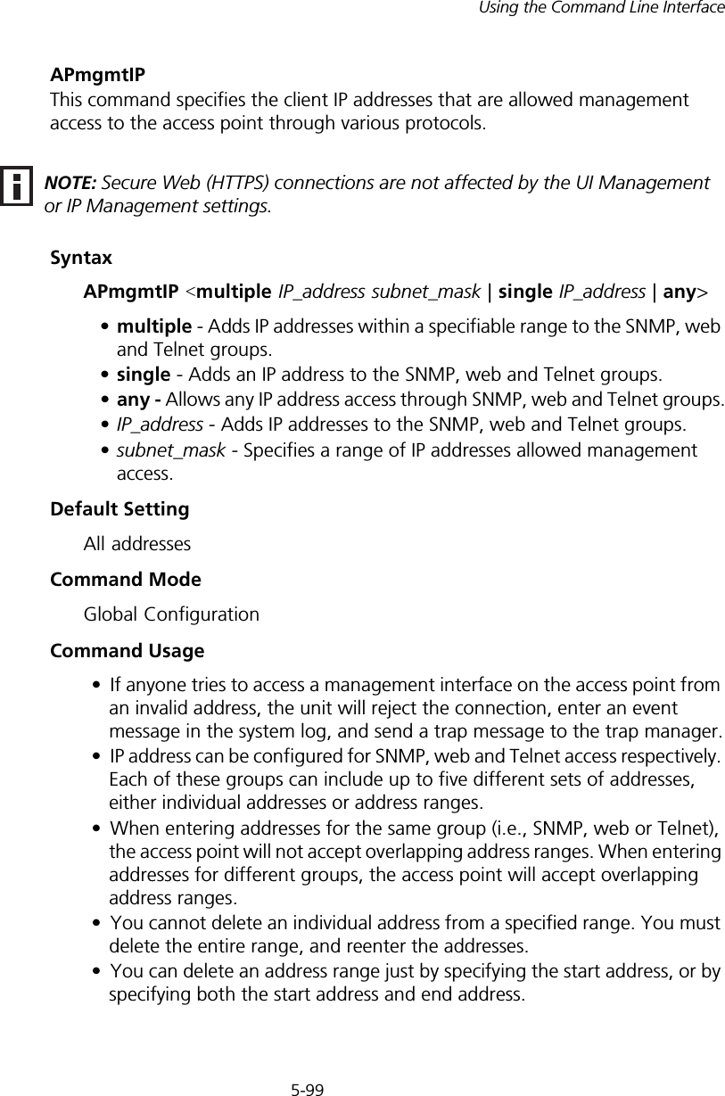
5-99Using the Command Line InterfaceAPmgmtIPThis command specifies the client IP addresses that are allowed management access to the access point through various protocols.SyntaxAPmgmtIP <multiple IP_address subnet_mask | single IP_address | any> •multiple - Adds IP addresses within a specifiable range to the SNMP, web and Telnet groups.•single - Adds an IP address to the SNMP, web and Telnet groups.•any - Allows any IP address access through SNMP, web and Telnet groups.•IP_address - Adds IP addresses to the SNMP, web and Telnet groups.•subnet_mask - Specifies a range of IP addresses allowed management access.Default SettingAll addressesCommand ModeGlobal ConfigurationCommand Usage• If anyone tries to access a management interface on the access point from an invalid address, the unit will reject the connection, enter an event message in the system log, and send a trap message to the trap manager.• IP address can be configured for SNMP, web and Telnet access respectively. Each of these groups can include up to five different sets of addresses, either individual addresses or address ranges.• When entering addresses for the same group (i.e., SNMP, web or Telnet), the access point will not accept overlapping address ranges. When entering addresses for different groups, the access point will accept overlapping address ranges.• You cannot delete an individual address from a specified range. You must delete the entire range, and reenter the addresses.• You can delete an address range just by specifying the start address, or by specifying both the start address and end address.NOTE: Secure Web (HTTPS) connections are not affected by the UI Management or IP Management settings.
5-100CHAPTER 5: COMMAND LINE INTERFACEExampleThis example restricts management access to the indicated addresses.APmgmtUIThis command enables and disables management access to the access point through SNMP, Telnet and web interfaces.SyntaxAPmgmtUI <[SNMP | Te l net   | Web] enable | disable>•SNMP - Specifies SNMP management access.•Telnet - Specifies Telnet management access.•Web - Specifies web based management access.-enable/disable - Enables or disables the selected management access method.Default SettingAll enabledCommand ModeGlobal ConfigurationExampleThis example restricts management access to the indicated addresses.Enterprise AP(config)#apmgmtip multiple 192.254.1.50 255.255.255.0Enterprise AP(config)#NOTE: Secure Web (HTTPS) connections are not affected by the UI Management or IP Management settings.Enterprise AP(config)#apmgmtui SNMP enableEnterprise AP(config)#
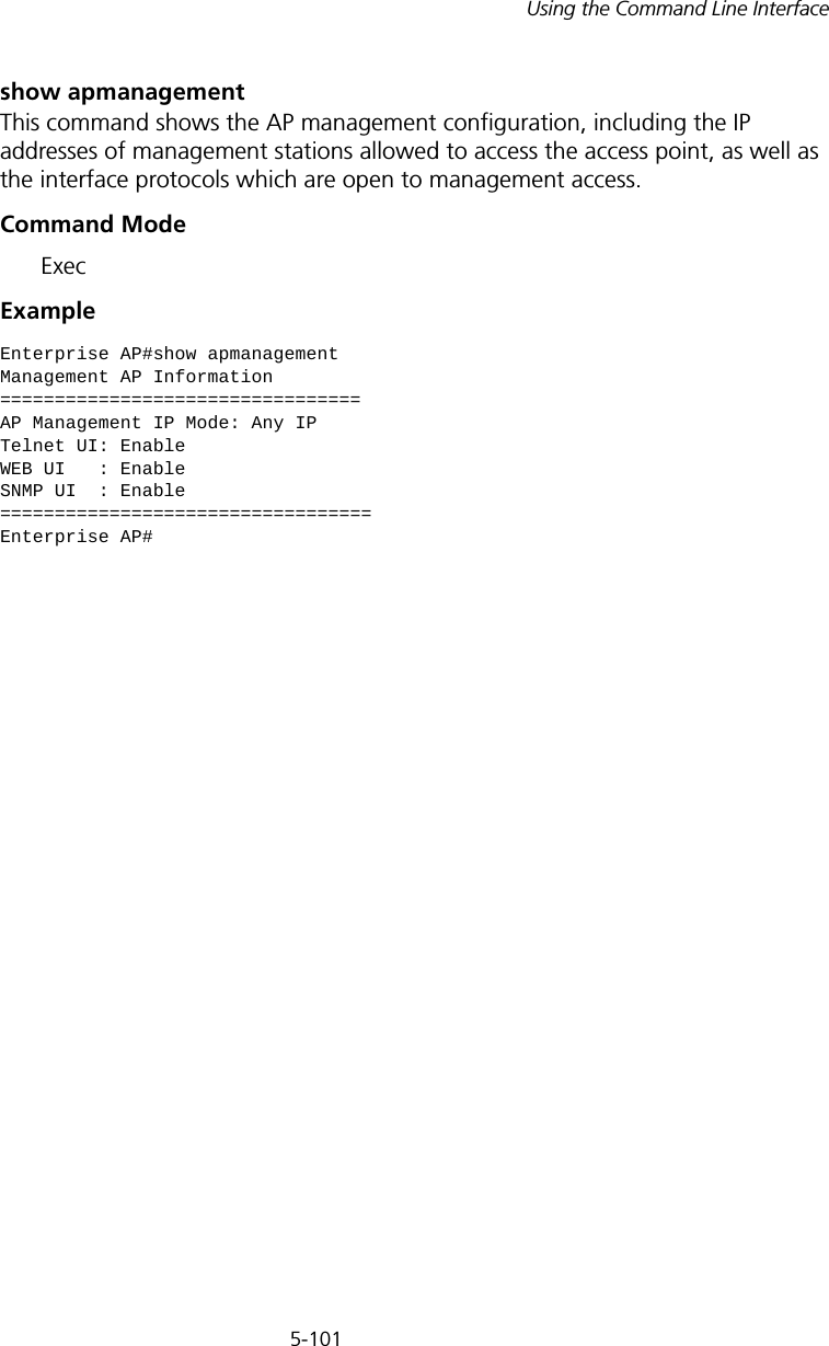
5-101Using the Command Line Interfaceshow apmanagementThis command shows the AP management configuration, including the IP addresses of management stations allowed to access the access point, as well as the interface protocols which are open to management access.Command Mode ExecExampleEnterprise AP#show apmanagementManagement AP Information=================================AP Management IP Mode: Any IPTelnet UI: EnableWEB UI   : EnableSNMP UI  : Enable==================================Enterprise AP#
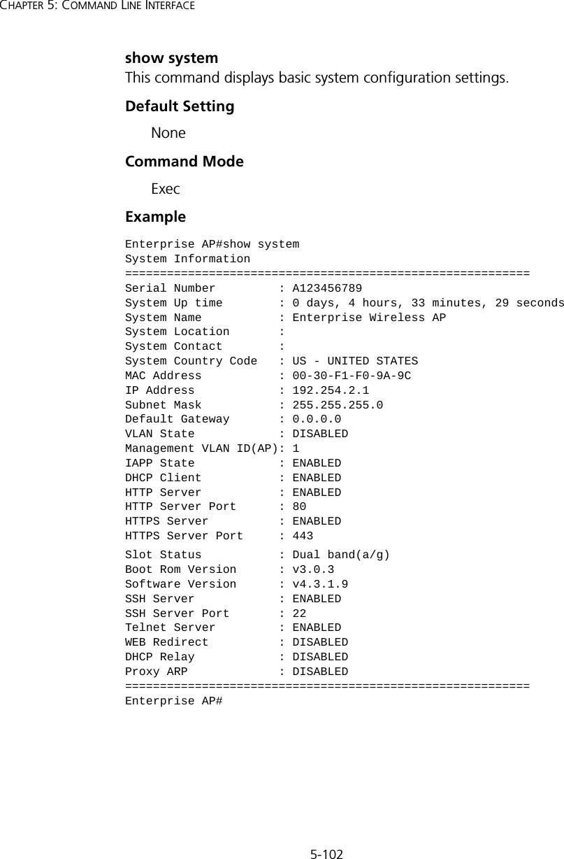
5-102CHAPTER 5: COMMAND LINE INTERFACEshow systemThis command displays basic system configuration settings.Default SettingNoneCommand Mode ExecExampleEnterprise AP#show systemSystem Information==========================================================Serial Number         : A123456789System Up time        : 0 days, 4 hours, 33 minutes, 29 secondsSystem Name           : Enterprise Wireless APSystem Location       :System Contact        :System Country Code   : US - UNITED STATESMAC Address           : 00-30-F1-F0-9A-9CIP Address            : 192.254.2.1Subnet Mask           : 255.255.255.0Default Gateway       : 0.0.0.0VLAN State            : DISABLEDManagement VLAN ID(AP): 1IAPP State            : ENABLEDDHCP Client           : ENABLEDHTTP Server           : ENABLEDHTTP Server Port      : 80HTTPS Server          : ENABLEDHTTPS Server Port     : 443Slot Status           : Dual band(a/g)Boot Rom Version      : v3.0.3Software Version      : v4.3.1.9SSH Server            : ENABLEDSSH Server Port       : 22Telnet Server         : ENABLEDWEB Redirect          : DISABLEDDHCP Relay            : DISABLEDProxy ARP             : DISABLED==========================================================Enterprise AP#
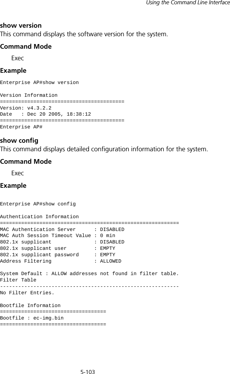
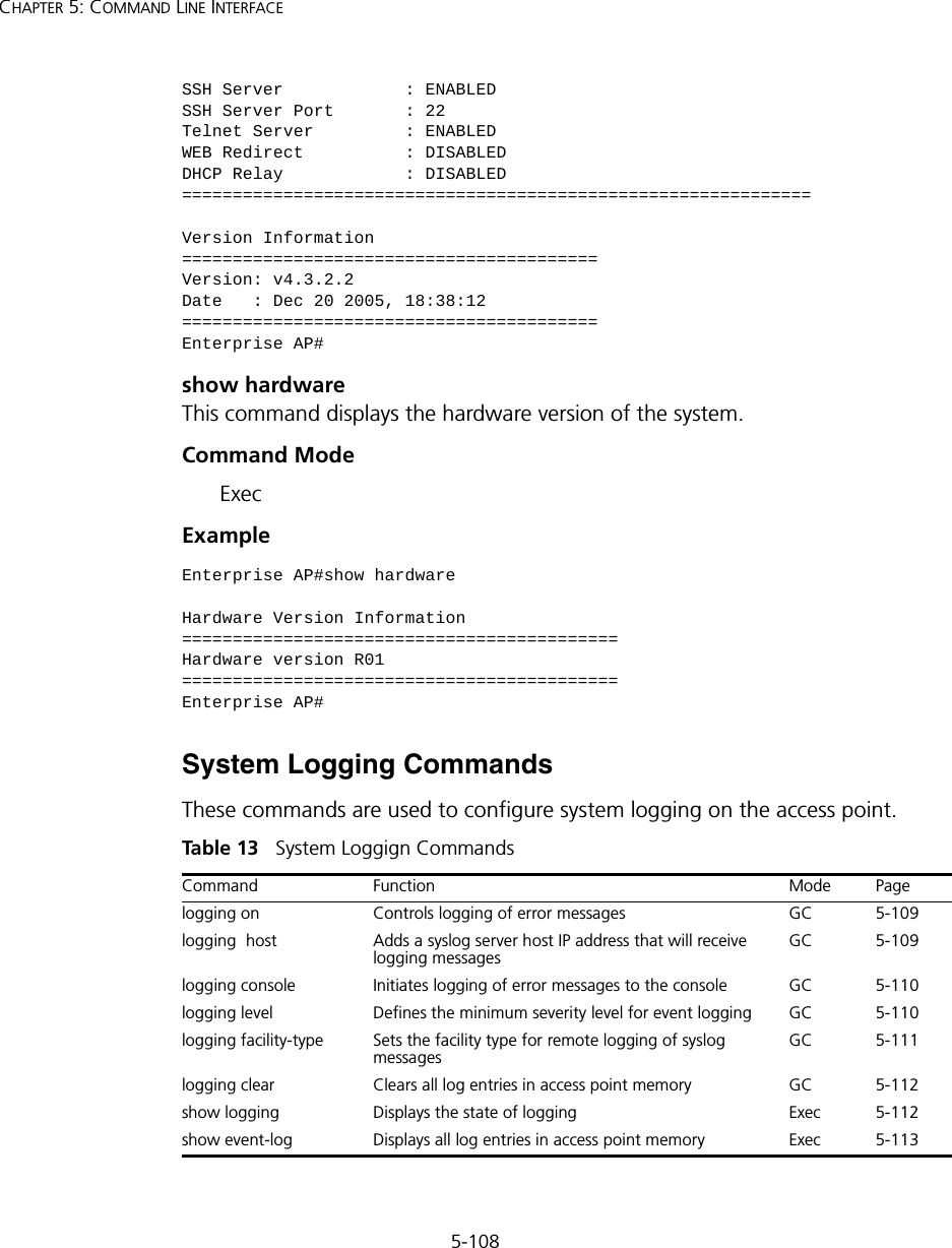
5-103Using the Command Line Interfaceshow versionThis command displays the software version for the system.Command Mode ExecExample show configThis command displays detailed configuration information for the system.Command Mode ExecExample Enterprise AP#show versionVersion Information=========================================Version: v4.3.2.2Date   : Dec 20 2005, 18:38:12=========================================Enterprise AP#Enterprise AP#show configAuthentication Information===========================================================MAC Authentication Server      : DISABLEDMAC Auth Session Timeout Value : 0 min802.1x supplicant              : DISABLED802.1x supplicant user         : EMPTY802.1x supplicant password     : EMPTYAddress Filtering              : ALLOWEDSystem Default : ALLOW addresses not found in filter table.Filter Table-----------------------------------------------------------No Filter Entries.Bootfile Information===================================Bootfile : ec-img.bin===================================
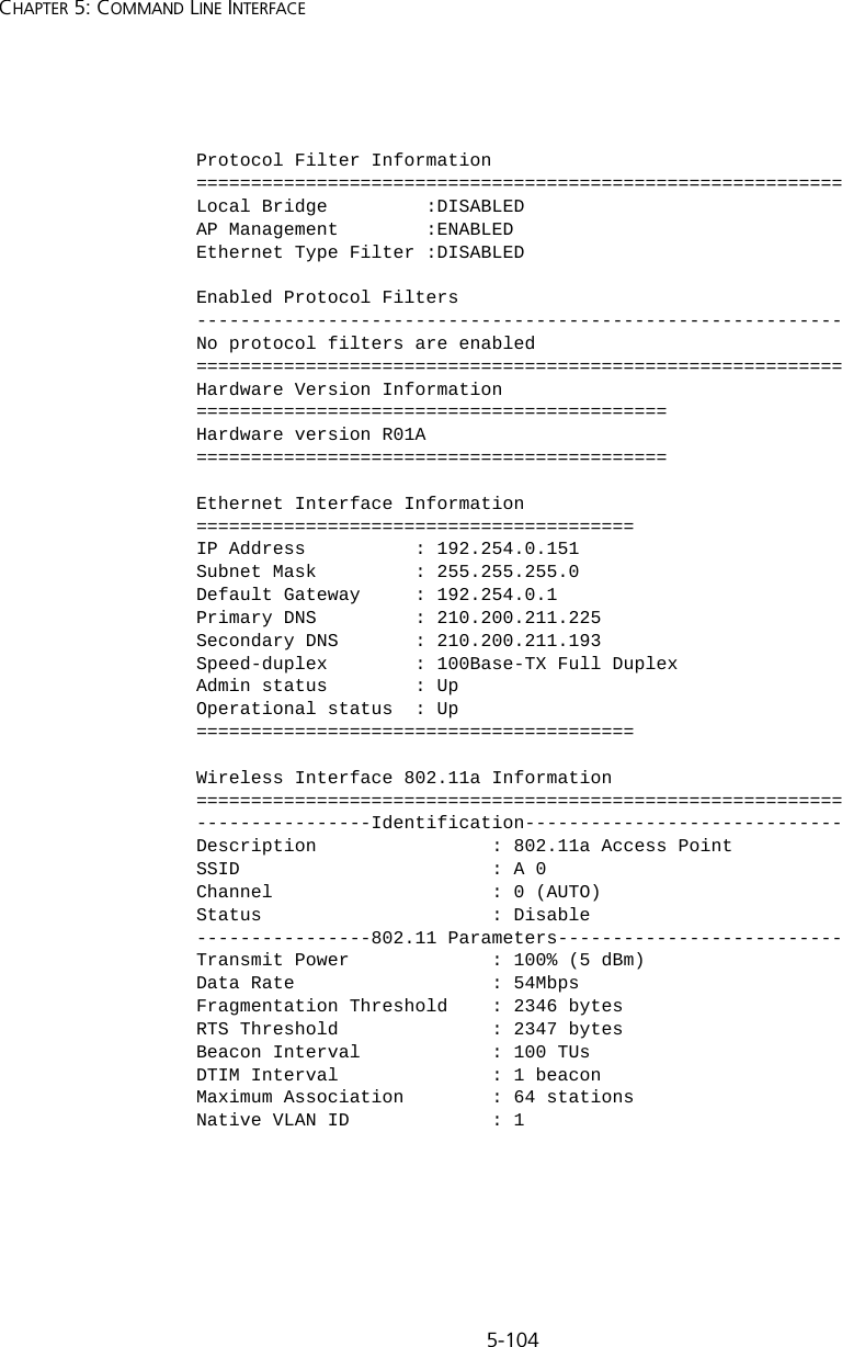
5-104CHAPTER 5: COMMAND LINE INTERFACEProtocol Filter Information===========================================================Local Bridge         :DISABLEDAP Management        :ENABLEDEthernet Type Filter :DISABLEDEnabled Protocol Filters-----------------------------------------------------------No protocol filters are enabled===========================================================Hardware Version Information===========================================Hardware version R01A===========================================Ethernet Interface Information========================================IP Address          : 192.254.0.151Subnet Mask         : 255.255.255.0Default Gateway     : 192.254.0.1Primary DNS         : 210.200.211.225Secondary DNS       : 210.200.211.193Speed-duplex        : 100Base-TX Full DuplexAdmin status        : UpOperational status  : Up========================================Wireless Interface 802.11a Information===========================================================----------------Identification-----------------------------Description                : 802.11a Access PointSSID                       : A 0Channel                    : 0 (AUTO)Status                     : Disable----------------802.11 Parameters--------------------------Transmit Power             : 100% (5 dBm)Data Rate                  : 54MbpsFragmentation Threshold    : 2346 bytesRTS Threshold              : 2347 bytesBeacon Interval            : 100 TUsDTIM Interval              : 1 beaconMaximum Association        : 64 stationsNative VLAN ID             : 1
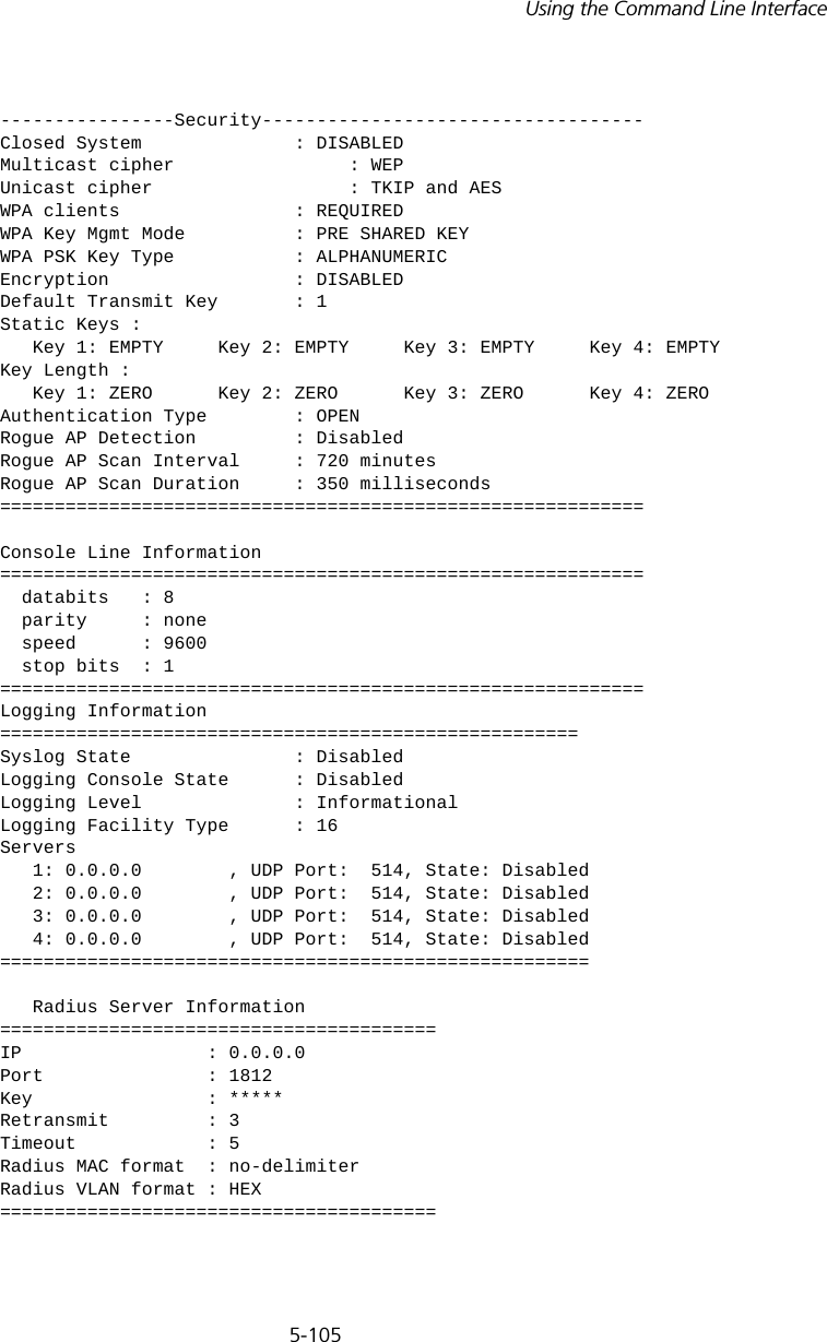
5-105Using the Command Line Interface----------------Security-----------------------------------Closed System              : DISABLEDMulticast cipher                : WEPUnicast cipher                  : TKIP and AESWPA clients                : REQUIREDWPA Key Mgmt Mode          : PRE SHARED KEYWPA PSK Key Type           : ALPHANUMERICEncryption                 : DISABLEDDefault Transmit Key       : 1Static Keys :    Key 1: EMPTY     Key 2: EMPTY     Key 3: EMPTY     Key 4: EMPTY  Key Length :    Key 1: ZERO      Key 2: ZERO      Key 3: ZERO      Key 4: ZERO   Authentication Type        : OPENRogue AP Detection         : DisabledRogue AP Scan Interval     : 720 minutesRogue AP Scan Duration     : 350 milliseconds===========================================================Console Line Information===========================================================  databits   : 8  parity     : none   speed      : 9600  stop bits  : 1===========================================================Logging Information=====================================================Syslog State               : DisabledLogging Console State      : DisabledLogging Level              : InformationalLogging Facility Type      : 16Servers   1: 0.0.0.0        , UDP Port:  514, State: Disabled   2: 0.0.0.0        , UDP Port:  514, State: Disabled   3: 0.0.0.0        , UDP Port:  514, State: Disabled   4: 0.0.0.0        , UDP Port:  514, State: Disabled======================================================   Radius Server Information========================================IP                 : 0.0.0.0Port               : 1812Key                : *****Retransmit         : 3Timeout            : 5Radius MAC format  : no-delimiterRadius VLAN format : HEX========================================
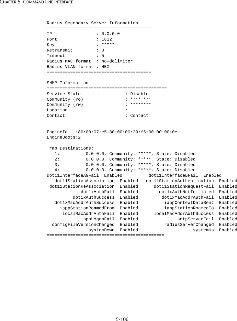
5-106CHAPTER 5: COMMAND LINE INTERFACERadius Secondary Server Information========================================IP                 : 0.0.0.0Port               : 1812Key                : *****Retransmit         : 3Timeout            : 5Radius MAC format  : no-delimiterRadius VLAN format : HEX========================================SNMP Information==============================================Service State                 : DisableCommunity (ro)                : ********Community (rw)                : ********Location                      : Contact                       : ContactEngineId   :80:00:07:e5:80:00:00:29:f6:00:00:00:0cEngineBoots:2Trap Destinations:   1:          0.0.0.0, Community: *****, State: Disabled   2:          0.0.0.0, Community: *****, State: Disabled   3:          0.0.0.0, Community: *****, State: Disabled   4:          0.0.0.0, Community: *****, State: Disableddot11InterfaceAGFail  Enabled          dot11InterfaceBFail  Enabled   dot11StationAssociation  Enabled   dot11StationAuthentication  Enabled dot11StationReAssociation  Enabled      dot11StationRequestFail  Enabled             dot1xAuthFail  Enabled        dot1xAuthNotInitiated  Enabled          dot1xAuthSuccess  Enabled         dot1xMacAddrAuthFail  Enabled   dot1xMacAddrAuthSuccess  Enabled          iappContextDataSent  Enabled     iappStationRoamedFrom  Enabled          iappStationRoamedTo  Enabled      localMacAddrAuthFail  Enabled      localMacAddrAuthSuccess  Enabled              pppLogonFail  Enabled               sntpServerFail  Enabled  configFileVersionChanged  Enabled          radiusServerChanged  Enabled                systemDown  Enabled                     systemUp  Enabled=============================================
5-107Using the Command Line InterfaceSNTP Information===========================================================Service State        : DisabledSNTP (server 1) IP   : 137.92.140.80SNTP (server 2) IP   : 192.43.244.18Current Time         : 00 : 14, Jan 1st, 1970Time Zone            : -5 (BOGOTA, EASTERN, INDIANA)Daylight Saving      : Disabled===========================================================Station Table Information===========================================================if-wireless A VAP [0]   : 802.11a Channel : AutoNo 802.11a Channel Stations....if-wireless G VAP [0]   : 802.11g Channel : AutoNo 802.11g Channel Stations....System Information==============================================================Serial Number         :  System Up time        : 0 days, 0 hours, 16 minutes, 51 secondsSystem Name           : Enterprise Wireless APSystem Location       : System Contact        : ContactSystem Country Code   : 99 - NO_COUNTRY_SET MAC Address           : 00-12-CF-05-B7-84IP Address            : 192.254.0.151Subnet Mask           : 255.255.255.0Default Gateway       : 192.254.0.1VLAN State            : DISABLEDManagement VLAN ID(AP): 1IAPP State            : ENABLEDDHCP Client           : ENABLEDHTTP Server           : ENABLEDHTTP Server Port      : 80HTTPS Server          : ENABLEDHTTPS Server Port     : 443Slot Status           : Dual band(a/g)Boot Rom Version      : v3.0.7Software Version      : v4.3.2.2
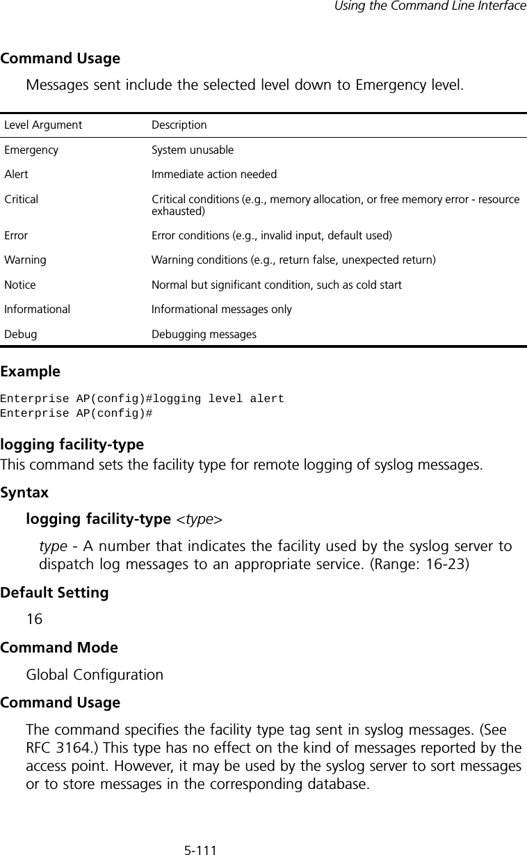
5-108CHAPTER 5: COMMAND LINE INTERFACEshow hardwareThis command displays the hardware version of the system.Command Mode ExecExample System Logging CommandsThese commands are used to configure system logging on the access point.Tabl e  13   System Loggign CommandsSSH Server            : ENABLEDSSH Server Port       : 22Telnet Server         : ENABLEDWEB Redirect          : DISABLEDDHCP Relay            : DISABLED==============================================================Version Information=========================================Version: v4.3.2.2Date   : Dec 20 2005, 18:38:12=========================================Enterprise AP#Enterprise AP#show hardwareHardware Version Information===========================================Hardware version R01===========================================Enterprise AP#Command Function Mode Pagelogging on  Controls logging of error messages GC 5-109logging  host Adds a syslog server host IP address that will receive logging messages  GC 5-109logging console Initiates logging of error messages to the console GC 5-110logging level Defines the minimum severity level for event logging GC 5-110logging facility-type Sets the facility type for remote logging of syslog messages GC 5-111logging clear Clears all log entries in access point memory GC 5-112show logging  Displays the state of logging Exec 5-112show event-log Displays all log entries in access point memory Exec 5-113
5-109Using the Command Line Interfacelogging onThis command controls logging of error messages; i.e., sending debug or error messages to memory. The no form disables the logging process.Syntax[no] logging onDefault SettingDisabledCommand Mode Global ConfigurationCommand Usage The logging process controls error messages saved to memory. You can use the logging level command to control the type of error messages that are stored in memory. Example logging hostThis command specifies syslog servers host that will receive logging messages. Use the no form to remove syslog server host.Syntaxlogging host <1 | 2 | 3 | 4> <host_name | host_ip_address> [udp_port] no logging host <1 | 2 | 3 | 4>•1 - First syslog server.•2 - Second syslog server.•3 - Third syslog server.•4 - Fourth syslog server.•host_name - The name of a syslog server. (Range: 1-20 characters)•host_ip_address - The IP address of a syslog server.•udp_port - The UDP port used by the syslog server.Enterprise AP(config)#logging onEnterprise AP(config)#
5-110CHAPTER 5: COMMAND LINE INTERFACEDefault Setting NoneCommand Mode Global ConfigurationExample logging consoleThis command initiates logging of error messages to the console. Use the no form to disable logging to the console.Syntax[no] logging consoleDefault Setting DisabledCommand Mode Global ConfigurationExample logging levelThis command sets the minimum severity level for event logging.Syntaxlogging level <Emergency | Alert | Critical | Error | Warning | Notice | Informational | Debug>Default Setting InformationalCommand Mode Global ConfigurationEnterprise AP(config)#logging host 1 10.1.0.3Enterprise AP(config)#Enterprise AP(config)#logging consoleEnterprise AP(config)#
5-111Using the Command Line InterfaceCommand Usage Messages sent include the selected level down to Emergency level.Example logging facility-typeThis command sets the facility type for remote logging of syslog messages.Syntaxlogging facility-type <type>type - A number that indicates the facility used by the syslog server to dispatch log messages to an appropriate service. (Range: 16-23)Default Setting 16Command Mode Global ConfigurationCommand Usage The command specifies the facility type tag sent in syslog messages. (See RFC 3164.) This type has no effect on the kind of messages reported by the access point. However, it may be used by the syslog server to sort messages or to store messages in the corresponding database.Level Argument DescriptionEmergency System unusableAlert Immediate action neededCritical Critical conditions (e.g., memory allocation, or free memory error - resource exhausted)Error Error conditions (e.g., invalid input, default used)Warning Warning conditions (e.g., return false, unexpected return)Notice Normal but significant condition, such as cold start Informational Informational messages onlyDebug Debugging messagesEnterprise AP(config)#logging level alertEnterprise AP(config)#
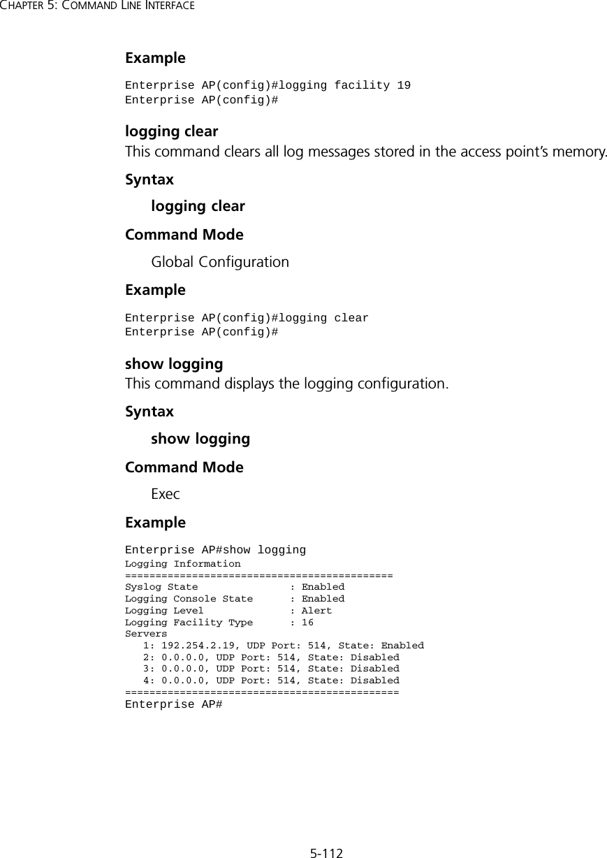
5-112CHAPTER 5: COMMAND LINE INTERFACEExample logging clearThis command clears all log messages stored in the access point’s memory.Syntaxlogging clearCommand Mode Global ConfigurationExample show loggingThis command displays the logging configuration.Syntaxshow loggingCommand Mode ExecExampleEnterprise AP(config)#logging facility 19Enterprise AP(config)#Enterprise AP(config)#logging clearEnterprise AP(config)#Enterprise AP#show loggingLogging Information============================================Syslog State               : EnabledLogging Console State      : EnabledLogging Level              : AlertLogging Facility Type      : 16Servers   1: 192.254.2.19, UDP Port: 514, State: Enabled   2: 0.0.0.0, UDP Port: 514, State: Disabled   3: 0.0.0.0, UDP Port: 514, State: Disabled   4: 0.0.0.0, UDP Port: 514, State: Disabled=============================================Enterprise AP#
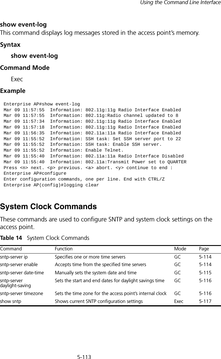
5-113Using the Command Line Interfaceshow event-logThis command displays log messages stored in the access point’s memory.Syntaxshow event-logCommand Mode ExecExampleSystem Clock CommandsThese commands are used to configure SNTP and system clock settings on the access point.Tabl e  14   System Clock CommandsEnterprise AP#show event-logMar 09 11:57:55  Information: 802.11g:11g Radio Interface EnabledMar 09 11:57:55  Information: 802.11g:Radio channel updated to 8Mar 09 11:57:34  Information: 802.11g:11g Radio Interface EnabledMar 09 11:57:18  Information: 802.11g:11g Radio Interface EnabledMar 09 11:56:35  Information: 802.11a:11a Radio Interface EnabledMar 09 11:55:52  Information: SSH task: Set SSH server port to 22Mar 09 11:55:52  Information: SSH task: Enable SSH server.Mar 09 11:55:52  Information: Enable Telnet.Mar 09 11:55:40  Information: 802.11a:11a Radio Interface DisabledMar 09 11:55:40  Information: 802.11a:Transmit Power set to QUARTERPress <n> next. <p> previous. <a> abort. <y> continue to end :Enterprise AP#configureEnter configuration commands, one per line. End with CTRL/ZEnterprise AP(config)#logging clearCommand Function Mode Pagesntp-server ip Specifies one or more time servers GC 5-114sntp-server enable  Accepts time from the specified time servers GC 5-114sntp-server date-time Manually sets the system date and time GC 5-115sntp-server daylight-savingSets the start and end dates for daylight savings time GC 5-116sntp-server timezone Sets the time zone for the access point’s internal clock GC 5-116show sntp Shows current SNTP configuration settings Exec  5-117
5-114CHAPTER 5: COMMAND LINE INTERFACEsntp-server ipThis command sets the IP address of the servers to which SNTP time requests are issued. Use the this command with no arguments to clear all time servers from the current list.Syntaxsntp-server ip <1 | 2> <ip>•1 - First time server.•2 - Second time server.•ip - IP address of an time server (NTP or SNTP). Default Setting 137.92.140.80 192.43.244.18Command Mode Global ConfigurationCommand Usage When SNTP client mode is enabled using the sntp-server enable command, the sntp-server ip command specifies the time servers from which the access point polls for time updates. The access point will poll the time servers in the order specified until a response is received. Example Related Commandssntp-server enable (5-114) show sntp (5-117)sntp-server enableThis command enables SNTP client requests for time synchronization with NTP or SNTP time servers specified by the sntp-server ip command. Use the no form to disable SNTP client requests.Syntax[no] sntp-server enable Enterprise AP(config)#sntp-server ip 10.1.0.19Enterprise AP#
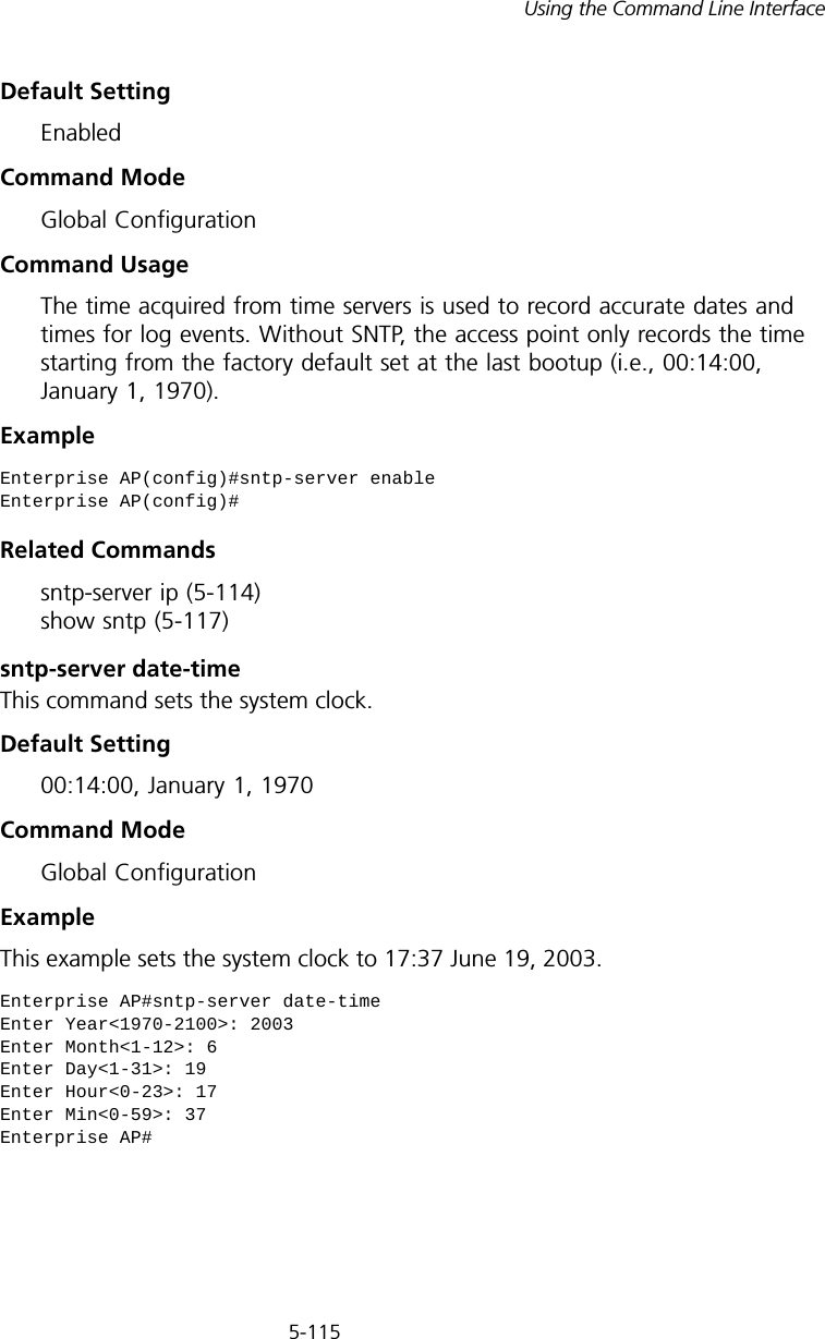
5-115Using the Command Line InterfaceDefault Setting EnabledCommand Mode Global ConfigurationCommand Usage The time acquired from time servers is used to record accurate dates and times for log events. Without SNTP, the access point only records the time starting from the factory default set at the last bootup (i.e., 00:14:00, January 1, 1970).Example Related Commandssntp-server ip (5-114) show sntp (5-117)sntp-server date-timeThis command sets the system clock.Default Setting 00:14:00, January 1, 1970Command Mode Global ConfigurationExample This example sets the system clock to 17:37 June 19, 2003.Enterprise AP(config)#sntp-server enableEnterprise AP(config)#Enterprise AP#sntp-server date-timeEnter Year<1970-2100>: 2003Enter Month<1-12>: 6Enter Day<1-31>: 19Enter Hour<0-23>: 17Enter Min<0-59>: 37Enterprise AP#
5-116CHAPTER 5: COMMAND LINE INTERFACERelated Commandssntp-server enable (5-114)sntp-server daylight-savingThis command sets the start and end dates for daylight savings time. Use the no form to disable daylight savings time.Syntax[no] sntp-server daylight-saving Default Setting DisabledCommand Mode Global ConfigurationCommand Usage The command sets the system clock back one hour during the specified period.Example This sets daylight savings time to be used from July 1st to September 1st.sntp-server timezoneThis command sets the time zone for the access point’s internal clock.Syntaxsntp-server timezone <hours>hours - Number of hours before/after UTC.  (Range: -12 to +12 hours)Default Setting -5 (BOGOTA, EASTERN, INDIANA)Enterprise AP(config)#sntp-server daylight-savingEnter Daylight saving from which month<1-12>: 6and which day<1-31>: 1Enter Daylight saving end to which month<1-12>: 9and which day<1-31>: 1Enterprise AP(config)#
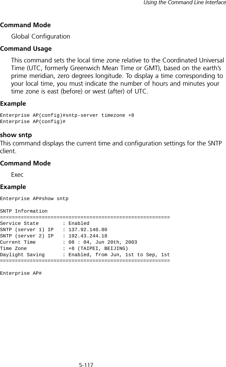
5-117Using the Command Line InterfaceCommand Mode Global ConfigurationCommand Usage This command sets the local time zone relative to the Coordinated Universal Time (UTC, formerly Greenwich Mean Time or GMT), based on the earth’s prime meridian, zero degrees longitude. To display a time corresponding to your local time, you must indicate the number of hours and minutes your time zone is east (before) or west (after) of UTC.Example show sntpThis command displays the current time and configuration settings for the SNTP client.Command ModeExecExample Enterprise AP(config)#sntp-server timezone +8Enterprise AP(config)#Enterprise AP#show sntpSNTP Information=========================================================Service State        : EnabledSNTP (server 1) IP   : 137.92.140.80SNTP (server 2) IP   : 192.43.244.18Current Time         : 08 : 04, Jun 20th, 2003Time Zone            : +8 (TAIPEI, BEIJING)Daylight Saving      : Enabled, from Jun, 1st to Sep, 1st=========================================================Enterprise AP#
5-118CHAPTER 5: COMMAND LINE INTERFACEDHCP Relay CommandsDynamic Host Configuration Protocol (DHCP) can dynamically allocate an IP address and other configuration information to network clients that broadcast a request. To receive the broadcast request, the DHCP server would normally have to be on the same subnet as the client. However, when the access point’s DHCP relay agent is enabled, received client requests can be forwarded directly by the access point to a known DHCP server on another subnet. Responses from the DHCP server are returned to the access point, which then broadcasts them back to clients.Tabl e  15   DHCP Relay Commandsdhcp-relay enableThis command enables the access point’s DHCP relay agent. Use the no form to disable the agent.Syntax[no] dhcp-relay enableDefault Setting DisabledCommand Mode Global ConfigurationCommand Usage • For the DHCP relay agent to function, the primary DHCP server must be configured using the dhcp-relay primary command. A secondary DHCP server does not need to be configured, but it is recommended.• If there is no response from the primary DHCP server, and a secondary server has been configured, the agent will then attempt to send DHCP requests to the secondary server.Example Command Function Mode Pagedhcp-relay enable Enables the DHCP relay agent GC 5-118dhcp-relay Sets the primary and secondary DHCP server addressGC 5-119show dhcp-relay Shows current DHCP relay configuration settingsExec  5-119Enterprise AP(config)#dhcp-relay enableEnterprise AP(config)#
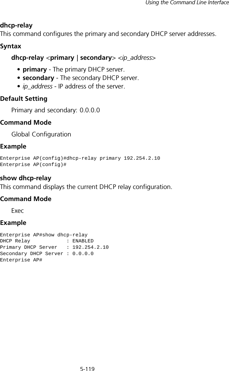
5-119Using the Command Line Interfacedhcp-relayThis command configures the primary and secondary DHCP server addresses.Syntaxdhcp-relay <primary | secondary> <ip_address>•primary - The primary DHCP server.•secondary - The secondary DHCP server.•ip_address - IP address of the server.Default Setting Primary and secondary: 0.0.0.0Command Mode Global ConfigurationExample show dhcp-relayThis command displays the current DHCP relay configuration.Command Mode ExecExample Enterprise AP(config)#dhcp-relay primary 192.254.2.10Enterprise AP(config)#Enterprise AP#show dhcp-relayDHCP Relay            : ENABLEDPrimary DHCP Server   : 192.254.2.10Secondary DHCP Server : 0.0.0.0Enterprise AP#
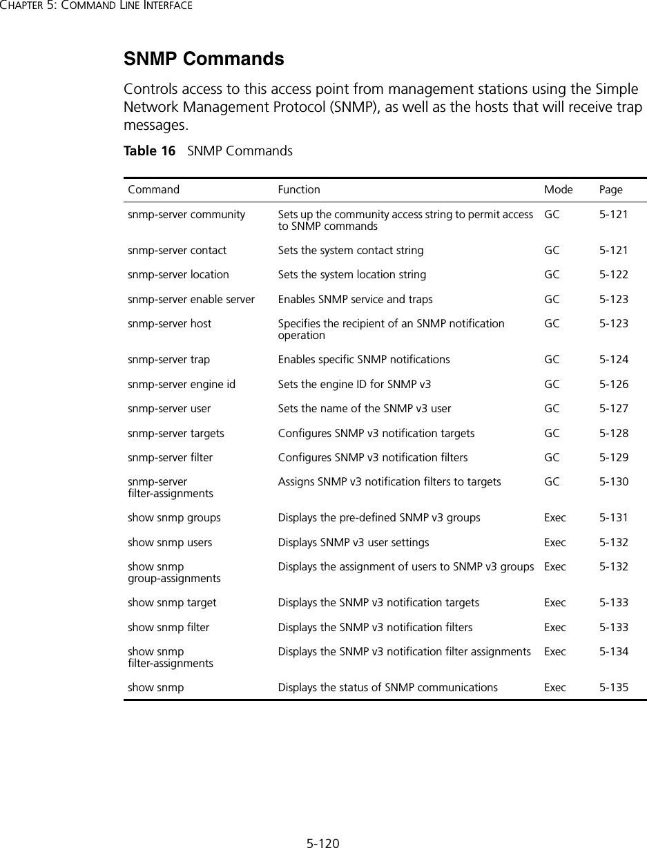
5-120CHAPTER 5: COMMAND LINE INTERFACESNMP CommandsControls access to this access point from management stations using the Simple Network Management Protocol (SNMP), as well as the hosts that will receive trap messages.Tabl e  16   SNMP CommandsCommand Function Mode Pagesnmp-server community Sets up the community access string to permit access to SNMP commands GC 5-121snmp-server contact  Sets the system contact string GC 5-121snmp-server location  Sets the system location string  GC 5-122snmp-server enable server  Enables SNMP service and traps GC 5-123snmp-server host  Specifies the recipient of an SNMP notification operation GC 5-123snmp-server trap Enables specific SNMP notifications GC 5-124snmp-server engine id Sets the engine ID for SNMP v3 GC 5-126snmp-server user Sets the name of the SNMP v3 user GC 5-127snmp-server targets Configures SNMP v3 notification targets GC 5-128snmp-server filter Configures SNMP v3 notification filters GC 5-129snmp-server filter-assignmentsAssigns SNMP v3 notification filters to targets GC 5-130show snmp groups Displays the pre-defined SNMP v3 groups Exec 5-131show snmp users Displays SNMP v3 user settings Exec 5-132show snmp group-assignments Displays the assignment of users to SNMP v3 groups Exec 5-132show snmp target Displays the SNMP v3 notification targets Exec 5-133show snmp filter Displays the SNMP v3 notification filters Exec 5-133show snmp filter-assignmentsDisplays the SNMP v3 notification filter assignments Exec 5-134show snmp Displays the status of SNMP communications Exec  5-135
5-121Using the Command Line Interfacesnmp-server communityThis command defines the community access string for the Simple Network Management Protocol. Use the no form to remove the specified community string.Syntaxsnmp-server community string [ro | rw] no snmp-server community string•string - Community string that acts like a password and permits access to the SNMP protocol. (Maximum length: 23 characters, case sensitive)•ro - Specifies read-only access. Authorized management stations are only able to retrieve MIB objects. •rw - Specifies read/write access. Authorized management stations are able to both retrieve and modify MIB objects.Default Setting • public - Read-only access. Authorized management stations are only able to retrieve MIB objects.• private - Read/write access. Authorized management stations are able to both retrieve and modify MIB objects.Command Mode Global ConfigurationCommand Usage If you enter a community string without the ro or rw option, the default is read only.Example snmp-server contactThis command sets the system contact string. Use the no form to remove the system contact information.Syntaxsnmp-server contact string no snmp-server contactstring - String that describes the system contact. (Maximum length: 255 characters)Enterprise AP(config)#snmp-server community alpha rwEnterprise AP(config)#
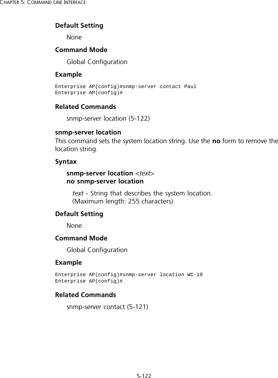
5-122CHAPTER 5: COMMAND LINE INTERFACEDefault Setting NoneCommand Mode Global ConfigurationExample Related Commandssnmp-server location (5-122)snmp-server locationThis command sets the system location string. Use the no form to remove the location string.Syntaxsnmp-server location <text> no snmp-server locationtext - String that describes the system location. (Maximum length: 255 characters)Default Setting NoneCommand Mode Global ConfigurationExample Related Commandssnmp-server contact (5-121)Enterprise AP(config)#snmp-server contact PaulEnterprise AP(config)#Enterprise AP(config)#snmp-server location WC-19Enterprise AP(config)#
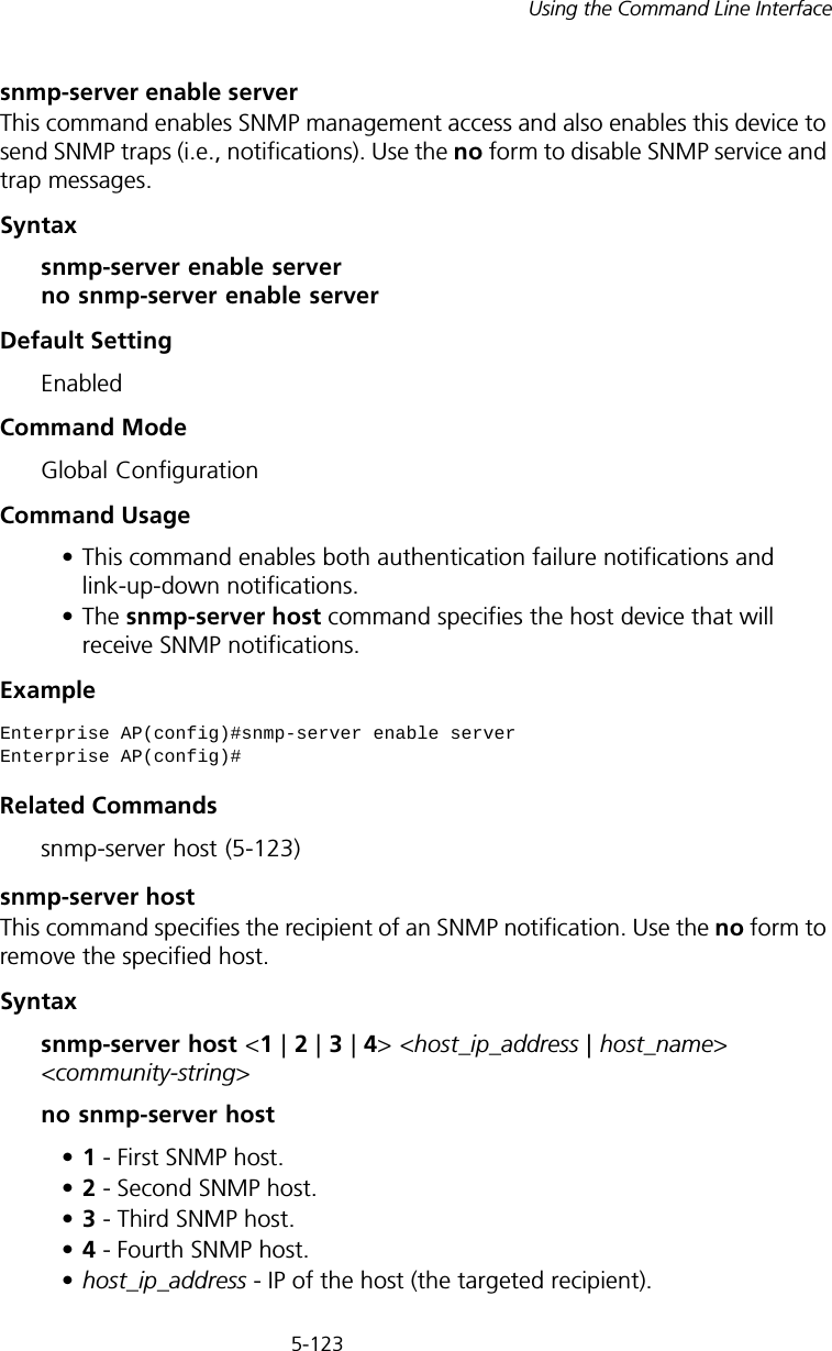
5-123Using the Command Line Interfacesnmp-server enable serverThis command enables SNMP management access and also enables this device to send SNMP traps (i.e., notifications). Use the no form to disable SNMP service and trap messages.Syntax snmp-server enable server no snmp-server enable serverDefault Setting EnabledCommand Mode Global ConfigurationCommand Usage • This command enables both authentication failure notifications and link-up-down notifications. •The snmp-server host command specifies the host device that will receive SNMP notifications. Example Related Commandssnmp-server host (5-123)snmp-server host This command specifies the recipient of an SNMP notification. Use the no form to remove the specified host.Syntaxsnmp-server host <1 | 2 | 3 | 4> <host_ip_address | host_name> <community-string>no snmp-server host•1 - First SNMP host.•2 - Second SNMP host.•3 - Third SNMP host.•4 - Fourth SNMP host.•host_ip_address - IP of the host (the targeted recipient). Enterprise AP(config)#snmp-server enable serverEnterprise AP(config)#
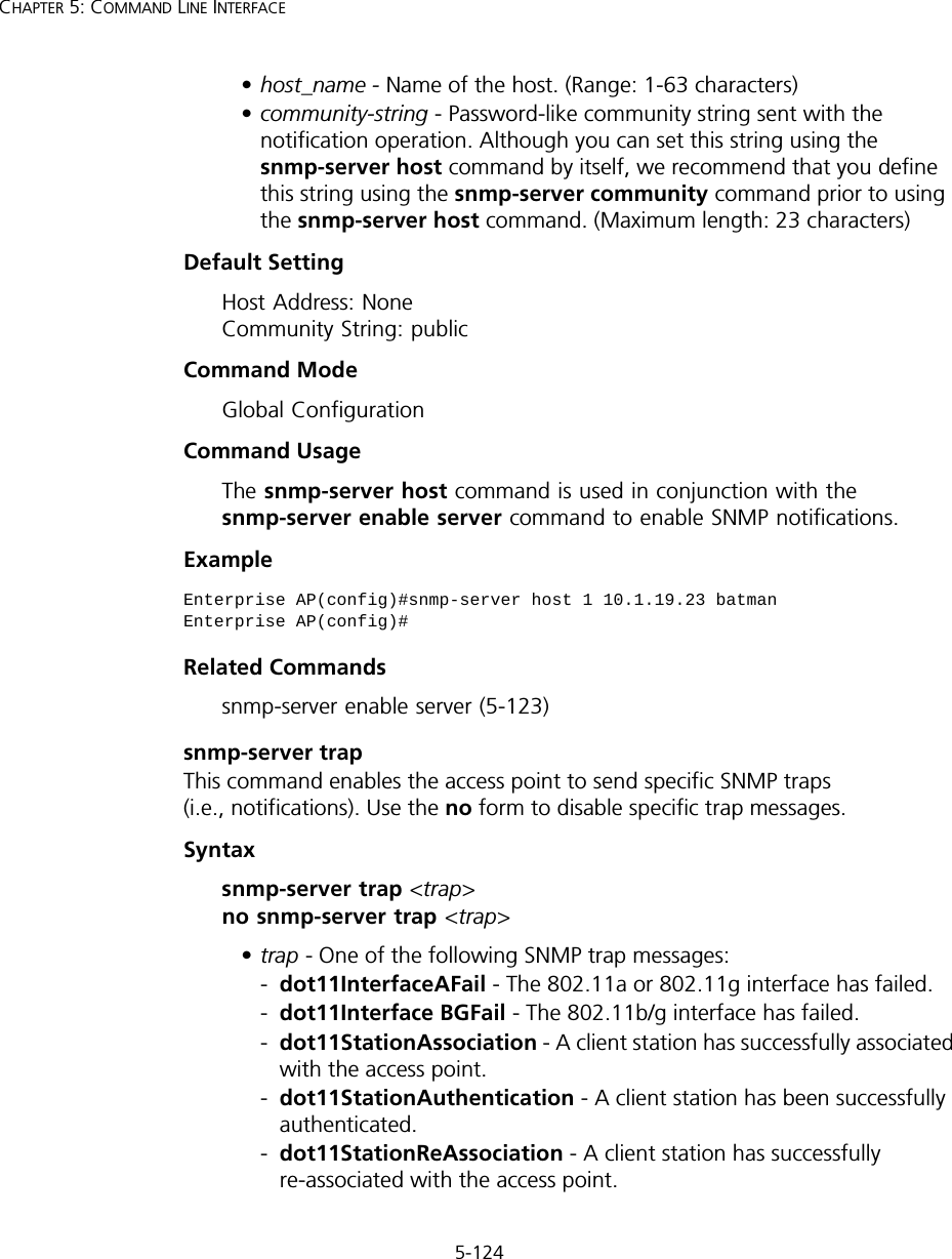
5-124CHAPTER 5: COMMAND LINE INTERFACE•host_name - Name of the host. (Range: 1-63 characters)•community-string - Password-like community string sent with the notification operation. Although you can set this string using the snmp-server host command by itself, we recommend that you define this string using the snmp-server community command prior to using the snmp-server host command. (Maximum length: 23 characters)Default Setting Host Address: None Community String: publicCommand Mode Global ConfigurationCommand Usage The snmp-server host command is used in conjunction with the snmp-server enable server command to enable SNMP notifications. Example Related Commandssnmp-server enable server (5-123)snmp-server trapThis command enables the access point to send specific SNMP traps (i.e., notifications). Use the no form to disable specific trap messages.Syntaxsnmp-server trap <trap> no snmp-server trap <trap>•trap - One of the following SNMP trap messages:-dot11InterfaceAFail - The 802.11a or 802.11g interface has failed.-dot11Interface BGFail - The 802.11b/g interface has failed.-dot11StationAssociation - A client station has successfully associated with the access point.-dot11StationAuthentication - A client station has been successfully authenticated.-dot11StationReAssociation - A client station has successfully re-associated with the access point.Enterprise AP(config)#snmp-server host 1 10.1.19.23 batmanEnterprise AP(config)#
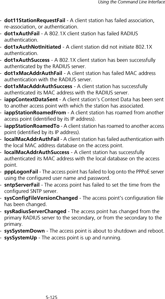
5-125Using the Command Line Interface-dot11StationRequestFail - A client station has failed association, re-association, or authentication.-dot1xAuthFail - A 802.1X client station has failed RADIUS authentication.-dot1xAuthNotInitiated - A client station did not initiate 802.1X authentication.-dot1xAuthSuccess - A 802.1X client station has been successfully authenticated by the RADIUS server.-dot1xMacAddrAuthFail - A client station has failed MAC address authentication with the RADIUS server.-dot1xMacAddrAuthSuccess - A client station has successfully authenticated its MAC address with the RADIUS server.-iappContextDataSent - A client station’s Context Data has been sent to another access point with which the station has associated.-iappStationRoamedFrom - A client station has roamed from another access point (identified by its IP address).-iappStationRoamedTo - A client station has roamed to another access point (identified by its IP address).-localMacAddrAuthFail - A client station has failed authentication with the local MAC address database on the access point.-localMacAddrAuthSuccess - A client station has successfully authenticated its MAC address with the local database on the access point.-pppLogonFail - The access point has failed to log onto the PPPoE server using the configured user name and password.-sntpServerFail - The access point has failed to set the time from the configured SNTP server.-sysConfigFileVersionChanged - The access point’s configuration file has been changed.-sysRadiusServerChanged - The access point has changed from the primary RADIUS server to the secondary, or from the secondary to the primary.-sysSystemDown - The access point is about to shutdown and reboot.-sysSystemUp - The access point is up and running.
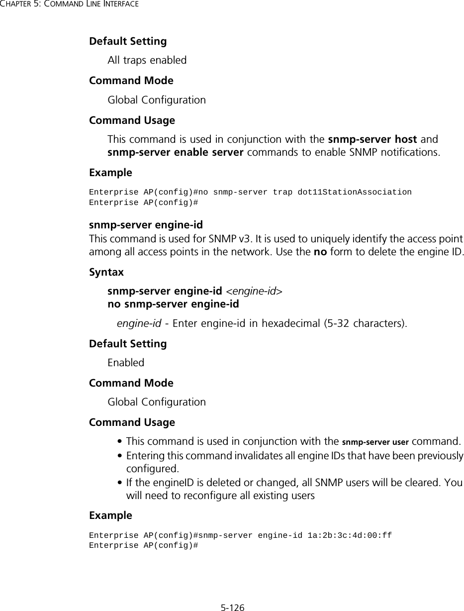
5-126CHAPTER 5: COMMAND LINE INTERFACEDefault Setting All traps enabledCommand Mode Global ConfigurationCommand Usage This command is used in conjunction with the snmp-server host and snmp-server enable server commands to enable SNMP notifications.Example snmp-server engine-idThis command is used for SNMP v3. It is used to uniquely identify the access point among all access points in the network. Use the no form to delete the engine ID.Syntax snmp-server engine-id <engine-id>  no snmp-server engine-id engine-id - Enter engine-id in hexadecimal (5-32 characters). Default Setting EnabledCommand Mode Global ConfigurationCommand Usage • This command is used in conjunction with the snmp-server user command. • Entering this command invalidates all engine IDs that have been previously configured. • If the engineID is deleted or changed, all SNMP users will be cleared. You will need to reconfigure all existing usersExample Enterprise AP(config)#no snmp-server trap dot11StationAssociationEnterprise AP(config)#Enterprise AP(config)#snmp-server engine-id 1a:2b:3c:4d:00:ffEnterprise AP(config)#
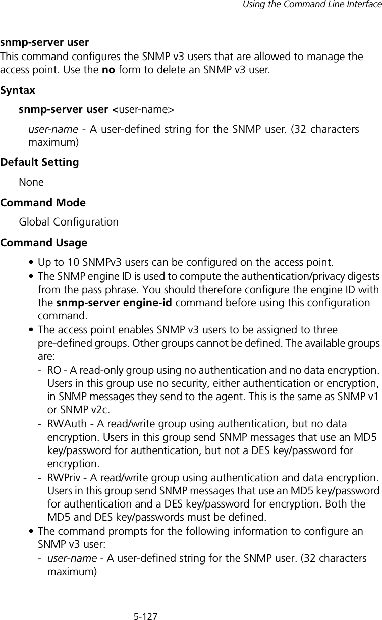
5-127Using the Command Line Interfacesnmp-server userThis command configures the SNMP v3 users that are allowed to manage the access point. Use the no form to delete an SNMP v3 user.Syntaxsnmp-server user <user-name>user-name - A user-defined string for the SNMP user. (32 characters maximum)Default Setting NoneCommand Mode Global ConfigurationCommand Usage • Up to 10 SNMPv3 users can be configured on the access point.• The SNMP engine ID is used to compute the authentication/privacy digests from the pass phrase. You should therefore configure the engine ID with the snmp-server engine-id command before using this configuration command.• The access point enables SNMP v3 users to be assigned to three pre-defined groups. Other groups cannot be defined. The available groups are:- RO - A read-only group using no authentication and no data encryption. Users in this group use no security, either authentication or encryption, in SNMP messages they send to the agent. This is the same as SNMP v1 or SNMP v2c.- RWAuth - A read/write group using authentication, but no data encryption. Users in this group send SNMP messages that use an MD5 key/password for authentication, but not a DES key/password for encryption.- RWPriv - A read/write group using authentication and data encryption. Users in this group send SNMP messages that use an MD5 key/password for authentication and a DES key/password for encryption. Both the MD5 and DES key/passwords must be defined.• The command prompts for the following information to configure an SNMP v3 user:-user-name - A user-defined string for the SNMP user. (32 characters maximum)
5-128CHAPTER 5: COMMAND LINE INTERFACE-group-name - The name of the SNMP group to which the user is assigned (32 characters maximum). There are three pre-defined groups: RO, RWAuth, or RWPriv.-auth-proto - The authentication type used for user authentication: md5 or none.-auth-passphrase - The user password required when authentication is used (8 – 32 characters).-priv-proto - The encryption type used for SNMP data encryption: des or none.-priv-passphrase - The user password required when data encryption is used (8 – 32 characters).• Users must be assigned to groups that have the same security levels. If a user who has “AuthPriv” security (uses authentication and encryption) is assigned to a read-only (RO) group, the user will not be able to access the database. An AuthPriv user must be assigned to the RWPriv group with the AuthPriv security level.• To configure a user for the RWAuth group, you must include the auth-proto and auth-passphrase keywords.• To configure a user for the RWPriv group, you must include the auth-proto, auth-passphrase, priv-proto, and priv-passphrase keywords.Example snmp-server targetsThis command configures SNMP v3 notification targets. Use the no form to delete an SNMP v3 target.Syntaxsnmp-server targets <target-id> <ip-addr> <sec-name>    [version {3}] [udp-port {port-number}] [notification-type    {TRAP}] no snmp-server targets <target-id>•target-id - A user-defined name that identifies a receiver of SNMP notifications. (Maximum length: 32 characters)Enterprise AP(config)#snmp-server user User Name<1-32> :chrisGroup Name<1-32> :RWPrivAuthtype(md5,<cr>none):md5Passphrase<8-32>:a good secretPrivacy(des,<cr>none) :desPassphrase<8-32>:a very good secretEnterprise AP(config)#
5-129Using the Command Line Interface•ip-addr - Specifies the IP address of the management station to receive notifications.•sec-name -  The defined SNMP v3 user name that is to receive notifications.•version - The SNMP version of notifications. Currently only version 3 is supported in this command.•udp-port - The UDP port that is used on the receiving management station for notifications.•notification-type - The type of notification that is sent. Currently only TRAP is supported.Default Setting NoneCommand Mode Global ConfigurationCommand Usage • The access point supports up to 10 SNMP v3 target IDs.• The SNMP v3 user name that is specified in the target must first be configured using the snmp-server user command.Example snmp-server filterThis command configures SNMP v3 notification filters. Use the no form to delete an SNMP v3 filter or remove a subtree from a filter.Syntaxsnmp-server filter <filter-id> <include | exclude> <subtree>    [mask {mask}] no snmp-server filter <filter-id> [subtree]•filter-id - A user-defined name that identifies an SNMP v3 notification filter. (Maximum length: 32 characters)•include - Defines a filter type that includes objects in the MIB subtree.•exclude - Defines a filter type that excludes objects in the MIB subtree.•subtree - The part of the MIB subtree that is to be filtered.•mask - An optional hexadecimal value bit mask to define objects in the MIB subtree. Enterprise AP(config)#snmp-server targets mytraps 192.254.2.33 chrisEnterprise AP(config)#
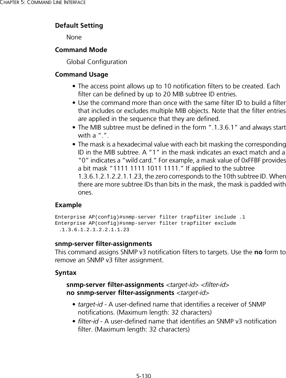
5-130CHAPTER 5: COMMAND LINE INTERFACEDefault Setting NoneCommand Mode Global ConfigurationCommand Usage • The access point allows up to 10 notification filters to be created. Each filter can be defined by up to 20 MIB subtree ID entries.• Use the command more than once with the same filter ID to build a filter that includes or excludes multiple MIB objects. Note that the filter entries are applied in the sequence that they are defined.• The MIB subtree must be defined in the form “.1.3.6.1” and always start with a “.”.• The mask is a hexadecimal value with each bit masking the corresponding ID in the MIB subtree. A “1” in the mask indicates an exact match and a “0” indicates a “wild card.” For example, a mask value of 0xFFBF provides a bit mask “1111 1111 1011 1111.” If applied to the subtree 1.3.6.1.2.1.2.2.1.1.23, the zero corresponds to the 10th subtree ID. When there are more subtree IDs than bits in the mask, the mask is padded with ones.Example snmp-server filter-assignmentsThis command assigns SNMP v3 notification filters to targets. Use the no form to remove an SNMP v3 filter assignment.Syntaxsnmp-server filter-assignments <target-id> <filter-id>  no snmp-server filter-assignments <target-id> •target-id - A user-defined name that identifies a receiver of SNMP notifications. (Maximum length: 32 characters)•filter-id - A user-defined name that identifies an SNMP v3 notification filter. (Maximum length: 32 characters)Enterprise AP(config)#snmp-server filter trapfilter include .1Enterprise AP(config)#snmp-server filter trapfilter exclude .1.3.6.1.2.1.2.2.1.1.23
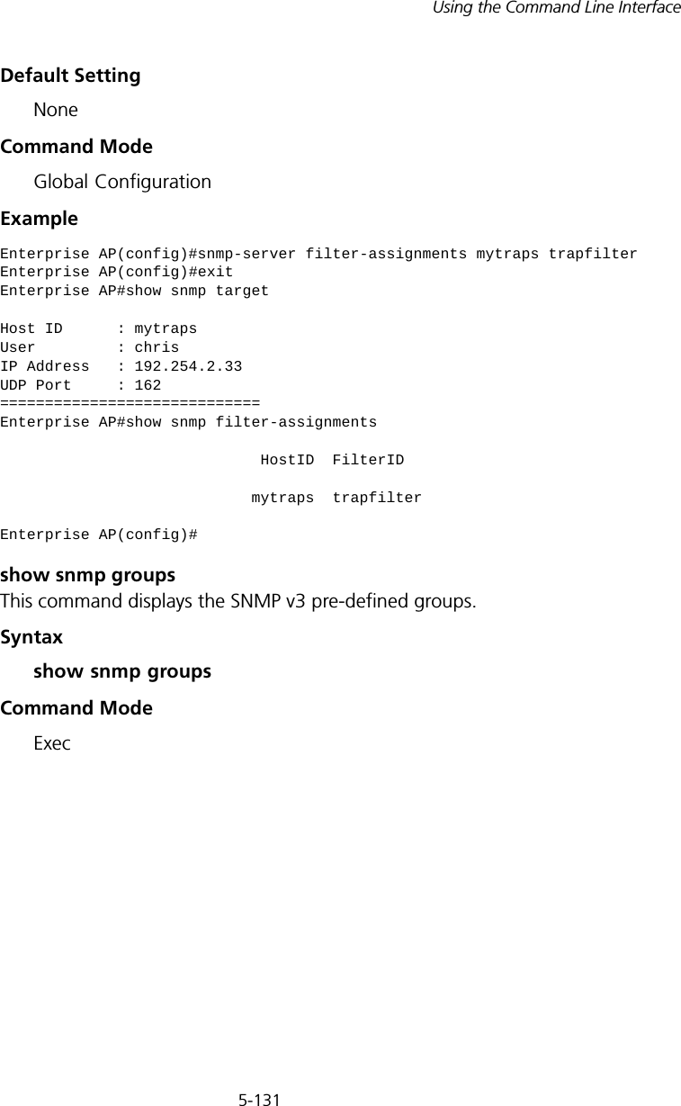
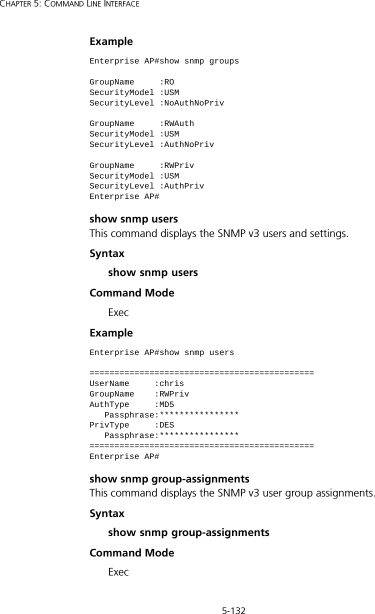
5-131Using the Command Line InterfaceDefault Setting NoneCommand Mode Global ConfigurationExample show snmp groupsThis command displays the SNMP v3 pre-defined groups.Syntax show snmp groupsCommand ModeExecEnterprise AP(config)#snmp-server filter-assignments mytraps trapfilterEnterprise AP(config)#exitEnterprise AP#show snmp targetHost ID      : mytrapsUser         : chrisIP Address   : 192.254.2.33UDP Port     : 162=============================Enterprise AP#show snmp filter-assignments                             HostID  FilterID                            mytraps  trapfilterEnterprise AP(config)#
5-132CHAPTER 5: COMMAND LINE INTERFACEExample show snmp usersThis command displays the SNMP v3 users and settings.Syntax show snmp usersCommand ModeExecExample show snmp group-assignmentsThis command displays the SNMP v3 user group assignments.Syntax show snmp group-assignmentsCommand ModeExecEnterprise AP#show snmp groupsGroupName     :ROSecurityModel :USMSecurityLevel :NoAuthNoPrivGroupName     :RWAuthSecurityModel :USMSecurityLevel :AuthNoPrivGroupName     :RWPrivSecurityModel :USMSecurityLevel :AuthPrivEnterprise AP#Enterprise AP#show snmp users=============================================UserName     :chrisGroupName    :RWPrivAuthType     :MD5   Passphrase:****************PrivType     :DES   Passphrase:****************=============================================Enterprise AP#
5-133Using the Command Line InterfaceExample show snmp targetThis command displays the SNMP v3 notification target settings.Syntaxshow snmp targetCommand Mode ExecExample show snmp filterThis command displays the SNMP v3 notification filter settings.Syntaxshow snmp filter [filter-id] •filter-id - A user-defined name that identifies an SNMP v3 notification filter. (Maximum length: 32 characters)Command Mode ExecEnterprise AP#show snmp group-assignmentsGroupName    :RWPrivUserName     :chrisEnterprise AP#Enterprise AP#Enterprise AP#show snmp targetHost ID      : mytrapsUser         : chrisIP Address   : 192.254.2.33UDP Port     : 162=============================Enterprise AP#
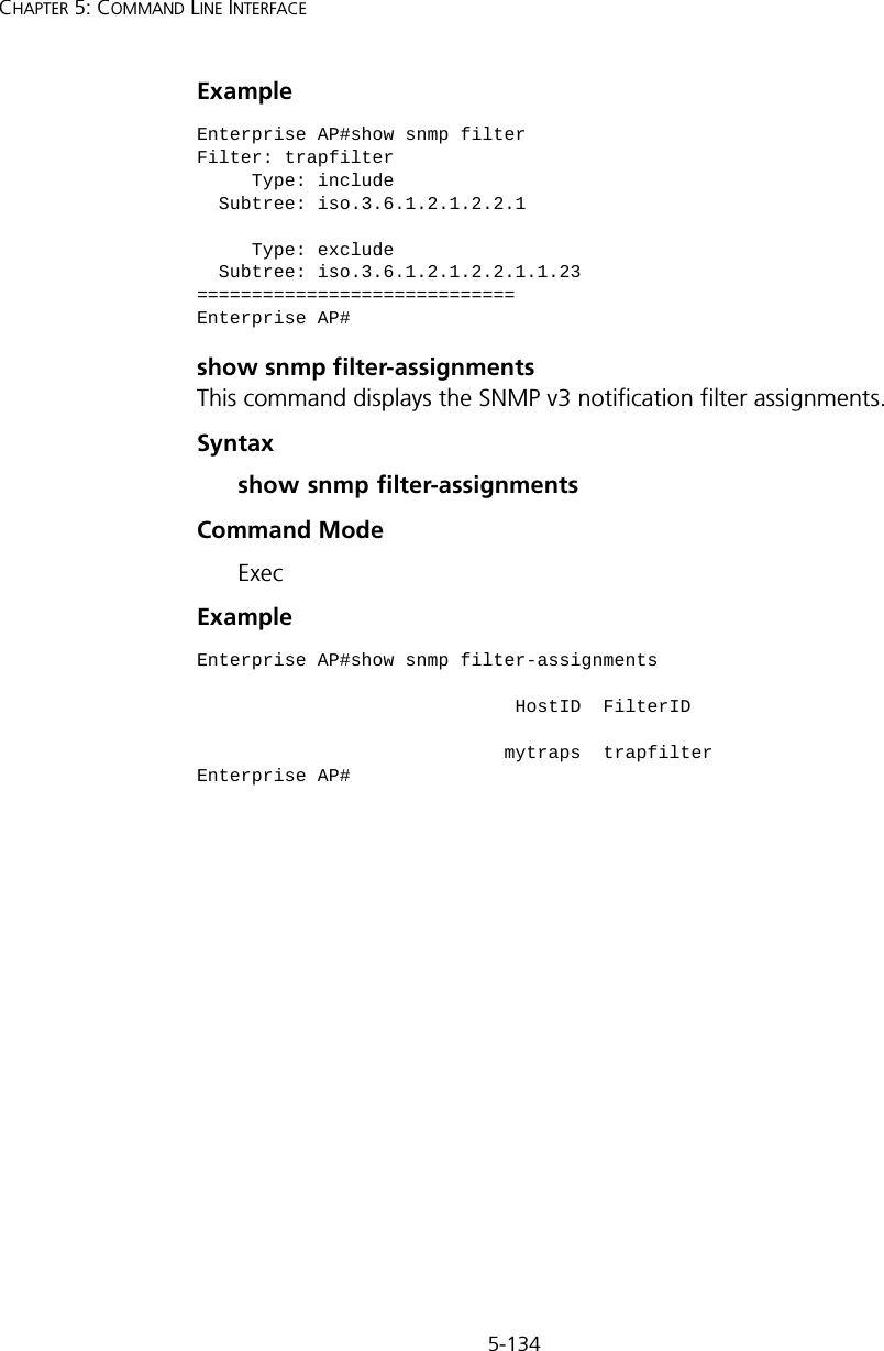
5-134CHAPTER 5: COMMAND LINE INTERFACEExample show snmp filter-assignmentsThis command displays the SNMP v3 notification filter assignments.Syntaxshow snmp filter-assignmentsCommand Mode ExecExample Enterprise AP#show snmp filterFilter: trapfilter     Type: include  Subtree: iso.3.6.1.2.1.2.2.1     Type: exclude  Subtree: iso.3.6.1.2.1.2.2.1.1.23=============================Enterprise AP#Enterprise AP#show snmp filter-assignments                             HostID  FilterID                            mytraps  trapfilterEnterprise AP#
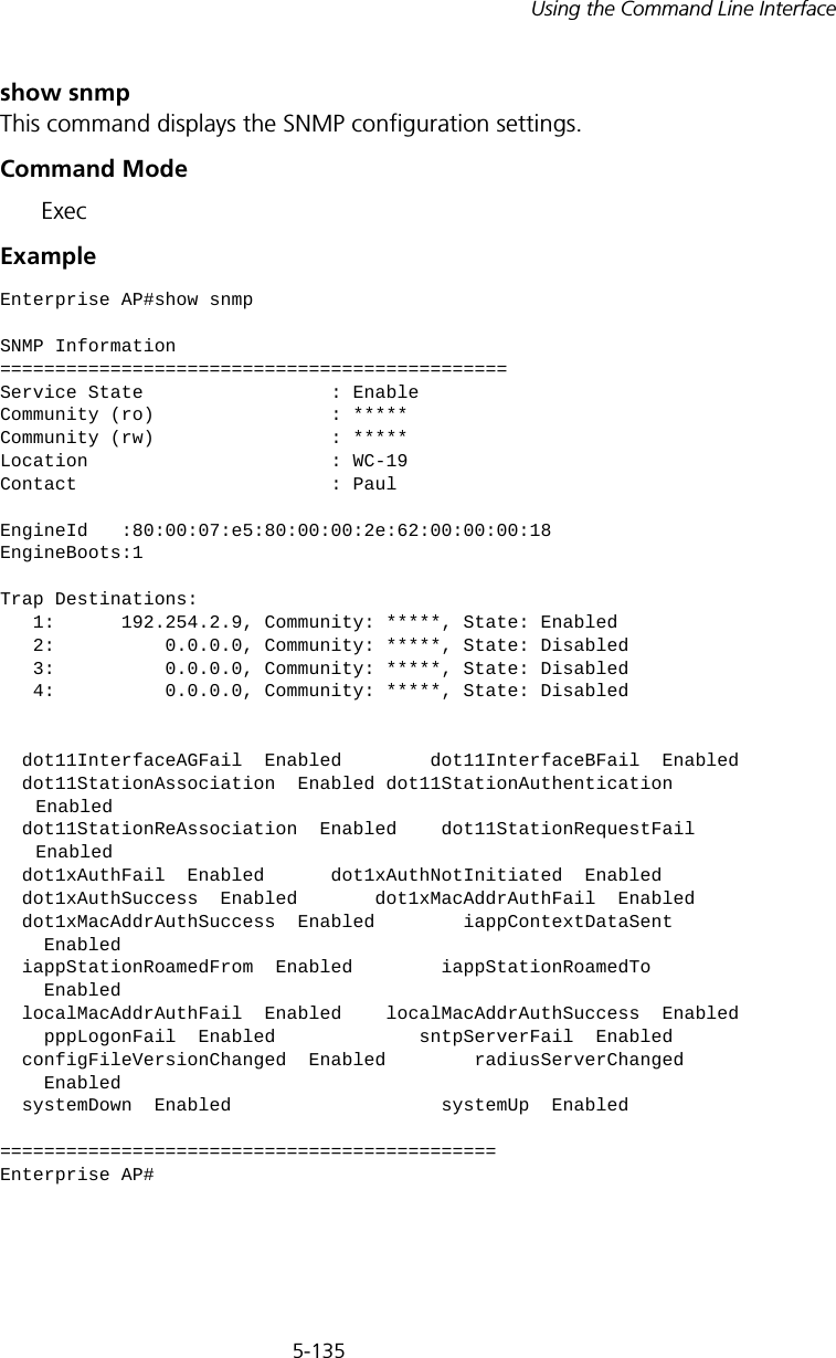
5-135Using the Command Line Interfaceshow snmpThis command displays the SNMP configuration settings.Command Mode ExecExampleEnterprise AP#show snmpSNMP Information==============================================Service State                 : EnableCommunity (ro)                : *****Community (rw)                : *****Location                      : WC-19Contact                       : PaulEngineId   :80:00:07:e5:80:00:00:2e:62:00:00:00:18EngineBoots:1Trap Destinations:   1:      192.254.2.9, Community: *****, State: Enabled   2:          0.0.0.0, Community: *****, State: Disabled   3:          0.0.0.0, Community: *****, State: Disabled   4:          0.0.0.0, Community: *****, State: Disabled  dot11InterfaceAGFail  Enabled        dot11InterfaceBFail  Enabled      dot11StationAssociation  Enabled dot11StationAuthentication     Enabled  dot11StationReAssociation  Enabled    dot11StationRequestFail     Enabled  dot1xAuthFail  Enabled      dot1xAuthNotInitiated  Enabled  dot1xAuthSuccess  Enabled       dot1xMacAddrAuthFail  Enabled  dot1xMacAddrAuthSuccess  Enabled        iappContextDataSent      Enabled  iappStationRoamedFrom  Enabled        iappStationRoamedTo      Enabled  localMacAddrAuthFail  Enabled    localMacAddrAuthSuccess  Enabled    pppLogonFail  Enabled             sntpServerFail  Enabled  configFileVersionChanged  Enabled        radiusServerChanged      Enabled  systemDown  Enabled                   systemUp  Enabled=============================================Enterprise AP#
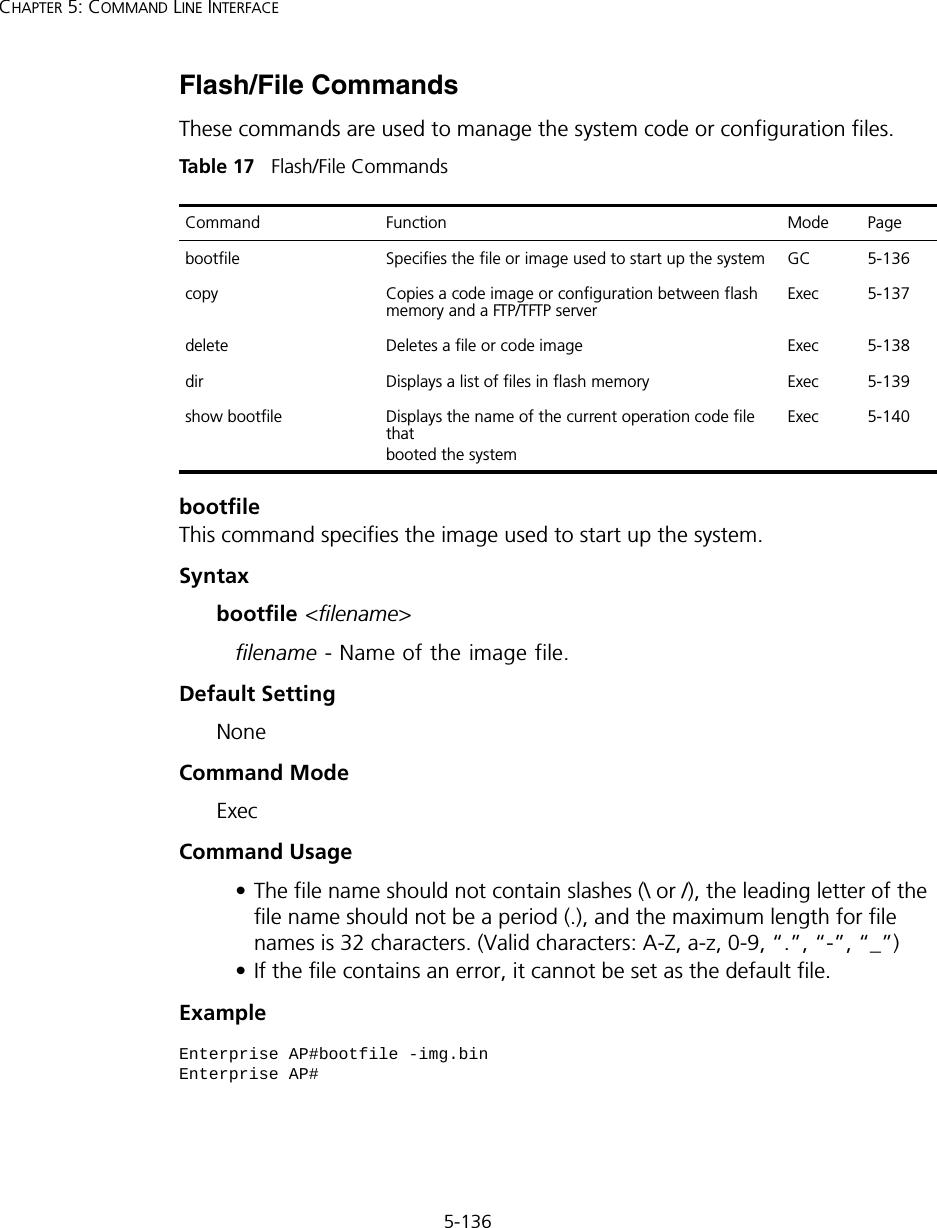
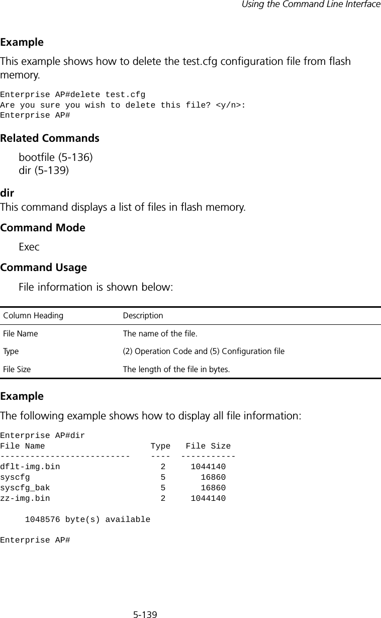
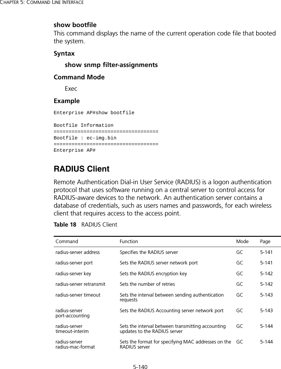
5-136CHAPTER 5: COMMAND LINE INTERFACEFlash/File CommandsThese commands are used to manage the system code or configuration files.Tabl e  17   Flash/File CommandsbootfileThis command specifies the image used to start up the system.Syntaxbootfile <filename>filename - Name of the image file.Default Setting NoneCommand Mode ExecCommand Usage • The file name should not contain slashes (\ or /), the leading letter of the file name should not be a period (.), and the maximum length for file names is 32 characters. (Valid characters: A-Z, a-z, 0-9, “.”, “-”, “_”)• If the file contains an error, it cannot be set as the default file. ExampleCommand Function Mode Pagebootfile Specifies the file or image used to start up the system  GC 5-136copy  Copies a code image or configuration between flash memory and a FTP/TFTP serverExec 5-137delete  Deletes a file or code image  Exec 5-138dir  Displays a list of files in flash memory  Exec 5-139show bootfile Displays the name of the current operation code file thatbooted the systemExec 5-140Enterprise AP#bootfile -img.binEnterprise AP#
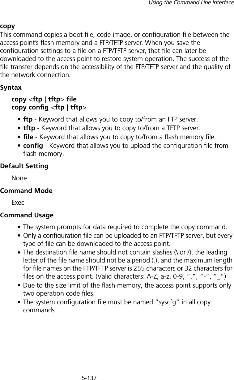
5-137Using the Command Line Interfacecopy This command copies a boot file, code image, or configuration file between the access point’s flash memory and a FTP/TFTP server. When you save the configuration settings to a file on a FTP/TFTP server, that file can later be downloaded to the access point to restore system operation. The success of the file transfer depends on the accessibility of the FTP/TFTP server and the quality of the network connection. Syntaxcopy <ftp | tftp> file copy config <ftp | tftp>•ftp - Keyword that allows you to copy to/from an FTP server.•tftp - Keyword that allows you to copy to/from a TFTP server.•file - Keyword that allows you to copy to/from a flash memory file. •config - Keyword that allows you to upload the configuration file from flash memory. Default Setting NoneCommand Mode ExecCommand Usage • The system prompts for data required to complete the copy command. • Only a configuration file can be uploaded to an FTP/TFTP server, but every type of file can be downloaded to the access point.•The destination file name should not contain slashes (\ or /), the leading letter of the file name should not be a period (.), and the maximum length for file names on the FTP/TFTP server is 255 characters or 32 characters for files on the access point. (Valid characters: A-Z, a-z, 0-9, “.”, “-”, “_”)• Due to the size limit of the flash memory, the access point supports only two operation code files.• The system configuration file must be named “syscfg” in all copy commands.
5-138CHAPTER 5: COMMAND LINE INTERFACEExample The following example shows how to upload the configuration settings to a file on the TFTP server:The following example shows how to download a configuration file: deleteThis command deletes a file or image.Syntaxdelete <filename>filename - Name of the configuration file or image name.Default Setting NoneCommand Mode ExecEnterprise AP#copy config tftpTFTP Source file name:syscfgTFTP Server IP:192.254.2.19Enterprise AP#Enterprise AP#copy tftp file1. Application image2. Config file3. Boot block imageSelect the type of download<1,2,3>:  [1]:2TFTP Source file name:syscfgTFTP Server IP:192.254.2.19Enterprise AP#NOTE: Beware of deleting application images from flash memory. At least one application image is required in order to boot the access point. If there are multiple image files in flash memory, and the one used to boot the access point is deleted, be sure you first use the bootfile command to update the application image file booted at startup before you reboot the access point.
5-139Using the Command Line InterfaceExample This example shows how to delete the test.cfg configuration file from flash memory.Related Commandsbootfile (5-136) dir (5-139)dirThis command displays a list of files in flash memory.Command Mode ExecCommand Usage File information is shown below:Example The following example shows how to display all file information:Enterprise AP#delete test.cfgAre you sure you wish to delete this file? <y/n>:Enterprise AP#Column Heading DescriptionFile Name The name of the file.Type (2) Operation Code and (5) Configuration fileFile Size The length of the file in bytes.Enterprise AP#dirFile Name                     Type   File Size--------------------------    ----  -----------dflt-img.bin                    2     1044140syscfg                          5       16860syscfg_bak                      5       16860zz-img.bin                      2     1044140     1048576 byte(s) availableEnterprise AP#
5-140CHAPTER 5: COMMAND LINE INTERFACEshow bootfileThis command displays the name of the current operation code file that booted the system.Syntaxshow snmp filter-assignmentsCommand Mode ExecExample RADIUS ClientRemote Authentication Dial-in User Service (RADIUS) is a logon authentication protocol that uses software running on a central server to control access for RADIUS-aware devices to the network. An authentication server contains a database of credentials, such as users names and passwords, for each wireless client that requires access to the access point.Tabl e  18   RADIUS ClientEnterprise AP#show bootfileBootfile Information===================================Bootfile : ec-img.bin===================================Enterprise AP#Command Function Mode Pageradius-server address Specifies the RADIUS server  GC 5-141radius-server port  Sets the RADIUS server network port  GC 5-141radius-server key  Sets the RADIUS encryption key  GC 5-142radius-server retransmit  Sets the number of retries  GC 5-142radius-server timeout  Sets the interval between sending authentication requestsGC 5-143radius-server port-accounting Sets the RADIUS Accounting server network port GC 5-143radius-server timeout-interimSets the interval between transmitting accounting updates to the RADIUS serverGC 5-144radius-server radius-mac-format Sets the format for specifying MAC addresses on the RADIUS server GC 5-144
5-141Using the Command Line Interfaceradius-server addressThis command specifies the primary and secondary RADIUS servers. Syntaxradius-server [secondary] address <host_ip_address | host_name>•secondary - Secondary server.•host_ip_address - IP address of server.•host_name - Host name of server. (Range: 1-20 characters)Default Setting NoneCommand Mode Global ConfigurationExample radius-server portThis command sets the RADIUS server network port. Syntaxradius-server [secondary] port <port_number>•secondary - Secondary server.•port_number - RADIUS server UDP port used for authentication messages. (Range: 1024-65535)Default Setting 1812Command Mode Global Configurationradius-server vlan-format Sets the format for specifying VLAN IDs on the RADIUS serverGC 5-145show radius Shows the current RADIUS settings Exec 5-145Enterprise AP(config)#radius-server address 192.254.2.25Enterprise AP(config)#Command Function Mode Page
5-142CHAPTER 5: COMMAND LINE INTERFACEExample radius-server keyThis command sets the RADIUS encryption key. Syntax radius-server [secondary] key <key_string>•secondary - Secondary server.•key_string - Encryption key used to authenticate logon access for client. Do not use blank spaces in the string. (Maximum length: 20 characters)Default Setting DEFAULTCommand Mode Global ConfigurationExample radius-server retransmitThis command sets the number of retries. Syntaxradius-server [secondary] retransmit number_of_retries•secondary - Secondary server.•number_of_retries - Number of times the access point will try to authenticate logon access via the RADIUS server. (Range: 1 - 30)Default Setting 3Command Mode Global ConfigurationExample Enterprise AP(config)#radius-server port 181Enterprise AP(config)#Enterprise AP(config)#radius-server key greenEnterprise AP(config)#Enterprise AP(config)#radius-server retransmit 5Enterprise AP(config)#
5-143Using the Command Line Interfaceradius-server timeoutThis command sets the interval between transmitting authentication requests to the RADIUS server. Syntax radius-server [secondary] timeout number_of_seconds•secondary - Secondary server.•number_of_seconds - Number of seconds the access point waits for a reply before resending a request. (Range: 1-60)Default Setting 5Command Mode Global ConfigurationExample radius-server port-accountingThis command sets the RADIUS Accounting server network port. Syntaxradius-server [secondary] port-accounting <port_number>•secondary - Secondary server. If secondary is not specified, then the access point assumes you are configuring the primary RADIUS server.•port_number - RADIUS Accounting server UDP port used for accounting messages.  (Range: 0 or 1024-65535)Default Setting 0 (disabled)Command Mode Global ConfigurationCommand Usage • When the RADIUS Accounting server UDP port is specified, a RADIUS accounting session is automatically started for each user that is successfully authenticated to the access point.Enterprise AP(config)#radius-server timeout 10Enterprise AP(config)#
5-144CHAPTER 5: COMMAND LINE INTERFACEExample radius-server timeout-interimThis command sets the interval between transmitting accounting updates to the RADIUS server.Syntax radius-server [secondary] timeout-interim <number_of_seconds>•secondary - Secondary server.•number_of_seconds - Number of seconds the access point waits between transmitting accounting updates. (Range: 60-86400)Default Setting 3600Command Mode Global ConfigurationCommand Usage • The access point sends periodic accounting updates after every interim period until the user logs off and a “stop” message is sent.Example radius-server radius-mac-formatThis command sets the format for specifying MAC addresses on the RADIUS server.Syntaxradius-server radius-mac-format <multi-colon | multi-dash | no-delimiter | single-dash>•multi-colon - Enter MAC addresses in the form xx:xx:xx:xx:xx:xx.•multi-dash - Enter MAC addresses in the form xx-xx-xx-xx-xx-xx.•no-delimiter - Enter MAC addresses in the form xxxxxxxxxxxx.•single-dash - Enter MAC addresses in the form xxxxxx-xxxxxx.Enterprise AP(config)#radius-server port-accounting 1813Enterprise AP(config)#Enterprise AP(config)#radius-server timeout-interim 500Enterprise AP(config)#
5-145Using the Command Line InterfaceDefault SettingNo delimiterCommand ModeGlobal ConfigurationExample radius-server vlan-formatThis command sets the format for specifying VLAN IDs on the RADIUS server.Syntaxradius-server vlan-format <hex | ascii>•hex - Enter VLAN IDs as a hexadecimal number.•ascii - Enter VLAN IDs as an ASCII string.Default SettingHexCommand ModeGlobal ConfigurationExample show radiusThis command displays the current settings for the RADIUS server.Default SettingNoneCommand Mode ExecEnterprise AP(config)#radius-server radius-mac-format multi-dashEnterprise AP(config)#Enterprise AP(config)#radius-server vlan-format asciiEnterprise AP(config)#
5-146CHAPTER 5: COMMAND LINE INTERFACEExample 802.1X AuthenticationThe access point supports IEEE 802.1X access control for wireless clients. This control feature prevents unauthorized access to the network by requiring an 802.1X client application to submit user credentials for authentication. Client authentication is then verified by a RADIUS server using EAP (Extensible Authentication Protocol) before the access point grants client access to the network. The 802.1X EAP packets are also used to pass dynamic unicast session keys and static broadcast keys to wireless clients.Tabl e  19   802.1X AuthenticationEnterprise AP#show radiusRadius Server Information========================================IP                 : 0.0.0.0Port               : 1812Key                : *****Retransmit         : 3Timeout            : 5Radius MAC format  : no-delimiterRadius VLAN format : HEX========================================Radius Secondary Server Information========================================IP                 : 0.0.0.0Port               : 1812Key                : *****Retransmit         : 3Timeout            : 5Radius MAC format  : no-delimiterRadius VLAN format : HEX========================================Enterprise AP#Command Function Mode Page802.1x Configures 802.1X as disabled, supported, or required IC-W-VAP 5-147802.1x broadcast-key- refresh-rateSets the interval at which the primary broadcast keys are refreshed for stations using 802.1X dynamic keyingIC-W-VAP 5-148802.1x session-key- refresh-rate Sets the interval at which unicast session keys are refreshed for associated stations using dynamic keyingIC-W-VAP 5-149802.1x session-timeout Sets the timeout after which a connected client must be re-authenticated IC-W-VAP 5-149
5-147Using the Command Line Interface802.1xThis command configures 802.1X as optionally supported or as required for wireless clients. Use the no form to disable 802.1X support.Syntax802.1x <supported | required> no 802.1x•supported - Authenticates clients that initiate the 802.1X authentication process. Uses standard 802.11 authentication for all others.•required - Requires 802.1X authentication for all clients.Default SettingDisabledCommand ModeGlobal ConfigurationCommand Usage• When 802.1X is disabled, the access point does not support 802.1X authentication for any station. After successful 802.11 association, each client is allowed to access the network.• When 802.1X is supported, the access point supports 802.1X authentication only for clients initiating the 802.1X authentication process (i.e., the access point does NOT initiate 802.1X authentication). For stations initiating 802.1X, only those stations successfully authenticated are allowed to access the network. For those stations not initiating 802.1X, access to the network is allowed after successful 802.11 association.802.1x-supplicant enable Enables the access point to operate as a 802.1X supplicantGC 5-150802.1x-supplicant user Sets the supplicant user name and password for the access pointGC 5-150show authentication Shows all 802.1X authentication settings, as well as the address filter table Exec 5-150Command Function Mode Page
5-148CHAPTER 5: COMMAND LINE INTERFACE• When 802.1X is required, the access point enforces 802.1X authentication for all 802.11 associated stations. If 802.1X authentication is not initiated by the station, the access point will initiate authentication. Only those stations successfully authenticated with 802.1X are allowed to access the network.• 802.1X does not apply to the 10/100Base-TX port.Example802.1x broadcast-key-refresh-rateThis command sets the interval at which the broadcast keys are refreshed for stations using 802.1X dynamic keying. Syntax802.1x broadcast-key-refresh-rate <rate>rate - The interval at which the access point rotates broadcast keys. (Range: 0 - 1440 minutes)Default Setting0 (Disabled)Command ModeGlobal ConfigurationCommand Usage• The access point uses Enterprise APOL (Extensible Authentication Protocol Over LANs) packets to pass dynamic unicast session and broadcast keys to wireless clients. The 802.1x broadcast-key-refresh-rate command specifies the interval after which the broadcast keys are changed. The 802.1x session-key-refresh-rate command specifies the interval after which unicast session keys are changed.• Dynamic broadcast key rotation allows the access point to generate a random group key and periodically update all key-management capable wireless clients.ExampleEnterprise AP(config)#802.1x supportedEnterprise AP(config)#Enterprise AP(config)#802.1X broadcast-key-refresh-rate 5Enterprise AP(config)#
5-149Using the Command Line Interface802.1x session-key-refresh-rateThis command sets the interval at which unicast session keys are refreshed for associated stations using dynamic keying.Syntax802.1x session-key-refresh-rate <rate>rate - The interval at which the access point refreshes a session key. (Range: 0 - 1440 minutes)Default Setting0 (Disabled)Command ModeGlobal ConfigurationCommand UsageSession keys are unique to each client, and are used to authenticate a client connection, and correlate traffic passing between a specific client and the access point.Example802.1x session-timeoutThis command sets the time period after which a connected client must be re-authenticated. Use the no form to disable 802.1X re-authentication.Syntax802.1x session-timeout <seconds> no 802.1x session-timeoutseconds - The number of seconds. (Range: 0-65535)Default0 (Disabled)Command ModeGlobal ConfigurationEnterprise AP(config)#802.1x session-key-refresh-rate 5Enterprise AP(config)#
5-150CHAPTER 5: COMMAND LINE INTERFACEExample802.1x-supplicant enableThis command enables the access point to operate as an 802.1X supplicant for authentication. Use the no form to disable 802.1X authentication of the access point.Syntax802.1x-supplicant enable no 802.1x-supplicantDefaultDisabledCommand ModeGlobal ConfigurationCommand UsageA user name and password must be configured first before the 802.1X supplicant feature can be enabled.Example802.1x-supplicant userThis command sets the user name and password used for authentication of the access point when operating as a 802.1X supplicant. Use the no form to clear the supplicant user name and password.Syntax802.1x-supplicant user <username> <password> no 802.1x-supplicant user•username - The access point name used for authentication to the network. (Range: 1-32 alphanumeric characters)•password - The MD5 password used for access point authentication. (Range: 1-32 alphanumeric characters)Enterprise AP(config)#802.1x session-timeout 300Enterprise AP(config)#Enterprise AP(config)#802.1x-supplicant enableEnterprise AP(config)#
5-151Using the Command Line InterfaceDefaultNoneCommand ModeGlobal ConfigurationCommand UsageThe access point currently only supports EAP-MD5 CHAP for 802.1X supplicant authentication.Exampleshow authenticationThis command shows all 802.1X authentication settings, as well as the address filter table.Command ModeExecExampleEnterprise AP(config)#802.1x-supplicant user AP8760 dot1xpassEnterprise AP(config)#Enterprise AP#show authenticationAuthentication Information===========================================================MAC Authentication Server      : DISABLEDMAC Auth Session Timeout Value : 0 min802.1x supplicant              : DISABLED802.1x supplicant user         : EMPTY802.1x supplicant password     : EMPTYAddress Filtering              : ALLOWEDSystem Default : ALLOW addresses not found in filter table.Filter TableMAC Address             Status-----------------       ----------00-70-50-cc-99-1a       DENIED00-70-50-cc-99-1b       ALLOWED=========================================================Enterprise AP(config)#
5-152CHAPTER 5: COMMAND LINE INTERFACEMAC Address Authentication Use these commands to define MAC authentication on the access point. For local MAC authentication, first define the default filtering policy using the address filter default command. Then enter the MAC addresses to be filtered, indicating if they are allowed or denied. For RADIUS MAC authentication, the MAC addresses and filtering policy must be configured on the RADIUS server.Tabl e  20   MAC Address Authenticationaddress filter defaultThis command sets filtering to allow or deny listed MAC addresses.Syntaxaddress filter default <allowed | denied>•allowed - Only MAC addresses entered as “denied” in the address filtering table are denied.•denied - Only MAC addresses entered as “allowed” in the address filtering table are allowed.DefaultallowedCommand ModeGlobal ConfigurationCommand Function Mode Pageaddress filter default Sets filtering to allow or deny listed addresses GC 5-152address filter entry Enters a MAC address in the filter table GC 5-153address filter delete Removes a MAC address from the filter table GC 5-154mac- authentication server Sets address filtering to be performed with local or remote optionsGC 5-154mac- authentication session-timeout Sets the interval at which associated clients will be re-authenticated with the RADIUS server authentication databaseGC 5-155show authentication Shows all 802.1X authentication settings, as well as the address filter table Exec 5-150
5-153Using the Command Line InterfaceExampleRelated Commandsaddress filter entry (5-153) 802.1x-supplicant user (5-150)address filter entryThis command enters a MAC address in the filter table.Syntaxaddress filter entry <mac-address> <allowed | denied>•mac-address - Physical address of client. (Enter six pairs of hexadecimal digits separated by hyphens; e.g., 00-90-D1-12-AB-89.)•allowed - Entry is allowed access.•denied - Entry is denied access.DefaultNoneCommand ModeGlobal ConfigurationCommand Mode• The access point supports up to 1024 MAC addresses.• An entry in the address table may be allowed or denied access depending on the global setting configured for the address entry default command.ExampleRelated Commandsaddress filter default (5-152) 802.1x-supplicant user (5-150)Enterprise AP(config)#address filter default deniedEnterprise AP(config)#Enterprise AP(config)#address filter entry 00-70-50-cc-99-1a allowedEnterprise AP(config)#
5-154CHAPTER 5: COMMAND LINE INTERFACEaddress filter deleteThis command deletes a MAC address from the filter table.Syntaxaddress filter delete <mac-address>mac-address - Physical address of client. (Enter six pairs of hexadecimal digits separated by hyphens.)DefaultNoneCommand ModeGlobal ConfigurationExampleRelated Commands802.1x-supplicant user (5-150)mac-authentication serverThis command sets address filtering to be performed with local or remote options. Use the no form to disable MAC address authentication.Syntaxmac-authentication server [local | remote]•local - Authenticate the MAC address of wireless clients with the local authentication database during 802.11 association.•remote - Authenticate the MAC address of wireless clients with the RADIUS server during 802.1X authentication.DefaultDisabledCommand ModeGlobal ConfigurationExampleEnterprise AP(config)#address filter delete 00-70-50-cc-99-1b Enterprise AP(config)#Enterprise AP(config)#mac-authentication server remoteEnterprise AP(config)#
5-155Using the Command Line InterfaceRelated Commandsaddress filter entry (5-153) radius-server address (5-141) 802.1x-supplicant user (5-150)mac-authentication session-timeoutThis command sets the interval at which associated clients will be re-authenticated with the RADIUS server authentication database. Use the no form to disable reauthentication.Syntaxmac-authentication session-timeout <minutes>minutes - Re-authentication interval. (Range: 0-1440)Default0 (disabled)Command ModeGlobal ConfigurationExampleFiltering CommandsThe commands described in this section are used to filter communications between wireless clients, control access to the management interface from wireless clients, and filter traffic using specific Ethernet protocol types. Tabl e  21   Filtering CommandsEnterprise AP(config)#mac-authentication session-timeout 1Enterprise AP(config)#Command Function Mode Pagefilter local-bridge Disables communication between wireless clients GC 5-156filter ap-manage Prevents wireless clients from accessing the management interfaceGC 5-157filter uplink enable Ethernet port MAC address filtering GC 5-157filter uplink Adds or deletes a MAC address from the filtering table GC 5-157filter ethernet-type enable Checks the Ethernet type for all incoming and outgoing Ethernet packets against the protocol filtering tableGC 5-158
5-156CHAPTER 5: COMMAND LINE INTERFACEfilter local-bridgeThis command disables communication between wireless clients. Use the no form to disable this filtering.Syntaxfilter local-bridge <all-VAP | intra-VAP> no filter local-bridgeall-VAP - When enabled, clients cannot establish wireless communications with any other client, either those associated to the same VAP interface or any other VAP interface. intra-VAP - When enabled, clients associated with a specific VAP interface cannot establish wireless communications with each other. Clients can communicate with clients associated to other VAP interfaces.DefaultDisabledCommand ModeGlobal ConfigurationCommand UsageThis command can disable wireless-to-wireless communications between clients via the access point. However, it does not affect communications between wireless clients and the wired network.Examplefilter ethernet-type protocol Sets a filter for a specific Ethernet type GC 5-159show filters Shows the filter configuration Exec 5-159Enterprise AP(config)#filter local-bridgeEnterprise AP(config)#Command Function Mode Page
5-157Using the Command Line Interfacefilter ap-manageThis command prevents wireless clients from accessing the management interface on the access point. Use the no form to disable this filtering.Syntax[no] filter ap-manageDefaultEnabledCommand ModeGlobal ConfigurationExamplefilter uplink enableThis command enables filtering of MAC addresses from the Ethernet port.Syntax[no] filter uplink enableDefaultDisabledCommand ModeGlobal ConfigurationExamplefilter uplinkThis command adds or deletes MAC addresses from the uplink filtering table.Syntaxfilter uplink <add | delete> MAC addressMAC address - Specifies a MAC address in the form xx-xx-xx-xx-xx-xx.  A maximum of eight addresses can be added to the filtering table.Enterprise AP(config)#filter AP-manageEnterprise AP(config)#Enterprise AP(config)#filter uplink enableEnterprise AP(config)#
5-158CHAPTER 5: COMMAND LINE INTERFACEDefaultDisabledCommand ModeGlobal ConfigurationExamplefilter ethernet-type enableThis command checks the Ethernet type on all incoming and outgoing Ethernet packets against the protocol filtering table. Use the no form to disable this feature.Syntax[no] filter ethernet-type enableDefaultDisabledCommand ModeGlobal ConfigurationCommand UsageThis command is used in conjunction with the filter ethernet-type protocol command to determine which Ethernet protocol types are to be filtered.ExampleRelated Commandsfilter ethernet-type protocol (5-159)Enterprise AP(config)#filter uplink add 00-12-34-56-78-9aEnterprise AP(config)#Enterprise AP(config)#filter ethernet-type enableEnterprise AP(config)#
5-159Using the Command Line Interfacefilter ethernet-type protocolThis command sets a filter for a specific Ethernet type. Use the no form to disable filtering for a specific Ethernet type.Syntaxfilter ethernet-type protocol <protocol> no filter ethernet-type protocol <protocol>protocol - An Ethernet protocol type. (Options: ARP, RARP, Berkeley-Trailer-Negotiation, LAN-Test, X25-Level-3, Banyan, CDP, DEC XNS, DEC-MOP-Dump-Load, DEC-MOP, DEC-LAT, Ethertalk, Appletalk-ARP, Novell-IPX(old), Novell-IPX(new), EAPOL, Telxon-TXP, Aironet-DDP, Enet-Config-Test, IP, IPv6, NetBEUI, PPPoE_Discovery, PPPoE_PPP_Session)DefaultNoneCommand ModeGlobal ConfigurationCommand UsageUse the filter ethernet-type enable command to enable filtering for Ethernet types specified in the filtering table, or the no filter ethernet-type enable command to disable all filtering based on the filtering table.ExampleRelated Commandsfilter ethernet-type enable (5-158)show filtersThis command shows the filter options and protocol entries in the filter table. Command ModeExecEnterprise AP(config)#filter ethernet-type protocol ARPEnterprise AP(config)#
5-160CHAPTER 5: COMMAND LINE INTERFACEExampleWDS Bridge Commands The commands described in this section are used to set the operation mode for each access point interface and configure WIreless Distribution System (WDS) forwarding table settings. Tabl e  22   WDS Bridge CommandsEnterprise AP#show filtersProtocol Filter Information=======================================================================Local Bridge         :Traffic among all client STAs blockedAP Management        :ENABLEDEthernet Type Filter :DISABLEDUPlink Access Table-----------------------------------------------------------------------UPlink access control:EnabledUPlink MAC access control list       :00-12-34-56-78-9a-----------------------------------------------------------------------Enabled Protocol Filters-----------------------------------------------------------------------No protocol filters are enabled=======================================================================Enterprise AP#Command Function Mode Pagebridge role Selects the bridge operation mode for a radio interface IC-W 5-161bridge-link parent Configures the MAC addresses of the parent bridge nodeIC-W 5-162bridge-link child Configures MAC addresses of connected child bridge nodesIC-W 5-162bridge dynamic-entry age-timeSets the aging time for dynamic entries in the WDS forwarding tableGC 5-163show bridge aging-time Displays the current WDS forwarding table aging time Exec 5-164show bridge filter-entry Displays current entries in the bridge MAC address tableExec 5-165show bridge link Displays current bridge settings for specified interfaces Exec 5-166
5-161Using the Command Line Interfacebridge role (WDS)This command selects the bridge operation mode for the radio interface.Syntaxbridge role <ap | repeater | bridge | root-bridge >•ap - Operates only as an access point for wireless clients.•repeater - Operates as a wireless repeater, extending the range for remote wireless clients and connecting them to the root bridge. The “Parent” link to the root bridge must be configured. In this mode, traffic is not forwarded to the Ethernet port from the radio interface.•bridge - Operates as a bridge to other access points also in bridge mode.•root-bridge - Operates as the root bridge in the wireless bridge network.Default Setting APCommand Mode Interface Configuration (Wireless)Command Usage • When the bridge role is set to “repeater,” the “Parent” link to the root bridge must be configured (see “bridge-link parent” on page 162). When the access point is operating in this mode, traffic is not forwarded to the Ethernet port from the radio interface.• Up to four WDS bridge links (MAC addresses) per radio interface can be specified for each unit in the wireless bridge network. One unit only must be configured as the “root bridge” in the wireless network. The root bridge is the unit connected to the main core of the wired LAN. Other bridges need to specify one “Parent” link to the root bridge or to a bridge connected to the root bridge. The other seven WDS links are available as “Child” links to other bridges.• The bridge link on the radio interface always uses the default VAP interface. In any bridge mode, VAP interfaces 1 to 7 are not available for use.Example Enterprise AP(if-wireless a)#bridge role root-bridgeEnterprise AP(if-wireless a)#
5-162CHAPTER 5: COMMAND LINE INTERFACEbridge-link parentThis command configures the MAC address of the parent bridge node.Syntaxbridge-link parent <mac-address>mac-address - The wireless MAC address of the parent bridge unit. (12 hexadecimal digits in the form “xx-xx-xx-xx-xx-xx”).Default Setting NoneCommand Mode Interface Configuration (Wireless)Command Usage Every bridge (except the root bridge) in the wireless bridge network must specify the MAC address of the parent bridge that is linked to the root bridge, or the root bridge itself.Example bridge-link childThis command configures the MAC addresses of child bridge nodes.Syntaxbridge-link child <index> <mac-address>•index - The link index number of the child node. (Range: 1 - 6)•mac-address - The wireless MAC address of a child bridge unit. (12 hexadecimal digits in the form “xx-xx-xx-xx-xx-xx”).Default Setting NoneCommand Mode Interface Configuration (Wireless)Command Usage • In root bridge mode, up to six child bridge links can be specified using link index numbers 1 to 6. Enterprise AP(if-wireless a)#bridge-link parent 00-08-2d-69-3a-51Enterprise AP(if-wireless a)#
5-163Using the Command Line Interface• In bridge mode, up to five child links can be specified using link index numbers 2 to 6. Index number 1 is reserved for the parent link, which must be set using the bridge parent command.Example bridge dynamic-entry age-timeThis command sets the time for aging out dynamic entries in the WDS forwarding table.Syntaxbridge dynamic-entry age-time <seconds>seconds - The time to age out an address entry. (Range: 10-10000 seconds).Default Setting 300 secondsCommand Mode Global ConfigurationCommand Usage If the MAC address of an entry in the address table is not seen on the associated interface for longer than the aging time, the entry is discarded.Example Enterprise AP(if-wireless a)#bridge-link child 2 00-08-3e-84-bc-6dEnterprise AP(if-wireless a)#bridge-link child 3 00-08-3e-85-13-f2Enterprise AP(if-wireless a)#bridge-link child 4 00-08-3e-84-79-31Enterprise AP(if-wireless a)#Enterprise AP(config)#bridge dynamic-entry age-time 100Enterprise AP(config)#
5-164CHAPTER 5: COMMAND LINE INTERFACEshow bridge aging-timeThis command displays the current WDS forwarding table aging time setting.Command Mode ExecExample Enterprise AP#show bridge aging-timeAging time:  300Enterprise AP#
5-165Using the Command Line Interfaceshow bridge filter-entryThis command displays current entries in the WDS forwarding table.Command Mode ExecExample Enterprise AP#show bridge filter-entrymax entry numbers =512current entry nums =13*************************************************************************************** Bridge MAC Addr Table ***************************************************************************|       MAC       |  Port  |Fwd_type| VlanID|origin life|remain Life|  Type  | 01 80 c2 00 00 00        0        5    4095         300         300   Static 01 80 c2 00 00 03        0        5    4095         300         300   Static 00 30 f1 f0 9b 20        1        0       1         300         300   Static 00 30 f1 f0 9b 21        1        0       1         300         300   Static 00 30 f1 f0 9b 22        1        0       1         300         300   Static 00 30 f1 f0 9b 23        1        0       1         300         300   Static 00 30 f1 f0 9b 24        1        0       1         300         300   Static 00 30 f1 f0 9b 25        1        0       1         300         300   Static 00 30 f1 f0 9b 26        1        0       1         300         300   Static 00 30 f1 f0 9b 27        1        0       1         300         300   Static 00 30 f1 2f be 30        1        3       0         300         175  Dynamic 00 30 f1 f0 9a 9c        1        0       1         300         300   Static ff ff ff ff ff ff        0        4    4095         300         300   StaticEnterprise AP#
5-166CHAPTER 5: COMMAND LINE INTERFACEshow bridge linkThis command displays WDS bridge link and spanning tree settings for specified interfaces.Syntaxshow bridge link <ethernet | wireless <a | g> [index]>•ethernet - Specifies the Ethernet interface.•wireless - Specifies a wireless interface.-a - The 802.11a radio interface.-g - The 802.11g radio interface.-index - The index number of a bridge link. (Range: 1 - 6)Command Mode ExecExample Enterprise AP#show bridge link wireless aInterface Wireless A WDS Information====================================AP Role:   BridgeParent:    00-12-34-56-78-9aChild:      Child 2:    00-08-12-34-56-de      Child 3:    00-00-00-00-00-00      Child 4:    00-00-00-00-00-00      Child 5:    00-00-00-00-00-00      Child 6:    00-00-00-00-00-00STAs:      No WDS Stations.Enterprise AP#
5-167Using the Command Line InterfaceSpanning Tree CommandsThe commands described in this section are used to set the MAC address table aging time and spanning tree parameters for both the Ethernet and wireless interfaces. Tabl e  23   Bridge CommandsEnterprise AP#show bridge link wireless a 2Port-No             : 11status              : Enabledstate               : Disabledpriority            : 0path cost           : 19message age Timer   : Inactivemessage age         : 4469designated-root    : priority = 32768, MAC = 00:30:F1:F0:9A:9Cdesignated-cost    : 0designated-bridge  : priority = 32768, MAC = 00:30:F1:F0:9A:9Cdesignated-port    : priority = 0, port No = 11forward-transitions : 0Enterprise AP#Enterprise AP#show bridge link ethernetstatus              : Enabledstate               : Forwardingpriority            : 0path cost           : 19message age Timer   : Inactivemessage age         : 4346designated-root    : priority = 32768, MAC = 00:30:F1:F0:9A:9Cdesignated-cost    : 0designated-bridge  : priority = 32768, MAC = 00:30:F1:F0:9A:9Cdesignated-port    : priority = 0, port No = 1forward-transitions : 1Enterprise AP#Command Function Mode Pagebridge stp enable Enables the Spanning Tree feature GC 5-168bridge stp forwarding-delay Configures the spanning tree bridge forward time GC 5-168bridge stp hello-time Configures the spanning tree bridge hello time GC 5-169bridge stp max-age Configures the spanning tree bridge maximum age GC 5-170bridge stp priority Configures the spanning tree bridge priority GC 5-170bridge-link path-cost Configures the spanning tree path cost of a port IC 5-171bridge-link port-priority Configures the spanning tree priority of a port IC 5-172
5-168CHAPTER 5: COMMAND LINE INTERFACEbridge stp enableThis command enables the Spanning Tree Protocol. Use the no form to disable the Spanning Tree Protocol.Syntax [no] bridge stp enableDefault Setting EnabledCommand Mode Global ConfigurationExample This example globally enables the Spanning Tree Protocol.bridge stp forwarding-delayUse this command to configure the spanning tree bridge forward time globally for the wireless bridge. Use the no form to restore the default.Syntax bridge stp forwarding-delay <seconds>no bridge stp forwarding-delayseconds - Time in seconds. (Range: 4 - 30 seconds)The minimum value is the higher of 4 or [(max-age / 2) + 1]. show bridge stp Displays the global spanning tree settings Exec 5-172show bridge link Displays current bridge settings for specified interfaces Exec 5-166Enterprise AP(config)bridge stp enableEnterprise AP(config)Command Function Mode Page
5-169Using the Command Line InterfaceDefault Setting 15 secondsCommand Mode Global ConfigurationCommand Usage This command sets the maximum time (in seconds) the root device will wait before changing states (i.e., discarding to learning to forwarding). This delay is required because every device must receive information about topology changes before it starts to forward frames. In addition, each port needs time to listen for conflicting information that would make it return to the discarding state; otherwise, temporary data loops might result.Example bridge stp hello-timeUse this command to configure the spanning tree bridge hello time globally for the wireless bridge. Use the no form to restore the default.Syntax bridge stp hello-time <time>no bridge stp hello-timetime - Time in seconds. (Range: 1-10 seconds).  The maximum value is the lower of 10 or [(max-age / 2) -1]. Default Setting 2 secondsCommand Mode Global ConfigurationCommand Usage This command sets the time interval (in seconds) at which the root device transmits a configuration message.Example Enterprise AP(config)#bridge stp forwarding-delay 20Enterprise AP(config)#Enterprise AP(config)#bridge stp hello-time 5Enterprise AP(config)#
5-170CHAPTER 5: COMMAND LINE INTERFACEbridge stp max-ageUse this command to configure the spanning tree bridge maximum age globally for the wireless bridge. Use the no form to restore the default.Syntax bridge stp max-age <seconds>no bridge stp max-ageseconds - Time in seconds. (Range: 6-40 seconds)The minimum value is the higher of 6 or [2 x (hello-time + 1)].The maximum value is the lower of 40 or [2 x (forward-time - 1)].Default Setting 20 secondsCommand Mode Global ConfigurationCommand Usage This command sets the maximum time (in seconds) a device can wait without receiving a configuration message before attempting to reconfigure. All device ports (except for designated ports) should receive configuration messages at regular intervals. Any port that ages out STP information (provided in the last configuration message) becomes the designated port for the attached LAN. If it is a root port, a new root port is selected from among the device ports attached to the network.Example bridge stp priorityUse this command to configure the spanning tree priority globally for the wireless bridge. Use the no form to restore the default.Syntax bridge stp priority<priority>no bridge stp prioritypriority - Priority of the bridge. (Range: 0 - 65535) Enterprise AP(config)#bridge stp max-age 40Enterprise AP(config)#
5-171Using the Command Line InterfaceDefault Setting 32768Command Mode Global ConfigurationCommand Usage Bridge priority is used in selecting the root device, root port, and designated port. The device with the highest priority becomes the STP root device. However, if all devices have the same priority, the device with the lowest MAC address will then become the root device. Example bridge-link path-costUse this command to configure the spanning tree path cost for the specified port.Syntax bridge-link path-cost <index> <cost> •index - Specifies the bridge link number on the wireless bridge. (Range: 1-6 required on wireless interface only)•cost - The path cost for the port. (Range: 1-65535)Default Setting 19Command Mode Interface ConfigurationCommand Usage • This command is used by the Spanning Tree Protocol to determine the best path between devices. Therefore, lower values should be assigned to ports attached to faster media, and higher values assigned to ports with slower media. • Path cost takes precedence over port priority.Example Enterprise AP(config)#bridge stp-bridge priority 40000Enterprise AP(config)#Enterprise AP(if-wireless a)#bridge-link path-cost 1 50Enterprise AP(if-wireless a)#
5-172CHAPTER 5: COMMAND LINE INTERFACEbridge-link port-priorityUse this command to configure the priority for the specified port. Syntax bridge-link port-priority <index> <priority>•index - Specifies the bridge link number on the wireless bridge. (Range: 1-6 required on wireless interface only)•priority - The priority for a port. (Range: 1-255)Default Setting 128Command Mode Interface ConfigurationCommand Usage • This command defines the priority for the use of a port in the Spanning Tree Protocol. If the path cost for all ports on a wireless bridge are the same, the port with the highest priority (that is, lowest value) will be configured as an active link in the spanning tree. • Where more than one port is assigned the highest priority, the port with lowest numeric identifier will be enabled.Example Related Commandsbridge-link path-cost (5-171)show bridge stpThis command displays aging time and spanning tree settings for the Ethernet and  wireless interfaces.Syntaxshow bridge stpCommand ModeExecEnterprise AP(if-wireless a)#bridge-link port-priority 1 64Enterprise AP(if-wireless a)#
5-173Using the Command Line InterfaceExampleEthernet Interface Commands The commands described in this section configure connection parameters for the Ethernet port and wireless interface.Tabl e  24   Ehternet Interface CommandsEnterprise AP#show bridge stpBridge MAC           : 00:12:CF:05:B7:84Status               : Disabledpriority             : 0designated-root     : priority = 0, MAC = 00:00:00:00:00:00root-path-cost       : 0root-Port-no         : 0Hold Time            :     1 SecondsHello Time           :     2 SecondsMaximum Age          :    20 SecondsForward Delay        :    15 Secondsbridge Hello Time    :     2 Secondsbridge Maximum Age   :    20 Secondsbridge Forward Delay :    15 Secondstime-since-top-change: 89185 Secondstopology-change-count: 0Enterprise AP#Command Function Mode Pageinterface ethernet Enters Ethernet interface configuration mode  GC 5-174dns primary- server Specifies the primary name server IC-E 5-174dns secondary- server Specifies the secondary name server IC-E 5-174ip address  Sets the IP address for the Ethernet interface IC-E 5-175ip dhcp Submits a DHCP request for an IP address IC-E 5-176speed-duplex  Configures speed and duplex operation on the Ethernet interface IC-E 5-177shutdown Disables the Ethernet interface IC-E 5-177show interface ethernet Shows the status for the Ethernet interface Exec 5-178
5-174CHAPTER 5: COMMAND LINE INTERFACEinterface ethernetThis command enters Ethernet interface configuration mode.Default Setting NoneCommand Mode Global Configuration Example To specify the 10/100Base-TX network interface, enter the following command:dns serverThis command specifies the address for the primary or secondary domain name server to be used for name-to-address resolution. Syntaxdns primary-server <server-address> dns secondary-server <server-address>•primary-server - Primary server used for name resolution.•secondary-server - Secondary server used for name resolution.•server-address - IP address of domain-name server.Default Setting NoneCommand Mode Global ConfigurationCommand Usage The primary and secondary name servers are queried in sequence. ExampleThis example specifies two domain-name servers.Enterprise AP(config)#interface ethernet Enterprise AP(if-ethernet)#Enterprise AP(if-ethernet)#dns primary-server 192.254.2.55Enterprise AP(if-ethernet)#dns secondary-server 10.1.0.55Enterprise AP(if-ethernet)#
5-175Using the Command Line InterfaceRelated Commands show interface ethernet (5-178)ip address This command sets the IP address for the access point. Use the no form to restore the default IP address.Syntaxip address <ip-address> <netmask> <gateway> no ip address•ip-address - IP address •netmask - Network mask for the associated IP subnet. This mask identifies the host address bits used for routing to specific subnets. •gateway - IP address of the default gatewayDefault Setting IP address: 192.254.2.1 Netmask: 255.255.255.0Command Mode Interface Configuration (Ethernet)Command Usage • DHCP is enabled by default. To manually configure a new IP address, you must first disable the DHCP client with the no ip dhcp command.• You must assign an IP address to this device to gain management access over the network or to connect the access point to existing IP subnets. You can manually configure a specific IP address using this command, or direct the device to obtain an address from a DHCP server using the ip dhcp command. Valid IP addresses consist of four numbers, 0 to 255, separated by periods. Anything outside this format will not be accepted by the configuration program. ExampleRelated Commandsip dhcp (5-176)Enterprise AP(config)#interface ethernetEnter Ethernet configuration commands, one per line.Enterprise AP(if-ethernet)#ip address 192.254.2.1 255.255.255.0 192.254.2.253Enterprise AP(if-ethernet)#
5-176CHAPTER 5: COMMAND LINE INTERFACEip dhcp This command enables the access point to obtain an IP address from a DHCP server. Use the no form to restore the default IP address.Syntax [no] ip dhcpDefault Setting EnabledCommand Mode Interface Configuration (Ethernet)Command Usage • You must assign an IP address to this device to gain management access over the network or to connect the access point to existing IP subnets. You can manually configure a specific IP address using the ip address command, or direct the device to obtain an address from a DHCP server using this command. • When you use this command, the access point will begin broadcasting DHCP client requests. The current IP address (i.e., default or manually configured address) will continue to be effective until a DHCP reply is received. Requests will be broadcast periodically by this device in an effort to learn its IP address. (DHCP values can include the IP address, subnet mask, and default gateway.) ExampleRelated Commandsip address (5-175)Enterprise AP(config)#interface ethernetEnter Ethernet configuration commands, one per line.Enterprise AP(if-ethernet)#ip dhcpEnterprise AP(if-ethernet)#
5-177Using the Command Line Interfacespeed-duplexThis command configures the speed and duplex mode of a given interface when autonegotiation is disabled. Use the no form to restore the default.Syntax speed-duplex <auto | 10MH | 10MF | 100MF | 100MH>•auto - autonegotiate speed and duplex mode•10MH - Forces 10 Mbps, half-duplex operation•10MF - Forces 10 Mbps, full-duplex operation •100MH - Forces 100 Mbps, half-duplex operation •100MF - Forces 100 Mbps, full-duplex operation Default Setting Auto-negotiation is enabled by default. Command Mode Interface Configuration (Ethernet)Command UsageIf autonegotiation is disabled, the speed and duplex mode must be configured to match the setting of the attached device.Example The following example configures the Ethernet port to 100 Mbps, full-duplex operation.shutdown This command disables the Ethernet interface. To restart a disabled interface, use the no form.Syntax [no] shutdownDefault Setting Interface enabledCommand Mode Interface Configuration (Ethernet)Enterprise AP(if-ethernet)#speed-duplex 100mfEnterprise AP(if-ethernet)#
5-178CHAPTER 5: COMMAND LINE INTERFACECommand Usage This command allows you to disable the Ethernet port due to abnormal behavior (e.g., excessive collisions), and reenable it after the problem has been resolved. You may also want to disable the Ethernet port for security reasons. Example The following example disables the Ethernet port.show interface ethernetThis command displays the status for the Ethernet interface.Syntaxshow interface [ethernet]Default Setting Ethernet interfaceCommand Mode ExecExample Enterprise AP(if-ethernet)#shutdownEnterprise AP(if-ethernet)#Enterprise AP#show interface ethernetEthernet Interface Information========================================IP Address          : 192.254.2.1Subnet Mask         : 255.255.255.0Default Gateway     : 192.254.2.253Primary DNS         : 192.254.2.55Secondary DNS       : 10.1.0.55Speed-duplex        : 100Base-TX Half DuplexAdmin status        : UpOperational status  : Up========================================Enterprise AP#
5-179Using the Command Line InterfaceWireless Interface CommandsThe commands described in this section configure connection parameters for the wireless interfaces.Tabl e  25   Wireless Interface CommandsCommand Function Mode Pageinterface wireless Enters wireless interface configuration mode  GC 5-180vap Provides access to the VAP interface configuration mode IC-W 5-181speed Configures the maximum  data rate at  which the access point transmits unicast packetsIC-W 5-181turbo Configures turbo mode to use a faster data rate IC-W (a) 5-182multicast-data-rate Configures the maximum rate for transmitting multicast packets on the wireless interfaceIC-W 5-183channel Configures the radio channel  IC-W 5-184transmit-power Adjusts the power of the radio signals transmitted from the access pointIC-W 5-185radio-mode Forces the operating mode of the 802.11g radio IC-W (b/g) 5-185preamble Sets the length of the 802.11g signal preamble IC-W (b/g) 5-186antenna control Selects the antenna control method to use for the radio IC-W 5-187antenna id Selects the antenna ID to use for the radio IC-W 5-188antenna location Selects the location of the antenna IC-W 5-188beacon-interval Configures the rate at which beacon signals are transmitted from the access pointIC-W 5-189dtim-period Configures the rate at which stations in sleep mode must wake up to receive broadcast/multicast transmissionsIC-W 5-190fragmentation- length Configures the minimum packet size that can be fragmented IC-W 5-191rts-threshold Sets the packet size threshold at which an RTS must be sent to the receiving station prior to the sending station starting communicationsIC-W 5-191super-a Enables Atheros proprietary Super A performance enhancementsIC-W (a) 5-192super-g Enables Atheros proprietary Super G performance enhancementsIC-W (b/g) 5-193description Adds a description to the wireless interface  IC-W-VAP 5-193
5-180CHAPTER 5: COMMAND LINE INTERFACEinterface wirelessThis command enters wireless interface configuration mode.Syntaxinterface wireless <a | g>•a - 802.11a radio interface.•g - 802.11g radio interface.Default Setting NoneCommand Mode Global Configuration Example To specify the 802.11a interface, enter the following command:ssid Configures the service set identifier IC-W-VAP 5-194closed system Opens access to clients without a pre-configured SSID IC-W-VAP 5-194max-association Configures the maximum number of clients that can be associated with the access point at the same timeIC-W-VAP 5-195assoc- timeout-interval Configures the idle time interval (when no frames are sent) after which a client is disassociated from the VAP interfaceIC-W-VAP 5-195auth- timeout-value Configures the time interval after which clients must be re-authenticatedIC-W-VAP 5-196shutdown Disables the wireless interface IC-W-VAP 5-196show interface wireless Shows the status for the wireless interface Exec 5-197show station Shows the wireless clients associated with the access pointExec 5-201Enterprise AP(config)#interface wireless aEnterprise AP(if-wireless a)#Command Function Mode Page
5-181Using the Command Line InterfacevapThis command provides access to the VAP (Virtual Access Point) interface configuration mode.Syntaxvap <vap-id>vap-id - The number that identifies the VAP interface. (Options: 0-3)Default Setting NoneCommand Mode Interface Configuration (Wireless)ExamplespeedThis command configures the maximum data rate at which the access point transmits unicast packets. Syntaxspeed <speed>speed - Maximum access speed allowed for wireless clients.  (Options for 802.11a: 6, 9, 12, 18, 24, 36, 48, 54 Mbps) (Options for 802.11b/g: 1, 2, 5.5, 6, 9, 11, 12, 18, 24, 36, 48, 54 Mbps)Default Setting 54 MbpsCommand Mode Interface Configuration (Wireless)Command Usage • The maximum transmission distance is affected by the data rate. The lower the data rate, the longer the transmission distance. Please refer to the table for maximum distances on page C-6.• When turbo mode is enabled (page 194) for 802.11a, the effective maximum speed specified by this command is double the entered value Enterprise AP(if-wireless g)#vap 0Enterprise AP(if-wireless g: VAP[0])#
5-182CHAPTER 5: COMMAND LINE INTERFACE(e.g., setting the speed to 54 Mbps limits the effective maximum speed to 108 Mbps).ExampleturboThis command sets the access point to an enhanced proprietary modulation mode (not regulated in IEEE 802.11a) that provides a higher data rate of up to 108 Mbps. Syntaxturbo <static | dynamic> no turbostatic - Always uses turbo mode. dynamic - Will use turbo mode when no other nearby access points are detected or active.Default Setting DisabledCommand Mode Interface Configuration (Wireless - 802.11a)Command Usage • The normal 802.11a wireless operation mode provides connections up to 54 Mbps. Turbo Mode is an enhanced mode (not regulated in IEEE 802.11a) that provides a higher data rate of up to 108 Mbps. Enabling Turbo Mode allows the access point to provide connections up to 108 Mbps.• In normal mode, the access point provides a channel bandwidth of 20 MHz, and supports the maximum number of channels permitted by local regulations (e.g., 11 channels for the United States). In Turbo Mode, the channel bandwidth is increased to 40 MHz to support the increased data rate. However, this reduces the number of channels supported (e.g., 5 channels for the United States).Example Enterprise AP(if-wireless g)#speed 6Enterprise AP(if-wireless g)#Enterprise AP(if-wireless a)#turboEnterprise AP(if-wireless a)#
5-183Using the Command Line Interfacemulticast-data-rateThis command configures the maximum data rate at which the access point transmits multicast and management packets (excluding beacon packets) on the wireless interface. Syntaxmulticast-data-rate <speed>speed - Maximum transmit speed allowed for multicast data. (Options for 802.11a:  6, 12, 24 Mbps) (Options for 802.11b/g; 1, 2, 5.5, 11 Mbps)Default Setting 1 Mbps for 802.11b/g 6 Mbps for 802.11aCommand Mode Interface Configuration (Wireless)ExampleEnterprise AP(if-wireless g)#multicast-data-rate 5.5Enterprise AP(if-wireless g)#
5-184CHAPTER 5: COMMAND LINE INTERFACEchannelThis command configures the radio channel through which the access point communicates with wireless clients. Syntaxchannel <channel | auto>•channel - Manually sets the radio channel used for communications with wireless clients. (Range for 802.11a: 36, 40, 44, 48, 52, 56, 60, 64, 149, 153, 157, 161, 165 for normal mode, and 42, 50, 58, 152, 160 for turbo mode; Range for 802.11b/g: 1 to 14)•auto - Automatically selects an unoccupied channel (if available). Otherwise, the lowest channel is selected.Default Setting Automatic channel selection Command Mode Interface Configuration (Wireless)Command Usage • The available channel settings are limited by local regulations, which determine the number of channels that are available. • When multiple access points are deployed in the same area, be sure to choose a channel separated by at least two channels for 802.11a to avoid having the channels interfere with each other, and at least five channels for 802.11b/g. You can deploy up to four access points in the same area for 802.11a (e.g., channels 36, 56, 149, 165) and three access points for 802.11b/g (e.g., channels 1, 6, 11).• For most wireless adapters, the channel for wireless clients is automatically set to the same as that used by the access point to which it is linked.ExampleEnterprise AP(if-wireless g)#channel 1Enterprise AP(if-wireless g)#
5-185Using the Command Line Interfacetransmit-powerThis command adjusts the power of the radio signals transmitted from the access point.Syntaxtransmit-power <signal-strength>signal-strength - Signal strength transmitted from the access point. (Options: full, half, quarter, eighth, min)Default Setting fullCommand Mode Interface Configuration (Wireless)Command Usage • The “min” keyword indicates minimum power.• The longer the transmission distance, the higher the transmission power required. But to support the maximum number of users in an area, you must keep the power as low as possible. Power selection is not just a trade off between coverage area and maximum supported clients. You also have to ensure that high strength signals do not interfere with the operation of other radio devices in your area.Example radio-modeThis command forces the operating mode for the 802.11g wireless interface.Syntaxradio-mode <b | g | b+g>•b - b-only mode: Both 802.11b and 802.11g clients can communicate with the access point, but 802.11g clients can only transfer data at 802.11b standard rates (up to 11 Mbps).•g - g-only mode: Only 802.11g clients can communicate with the access point (up to 54 Mbps).•b+g - b & g mixed mode: Both 802.11b and 802.11g clients can communicate with the access point (up to 54 Mbps).Enterprise AP(if-wireless g)#transmit-power halfEnterprise AP(if-wireless g)#
5-186CHAPTER 5: COMMAND LINE INTERFACEDefault Settingb+g modeCommand ModeInterface Configuration (Wireless - 802.11g)Command Usage • For Japan, only 13 channels are available when set to g or b+g modes. When set to b mode, 14 channels are available.• Both the 802.11g and 802.11b standards operate within the 2.4 GHz band. If you are operating in g mode, any 802.11b devices in the service area will contribute to the radio frequency noise and affect network performance.ExamplepreambleThis command sets the length of the signal preamble that is used at the start of a 802.11b/g data transmission.Syntaxpreamble [long | short-or-long]•long - Sets the preamble to long (192 microseconds).•short-or-long - Sets the preamble to short if no 802.11b clients are detected (96 microseconds).Default SettingShort-or-LongCommand ModeInterface Configuration (Wireless - 802.11b/g)Command Usage• Using a short preamble instead of a long preamble can increase data throughput on the access point, but requires that all clients can support a short preamble.• Set the preamble to long to ensure the access point can support all 802.11b and 802.11g clients.Enterprise AP(if-wireless g)#radio-mode gEnterprise AP(if-wireless g)#
5-187Using the Command Line InterfaceExampleantenna controlThis command selects the use of two diversity antennas or a single antenna for the radio interface.Syntaxantenna control <diversity | left | right>•diversity - The radio uses both antennas in a diversity system. Select this method when the Antenna ID is set to “Default Antenna” to use the access point's integrated antennas. The access point does not support external diversity antennas.•left - The radio only uses the antenna on the left side (the side farthest from the access point LEDs). The access point does not support an external antenna connection on its left antenna. Therefore, this method is not valid for the access point.•right - The radio only uses the antenna on the right side (the side closest to the access point LEDs). Select this method when using an optional external antenna that is connected to the right antenna connector.Default SettingDiversityCommand ModeInterface Configuration (Wireless)Command UsageThe antenna ID must be selected in conjunction with the antenna control method to configure proper use of any of the antenna options.Example Enterprise AP(if-wireless g)#preamble shortEnterprise AP(if-wireless g)#Enterprise AP(if-wireless g)#antenna control rightEnterprise AP(if-wireless g)#
5-188CHAPTER 5: COMMAND LINE INTERFACEantenna idThis command specifies the antenna type connected to the access point represented by a four-digit hexadecimal ID number, either the integrated diversity antennas (the "Default Antenna") or an optional external antenna.Syntaxantenna id <antenna-id>•antenna-id - Specifies the ID number of an approved antenna that is connected to the access point (Range: 0x0000 - 0xFFFF)Default Setting0x0000 (built-in antennas)Command ModeInterface Configuration (Wireless)Command Usage• The optional external antennas (if any) that are certified for use with the access point are listed by typing antenna control id ?. Selecting the correct antenna ID ensures that the access point's radio transmissions are within regulatory power limits for the country of operation. • The antenna ID must be selected in conjunction with the antenna control method to configure proper use of any of the antenna options.Example antenna locationThis command selects the antenna mounting location for the radio interface.Syntaxantenna location <indoor | outdoor>•indoor - The antenna is mounted indoors.•outdoor - The antenna is mounted outdoors.Enterprise AP(if-wireless g)#antenna id 0000Enterprise AP(if-wireless g)#
5-189Using the Command Line InterfaceDefault SettingIndoorCommand ModeInterface Configuration (Wireless)Command Usage• When an external antenna is selected, the antenna control must be set to “right.”• Selecting the correct location ensures that the access point only uses radio channels that are permitted in the country of operation.Example beacon-interval This command configures the rate at which beacon signals are transmitted from the access point. Syntaxbeacon-interval <interval>interval - The rate for transmitting beacon signals. (Range: 20-1000 milliseconds)Default Setting 100Command Mode Interface Configuration (Wireless)Command Usage The beacon signals allow wireless clients to maintain contact with the access point. They may also carry power-management information.ExampleEnterprise AP(if-wireless g)#antenna location indoorEnterprise AP(if-wireless g)#Enterprise AP(if-wireless g)#beacon-interval 150Enterprise AP(if-wireless g)#
5-190CHAPTER 5: COMMAND LINE INTERFACEdtim-period This command configures the rate at which stations in sleep mode must wake up to receive broadcast/multicast transmissions. Syntaxdtim-period <interval>interval - Interval between the beacon frames that transmit broadcast or multicast traffic. (Range: 1-255 beacon frames)Default Setting 1Command Mode Interface Configuration (Wireless)Command Usage • The Delivery Traffic Indication Map (DTIM) packet interval value indicates how often the MAC layer forwards broadcast/multicast traffic. This parameter is necessary to wake up stations that are using Power Save mode.• The DTIM is the interval between two synchronous frames with broadcast/multicast information. The default value of 2 indicates that the access point will save all broadcast/multicast frames for the Basic Service Set (BSS) and forward them after every second beacon.• Using smaller DTIM intervals delivers broadcast/multicast frames in a more timely manner, causing stations in Power Save mode to wake up more often and drain power faster. Using higher DTIM values reduces the power used by stations in Power Save mode, but delays the transmission of broadcast/multicast frames.ExampleEnterprise AP(if-wireless g)#dtim-period 100Enterprise AP(if-wireless g)#
5-191Using the Command Line Interfacefragmentation-length This command configures the minimum packet size that can be fragmented when passing through the access point. Syntaxfragmentation-length <length>length - Minimum packet size for which fragmentation is allowed. (Range: 256-2346 bytes)Default Setting 2346Command Mode Interface Configuration (Wireless)Command Usage • If the packet size is smaller than the preset Fragment size, the packet will not be segmented.• Fragmentation of the PDUs (Package Data Unit) can increase the reliability of transmissions because it increases the probability of a successful transmission due to smaller frame size. If there is significant interference present, or collisions due to high network utilization, try setting the fragment size to send smaller fragments. This will speed up the retransmission of smaller frames. However, it is more efficient to set the fragment size larger if very little or no interference is present because it requires overhead to send multiple frames.Examplerts-thresholdThis command sets the packet size threshold at which a Request to Send (RTS) signal must be sent to the receiving station prior to the sending station starting communications.Syntaxrts-threshold <threshold>threshold - Threshold packet size for which to send an RTS. (Range: 0-2347 bytes)Enterprise AP(if-wireless g)#fragmentation-length 512Enterprise AP(if-wireless g)#
5-192CHAPTER 5: COMMAND LINE INTERFACEDefault Setting 2347Command Mode Interface Configuration (Wireless)Command Usage • If the threshold is set to 0, the access point always sends RTS signals. If set to 2347, the access point never sends RTS signals. If set to any other value, and the packet size equals or exceeds the RTS threshold, the RTS/CTS (Request to Send / Clear to Send) mechanism will be enabled.• The access point sends RTS frames to a receiving station to negotiate the sending of a data frame. After receiving an RTS frame, the station sends a CTS frame to notify the sending station that it can start sending data. • Access points contending for the wireless medium may not be aware of each other. The RTS/CTS mechanism can solve this “Hidden Node” problem.Examplesuper-a This command enables Atheros proprietary Super A performance enhancements. Use the no form to disable this function.Syntax[no] super-a Default Setting DisabledCommand Mode Interface Configuration (Wireless - 802.11a)Command Usage Super A enhancements include bursting, compression, and fast frames. Maximum throughput ranges between 40 to 60 Mbps for connections to Atheros-compatible clients.Enterprise AP(if-wireless g)#rts-threshold 256Enterprise AP(if-wireless g)#
5-193Using the Command Line InterfaceExamplesuper-g This command enables Atheros proprietary Super G performance enhancements. Use the no form to disable this function.Syntax[no] super-g Default Setting DisabledCommand Mode Interface Configuration (Wireless - 802.11g)Command Usage These enhancements include bursting, compression, fast frames and dynamic turbo. Maximum throughput ranges between 40 to 60 Mbps for connections to Atheros-compatible clients.Exampledescription This command adds a description to a the wireless interface. Use the no form to remove the description.Syntaxdescription <string> no descriptionstring - Comment or a description for this interface.  (Range: 1-80 characters)Default Setting NoneCommand Mode Interface Configuration (Wireless-VAP)Enterprise AP(if-wireless a)#super aEnterprise AP(if-wireless a)#Enterprise AP(if-wireless a)#super gEnterprise AP(if-wireless a)#
5-194CHAPTER 5: COMMAND LINE INTERFACEExamplessidThis command configures the service set identifier (SSID). Syntaxssid <string>string - The name of a basic service set supported by the access point. (Range: 1 - 32 characters)Default Setting 802.11a Radio: VAP_TEST_11A (0 to 3) 802.11g Radio: VAP_TEST_11G (0 to 3)Command Mode Interface Configuration (Wireless-VAP)Command Usage Clients that want to connect to the wireless network via an access point must set their SSIDs to the same as that of the access point.Exampleclosed-systemThis command prohibits access to clients without a pre-configured SSID. Use the no form to disable this feature.Syntax[no] closed-systemDefault Setting DisabledEnterprise AP(if-wireless g: VAP[0])#description RD-AP#3Enterprise AP(if-wireless g: VAP[0])#Enterprise AP(if-wireless g: VAP[0])#ssid RD-AP#3Enterprise AP(if-wireless g)#
5-195Using the Command Line InterfaceCommand Mode Interface Configuration (Wireless-VAP)Command Usage When closed system is enabled, the access point will not include its SSID in beacon messages. Nor will it respond to probe requests from clients that do not include a fixed SSID.Examplemax-association This command configures the maximum number of clients that can be associated with the access point at the same time.Syntaxmax-association <count>count - Maximum number of associated stations. (Range: 0-64)Default Setting 64Command Mode Interface Configuration (Wireless-VAP)Example assoc-timeout-intervalThis command configures the idle time interval (when no frames are sent) after which the client is disassociated from the VAP interface.Syntaxassoc-timeout-interval <minutes>minutes - The number of minutes of inactivity before disassociation. (Range: 5-60)Enterprise AP(if-wireless g: VAP[0])#closed-systemEnterprise AP(if-wireless g)#Enterprise AP(if-wireless g: VAP[0])#max-association 32Enterprise AP(if-wireless g)#
5-196CHAPTER 5: COMMAND LINE INTERFACEDefault Setting 30Command Mode Interface Configuration (Wireless-VAP)Exampleauth-timeout-valueThis command configures the time interval within which clients must complete authentication to the VAP interface.Syntaxauth-timeout-value <minutes>minutes - The number of minutes before re-authentication. (Range: 5-60)Default Setting 60Command Mode Interface Configuration (Wireless-VAP)Exampleshutdown This command disables the wireless interface. Use the no form to restart the interface.Syntax [no] shutdownDefault Setting Interface enabledCommand Mode Interface Configuration (Wireless-VAP)Enterprise AP(if-wireless g: VAP[0])#association-timeout-interval 20Enterprise AP(if-wireless g: VAP[0])#Enterprise AP(if-wireless g: VAP[0])#auth-timeout-value 40Enterprise AP(if-wireless g: VAP[0])#
5-197Using the Command Line InterfaceCommand UsageYou must first enable VAP interface 0 before you can enable VAP interfaces 1, 2, 3, 4, 5, 6, or 7.Example show interface wirelessThis command displays the status for the wireless interface.Syntaxshow interface wireless <a | g> vap-id•a - 802.11a radio interface.•g - 802.11g radio interface.•vap-id - The number that identifies the VAP interface. (Options: 0~3)Enterprise AP(if-wireless g: VAP[0])#shutdownEnterprise AP(if-wireless g)#
5-198CHAPTER 5: COMMAND LINE INTERFACECommand Mode ExecExample Enterprise AP#show interface wireless g 0Wireless Interface Information=========================================================================----------------Identification-------------------------------------------Description                     : Enterprise 802.11g Access PointSSID                            : VAP_G 0Channel                         : 1 (AUTO)Status                          : ENABLEDMAC Address                     : 00:03:7f:fe:03:02----------------802.11 Parameters----------------------------------------Radio Mode                      : b & g mixed modeProtection Method               : CTS onlyTransmit Power                  : FULL (16 dBm)Max Station Data Rate           : 54MbpsMulticast Data Rate             : 5.5MbpsFragmentation Threshold         : 2346 bytesRTS Threshold                   : 2347 bytesBeacon Interval                 : 100 TUsAuthentication Timeout Interval : 60 MinsAssociation Timeout Interval    : 30 MinsDTIM Interval                   : 1 beaconPreamble Length                 : LONGMaximum Association             : 64 stationsMIC Mode                        : SoftwareSuper G                         : DisabledVLAN ID                         : 1..
5-199Using the Command Line Interface----------------Security-------------------------------------------------Closed System                   : DisabledMulticast cipher                : WEPUnicast cipher                  : TKIP and AESWPA clients                     : DISABLEDWPA Key Mgmt Mode               : PRE SHARED KEYWPA PSK Key Type                : PASSPHRASEWPA PSK Key                     : EMPTYPMKSA Lifetime                  : 720 minutesEncryption                      : ENABLEDDefault Transmit Key            : 1Common Static Keys              : Key 1: EMPTY     Key 2: EMPTY                                  Key 3: EMPTY     Key 4: EMPTYPre-Authentication              : DISABLEDAuthentication Type             : SHARED----------------802.1x-------------------------------------------802.1x                          : DISABLEDBroadcast Key Refresh Rate      : 30 minSession Key Refresh Rate        : 30 min802.1x Session Timeout Value    : 0 min----------------Antenna--------------------------------------------------Antenna Control method          : DiversityAntenna ID                      : 0x0000(Default Antenna)Antenna Location                : Indoor----------------Quality of Service---------------------------------------WMM Mode                        : SUPPORTEDWMM Acknowledge PolicyAC0(Best Effort)                : AcknowledgeAC1(Background)                 : AcknowledgeAC2(Video)                      : AcknowledgeAC3(Voice)                      : AcknowledgeWMM BSS ParametersAC0(Best Effort)                : logCwMin:  4  logCwMax: 10  AIFSN:  3                                  Admission Control: No                                  TXOP Limit: 0.000 msAC1(Background)                 : logCwMin:  4  logCwMax: 10  AIFSN:  7                                  Admission Control: No                                  TXOP Limit: 0.000 msAC2(Video)                      : logCwMin:  3  logCwMax:  4  AIFSN:  2.. Admission Control: No                                  TXOP Limit: 3.008 msAC3(Voice)                      : logCwMin:  2  logCwMax:  3  AIFSN:  2                                  Admission Control: No                                  TXOP Limit: 1.504 ms
5-200CHAPTER 5: COMMAND LINE INTERFACEWMM AP ParametersAC0(Best Effort)                : logCwMin:  4  logCwMax:  6  AIFSN:  3                                  Admission Control: No                                  TXOP Limit: 0.000 msAC1(Background)                 : logCwMin:  4  logCwMax: 10  AIFSN:  7                                  Admission Control: No                                  TXOP Limit: 0.000 msAC2(Video)                      : logCwMin:  3  logCwMax:  4  AIFSN:  1                                  Admission Control: No                                  TXOP Limit: 3.008 msAC3(Voice)                      : logCwMin:  2  logCwMax:  3  AIFSN:  1                                  Admission Control: No                                  TXOP Limit: 1.504 ms=========================================================================Enterprise AP#
5-201Using the Command Line Interfaceshow stationThis command shows the wireless clients associated with the access point.Command Mode ExecExample Rogue AP Detection CommandsA “rogue AP” is either an access point that is not authorized to participate in the wireless network, or an access point that does not have the correct security configuration. Rogue APs can potentially allow unauthorized users access to the network. Alternatively, client stations may mistakenly associate to a rogue AP and be prevented from accessing network resources. Rogue APs may also cause radio interference and degrade the wireless LAN performance.Enterprise AP#show stationStation Table Information========================================================if-wireless A VAP [0]   :802.11a Channel : 60No 802.11a Channel Stations....if-wireless G VAP [0]   :802.11g Channel : 1802.11g Channel Station TableStation Address   : 00-04-23-94-9A-9C VLAN ID: 0Authenticated Associated    Forwarding    KeyTypeTRUE          FALSE         FALSE         NONECounters:pkts   Tx   /   Rx    bytes   Tx   /   Rx                   20/       0           721/       0Time:Associated  LastAssoc   LastDisAssoc LastAuth              0          0          0          0if-wireless G VAP [1]   :802.11g Channel : 1No 802.11g Channel Stations....Enterprise AP#
5-202CHAPTER 5: COMMAND LINE INTERFACEThe access point can be configured to periodically scan all radio channels and find other access points within range. A database of nearby access points is maintained where any rogue APs can be identified.Tabl e  26   Rogue AP Commandsrogue-ap enableThis command enables the periodic detection of nearby access points. Use the no form to disable periodic detection.Syntax[no] rogue-ap enableDefault SettingDisabledCommand Mode Interface Configuration (Wireless)Command Usage • While the access point scans a channel for rogue APs, wireless clients will not be able to connect to the access point. Therefore, avoid frequent scanning or scans of a long duration unless there is a reason to believe that more intensive scanning is required to find a rogue AP.• A “rogue AP” is either an access point that is not authorized to participate in the wireless network, or an access point that does not have the correct security configuration. Rogue access points can be identified by unknown BSSID (MAC address) or SSID configuration. A database of nearby access points should therefore be maintained on a RADIUS server, allowing any rogue APs to be identified (see “rogue-ap authenticate” on page 203). Command Function Mode Pagerogue-ap enable Enables the periodic detection of other nearby access points GC 5-202rogue-ap authenticate Enables identification of all access points GC 5-203rogue-ap duration Sets the duration that all channels are scanned GC 5-204rogue-ap interval Sets the time between each scan GC 5-204rogue-ap scan Forces an immediate scan of all radio channels GC 5-205show rogue-ap Shows the current database of detected access points Exec 5-206
5-203Using the Command Line InterfaceThe rogue AP database can be viewed using the show rogue-ap command.• The access point sends Syslog messages for each detected access point during a rogue AP scan.Example rogue-ap authenticateThis command forces the unit to authenticate all access points on the network. Use the no form to disable this function.Syntax[no] rogue-ap authenticateDefault SettingDisabledCommand Mode Interface Configuration (Wireless)Command Usage Enabling authentication in conjunction with a database of approved access points stored on a RADIUS server allows the access point to discover rogue APs. With authentication enabled and a configure RADIUS server, the access point checks the MAC address/Basic Service Set Identifier (BSSID) of each access point that it finds against a RADIUS server to determine whether the access point is allowed. With authentication disabled, the access point can identify its neighboring access points only; it cannot identify whether the access points are allowed or are rogues. If you enable authentication, you should also configure a RADIUS server  for this access point (see “RADIUS” on page 20).Example Enterprise AP(if-wireless g)#rogue-ap enableconfigure either syslog or trap or both to receive the rogue APs detected.Enterprise AP(if-wireless g)#Enterprise AP(if-wireless g)#rogue-ap authenticateEnterprise AP(if-wireless g)#
5-204CHAPTER 5: COMMAND LINE INTERFACErogue-ap durationThis command sets the scan duration for detecting access points.Syntaxrogue-ap duration <milliseconds>milliseconds - The duration of the scan. (Range: 100-1000 milliseconds)Default Setting350 millisecondsCommand Mode Interface Configuration (Wireless)Command Usage • During a scan, client access may be disrupted and new clients may not be able to associate to the access point. If clients experience severe disruption, reduce the scan duration time.• A long scan duration time will detect more access points in the area, but causes more disruption to client access.Example Related Commandsrogue-ap interval (5-204)rogue-ap intervalThis command sets the interval at which to scan for access points.Syntaxrogue-ap interval <minutes>minutes - The interval between consecutive scans. (Range: 30-10080 minutes)Enterprise AP(if-wireless g)#rogue-ap duration 200Enterprise AP(if-wireless g)#
5-205Using the Command Line InterfaceDefault Setting720 minutesCommand Mode Interface Configuration (Wireless)Command Usage This command sets the interval at which scans occur. Frequent scanning will more readily detect other access points, but will cause more disruption to client access.Example Related Commandsrogue-ap duration (5-204)rogue-ap scanThis command starts an immediate scan for access points on the radio interface.Default SettingDisabledCommand Mode Interface Configuration (Wireless)Command Usage While the access point scans a channel for rogue APs, wireless clients will not be able to connect to the access point. Therefore, avoid frequent scanning or scans of a long duration unless there is a reason to believe that more intensive scanning is required to find a rogue AP.Example Enterprise AP(if-wireless g)#rogue-ap interval 120Enterprise AP(if-wireless g)#Enterprise AP(if-wireless g)#rogue-ap scanEnterprise AP(if-wireless g)#rogueApDetect Completed (Radio G) : 9 APs detectedrogueAPDetect (Radio G): refreshing ap database nowEnterprise AP(if-wireless g)#
5-206CHAPTER 5: COMMAND LINE INTERFACEshow rogue-apThis command displays the current rogue AP database.Command Mode ExecExample Wireless Security CommandsThe commands described in this section configure parameters for wireless security on the 802.11a and 802.11g interfaces.Tabl e  27   Wireless Security CommandsEnterprise AP#show rogue-ap802.11a Channel : Rogue AP StatusAP Address(BSSID)            SSID   Channel(MHz) RSSI Type Privacy RSN======================================================================802.11g Channel : Rogue AP StatusAP Address(BSSID)            SSID   Channel(MHz) RSSI Type Privacy RSN======================================================================00-04-e2-2a-37-23         WLAN1AP   11(2462 MHz)   17  ESS       0   000-04-e2-2a-37-3d             ANY    7(2442 MHz)   42  ESS       0   000-04-e2-2a-37-49         WLAN1AP    9(2452 MHz)   42  ESS       0   000-90-d1-08-9d-a7         WLAN1AP    1(2412 MHz)   12  ESS       0   000-30-f1-fb-31-f4            WLAN    6(2437 MHz)   16  ESS       0   0Enterprise AP#Command Function Mode Pageauth Defines the 802.11 authentication type allowed by the access pointIC-W-VAP 5-210encryption  Defines whether or not WEP encryption is used to provide privacy for wireless communicationsIC-W-VAP 5-209key  Sets the keys used for WEP encryption IC-W 5-210transmit-key Sets the index of the key to be used for encrypting data frames sent between the access point and wireless clientsIC-W-VAP 5-211cipher-suite Selects an encryption method for the global key used for multicast and broadcast traffic IC-W-VAP 5-212mic_mode Specifies how to calculate the Message Integrity Check (MIC)IC-W 5-213wpa-pre-shared- key  Defines a WPA preshared-key value IC-W-VAP 5-214
5-207Using the Command Line InterfaceauthThis command configures authentication for the VAP interface.Syntaxauth <open-system | shared-key | wpa | wpa-psk | wpa2 | wpa2-psk |  wpa-wpa2-mixed | wpa-wpa2-psk-mixed | > <required | supported>•open-system - Accepts the client without verifying its identity using a shared key. “Open” authentication means either there is no encryption (if encryption is disabled) or WEP-only encryption is used (if encryption is enabled). •shared-key - Authentication is based on a shared key that has been distributed to all stations.•wpa - Clients using WPA are accepted for authentication.•wpa-psk - Clients using WPA with a Pre-shared Key are accepted for authentication.•wpa2 - Clients using WPA2 are accepted for authentication.•wpa2-psk - Clients using WPA2 with a Pre-shared Key are accepted for authentication.•wpa-wpa2-mixed - Clients using WPA or WPA2 are accepted for authentication.•wpa-wpa2-psk-mixed - Clients using WPA or WPA2 with a Pre-shared Key are accepted for authentication•required - Clients are required to use WPA or WPA2.•supported - Clients may use WPA or WPA2, if supported.Default Setting open-systemCommand Mode Interface Configuration (Wireless-VAP)Command Usage •The auth command automatically configures settings for each authentication type, including encryption, 802.1X, and cipher suite. The command auth open-system disables encryption and 802.1X.pmksa-lifetime Sets the lifetime PMK security associations IC-W-VAP 5-215pre-authentication Enables WPA2 pre-authentication for fast roaming IC-W-VAP 5-215Command Function Mode Page
5-208CHAPTER 5: COMMAND LINE INTERFACE• To use WEP shared-key authentication, set the authentication type to “shared-key” and define at least one static WEP key with the key command. Encryption is automatically enabled by the command.• To use WEP encryption only (no authentication), set the authentication type to “open-system.” Then enable WEP with the encryption command, and define at least one static WEP key with the key command.• When any WPA or WPA2 option is selected, clients are authenticated using 802.1X via a RADIUS server. Each client must be WPA-enabled or support 802.1X client software. The 802.1X settings (see “802.1X Authentication” on page 146) and RADIUS server details (see “RADIUS Client” on page 140) must be configured on the access point. A RADIUS server must also be configured and be available in the wired network.• If a WPA/WPA2 mode that operates over 802.1X is selected (WPA, WPA2, WPA-WPA2-mixed, or WPA-WPA2-PSK-mixed), the 802.1X settings (see “802.1X Authentication” on page 146) and RADIUS server details (see “RADIUS Client” on page 140) must be configured. Be sure you have also configured a RADIUS server on the network before enabling authentication. Also, note that each client has to be WPA-enabled or support 802.1X client software. A RADIUS server must also be configured and be available in the wired network.• If a WPA/WPA2 Pre-shared Key mode is selected (WPA-PSK, WPA2-PSK or WPA-WPA2-PSK-mixed), the key must first be generated and distributed to all wireless clients before they can successfully associate with the access point. Use the wpa-preshared-key command to configure the key (see “key” on page 210 and “transmit-key” on page 211).  • WPA2 defines a transitional mode of operation for networks moving from WPA security to WPA2. WPA2 Mixed Mode allows both WPA and WPA2 clients to associate to a common VAP interface. When the encryption cipher suite is set to TKIP, the unicast encryption cipher (TKIP or AES-CCMP) is negotiated for each client. The access point advertises it’s supported encryption ciphers in beacon frames and probe responses. WPA and WPA2 clients select the cipher they support and return the choice in the association request to the access point. For mixed-mode operation, the cipher used for broadcast frames is always TKIP. WEP encryption is not allowed.• The “required” option places the VAP into TKIP only mode. The “supported” option places the VAP into TKIP+AES+WEP mode. The “required” mode is used in WPA-only environments. • The “supported” mode can be used for mixed environments with legacy WPA products, specifically WEP. (For example, WPA+WEP. The WPA2+WEP environment is not available because WPA2 does not support
5-209Using the Command Line InterfaceWEP).  To place the VAP into AES only mode, use “required” and then select the “cipher-ccmp” option for the cipher-suite command.ExampleRelated Commandsencryption (5-209) key (5-210)encryption This command enables data encryption for wireless communications. Use the no form to disable data encryption.Syntax[no] encryptionDefault Setting disabledCommand Mode Interface Configuration (Wireless-VAP)Command Usage • Wired Equivalent Privacy (WEP) is implemented in this device to prevent unauthorized access to your wireless network. For more secure data transmissions, enable encryption with this command, and set at least one static WEP key with the key command. • The WEP settings must be the same on each client in your wireless network.• Note that WEP protects data transmitted between wireless nodes, but does not protect any transmissions over your wired network or over the Internet.• You must enable data encryption in order to enable all types of encryption (WEP, TKIP, and AES-CCMP) in the access point. Enterprise AP(if-wireless g: VAP[0])#auth shared-keyEnterprise AP(if-wireless g)#
5-210CHAPTER 5: COMMAND LINE INTERFACEExampleRelated Commandskey (5-210)key This command sets the keys used for WEP encryption. Use the no form to delete a configured key.Syntaxkey <index> <size> <type> <value> no key index•index - Key index. (Range: 1-4)•size - Key size. (Options: 64, 128, or 152 bits)•type - Input format. (Options: ASCII, HEX)•value - The key string.- For 64-bit keys, use 5 alphanumeric characters or 10 hexadecimal digits.- For 128-bit keys, use 13 alphanumeric characters or 26 hexadecimal digits.- For 152-bit keys, use 16 alphanumeric characters or 32 hexadecimal digits.Default Setting NoneCommand Mode Interface Configuration (Wireless)Command Usage • To enable Wired Equivalent Privacy (WEP), use the auth shared-key command to select the “shared key” authentication type, use the key command to configure at least one key, and use the transmit-key command to assign a key to one of the VAP interfaces.• If WEP option is enabled, all wireless clients must be configured with the same shared keys to communicate with the access point.• The encryption index, length and type configured in the access point must match those configured in the clients.Enterprise AP(if-wireless g: VAP[0])#encryptionEnterprise AP(if-wireless g)#
5-211Using the Command Line InterfaceExampleRelated Commandskey (5-210) encryption (5-209) transmit-key (5-211)transmit-keyThis command sets the index of the key to be used for encrypting data frames for broadcast or multicast traffic transmitted from the VAP to wireless clients.Syntaxtransmit-key <index>index - Key index. (Range: 1-4)Default Setting 1Command Mode Interface Configuration (Wireless-VAP)Command Usage • If you use WEP key encryption option, the access point uses the transmit key to encrypt multicast and broadcast data signals that it sends to client devices. Other keys can be used for decryption of data from clients.• When using IEEE 802.1X, the access point uses a dynamic key to encrypt unicast and broadcast messages to 802.1X-enabled clients. However, because the access point sends the keys during the 802.1X authentication process, these keys do not have to appear in the client’s key list.• In a mixed-mode environment with clients using static and dynamic keys, select transmit key index 2, 3, or 4. The access point uses transmit key index 1 for the generation of dynamic keys.Example Enterprise AP(if-wireless g)#key 1 64 hex 1234512345Enterprise AP(if-wireless g)#key 2 128 ascii asdeipadjsipdEnterprise AP(if-wireless g)#key 3 64 hex 12345123451234512345123456Enterprise AP(if-wireless g)#Enterprise AP(if-wireless g: VAP[0])#transmit-key 2Enterprise AP(if-wireless g)#
5-212CHAPTER 5: COMMAND LINE INTERFACEcipher-suite This command defines the cipher algorithm used to encrypt the global key for broadcast and multicast traffic when using Wi-Fi Protected Access (WPA) security. Syntaxcipher-suite <aes-ccmp | tkip | wep>•aes-ccmp - Use AES-CCMP encryption for the unicast and multicast cipher.•tkip - Use TKIP encryption for the multicast cipher. TKIP or AES-CCMP can be used for the unicast cipher depending on the capability of the client. •wep - Use WEP encryption for the multicast cipher. TKIP or AES-CCMP can be used for the unicast cipher depending on the capability of the client. Default Setting wepCommand Mode Interface Configuration (Wireless-VAP)Command Usage • WPA enables the access point to support different unicast encryption keys for each client. However, the global encryption key for multicast and broadcast traffic must be the same for all clients.• If any clients supported by the access point are not WPA enabled, the cipher-suite algorithm must be set to WEP.• WEP is the first generation security protocol used to encrypt data crossing the wireless medium using a fairly short key. Communicating devices must use the same WEP key to encrypt and decrypt radio signals. WEP has many security flaws, and is not recommended for transmitting highly sensitive data.• TKIP provides data encryption enhancements including per-packet key hashing (i.e., changing the encryption key on each packet), a message integrity check, an extended initialization vector with sequencing rules, and a re-keying mechanism. Select TKIP if  there are clients in the network that  are not WPA2 compliant.• TKIP defends against attacks on WEP in which the unencrypted initialization vector in encrypted packets is used to calculate the WEP key. TKIP changes the encryption key on each packet, and rotates not just the unicast keys, but the broadcast keys as well. TKIP is a replacement for WEP that removes the predictability that intruders relied on to determine the WEP key.
5-213Using the Command Line Interface• AES-CCMP (Advanced Encryption Standard Counter-Mode/CBCMAC Protocol): WPA2 is backward compatible with WPA, including the same 802.1X and PSK modes of operation and support for TKIP encryption. The main enhancement is its use of AES Counter-Mode encryption with Cipher Block Chaining Message Authentication Code (CBC-MAC) for message integrity. The AES Counter-Mode/CBCMAC Protocol (AES-CCMP) provides extremely robust data confidentiality using a 128-bit key. The AES-CCMP encryption cipher is specified as a standard requirement for WPA2. However, the computational intensive operations of AES-CCMP requires hardware support on client devices. Therefore to implement WPA2 in the network, wireless clients must be upgraded to WPA2-compliant hardware.Example mic_mode This command specifies how to calculate the Message Integrity Check (MIC). Syntaxmic_mode <hardware | software>•hardware - Uses hardware to calculate the MIC.•software - Uses software to calculate the MIC.Default Setting softwareCommand Mode Interface Configuration (Wireless)Command Usage • The Michael Integrity Check (MIC) is part of the Temporal Key Integrity Protocol (TKIP) encryption used in Wi-Fi Protected Access (WPA) security. The MIC calculation is performed in the access point for each transmitted packet and this can impact throughput and performance. The access point supports a choice of hardware or software for MIC calculation. The performance of the access point can be improved by selecting the best method for the specific deployment. • Using the “hardware” option provides best performance when the number of supported clients is less than 27. Enterprise AP(if-wireless g: VAP[0])#cipher-suite TKIPEnterprise AP(if-wireless g)#
5-214CHAPTER 5: COMMAND LINE INTERFACE• Using the “software” option provides the best performance for a large number of clients on one radio interface. Throughput may be reduced when both 802.11a and 802.11g interfaces are supporting a high number of clients simultaneously.Example wpa-pre-shared-key This command defines a Wi-Fi Protected Access (WPA/WPA2) Pre-shared-key.Syntaxwpa-pre-shared-key <hex | passphrase-key> <value>•hex - Specifies hexadecimal digits as the key input format.•passphrase-key - Specifies an ASCII pass-phrase string as the key input format.•value - The key string. For ASCII input, specify a string between 8 and 63 characters. For HEX input, specify exactly 64 digits.Command Mode Interface Configuration (Wireless-VAP)Command Usage • To support WPA or WPA2 for client authentication, use the auth command to specify the authentication type, and use the wpa-preshared-key command to specify one static key.• If WPA or WPA2 is used with pre-shared-key mode, all wireless clients must be configured with the same pre-shared key to communicate with the access point’s VAP interface.Example Related Commandsauth (5-207)Enterprise AP(if-wireless a)#mic_mode hardwareEnterprise AP(if-wireless g)#Enterprise AP(if-wireless g: VAP[0])#wpa-pre-shared-key ASCII agoodsecretEnterprise AP(if-wireless g)#
5-215Using the Command Line Interfacepmksa-lifetime This command sets the time for aging out cached WPA2 Pairwise Master Key Security Association (PMKSA) information for fast roaming.Syntaxpmksa-lifetime <minutes>minutes - The time for aging out PMKSA information. (Range: 0 - 14400 minutes)Default Setting 720 minutesCommand Mode Interface Configuration (Wireless-VAP)Command Usage • WPA2 provides fast roaming for authenticated clients by retaining keys and other security information in a cache, so that if a client roams away from an access point and then returns reauthentication is not required. • When a WPA2 client is first authenticated, it receives a Pairwise Master Key (PMK) that is used to generate other keys for unicast data encryption. This key and other client information form a Security Association that the access point names and holds in a cache. The lifetime of this security association can be configured with this command. When the lifetime expires, the client security association and keys are deleted from the cache. If the client returns to the access point, it requires full reauthentication.• The access point can store up to 256 entries in the PMKSA cache. Example pre-authentication This command enables WPA2 pre-authentication for fast secure roaming.Syntaxpre-authentication <enable | disable>•enable - Enables pre-authentication for the VAP interface. •disable - Disables pre-authentication for the VAP interface.Enterprise AP(if-wireless g: VAP[0])#wpa-pre-shared-key ASCII agoodsecretEnterprise AP(if-wireless g: VAP[0])#
5-216CHAPTER 5: COMMAND LINE INTERFACEDefault Setting DisabledCommand Mode Interface Configuration (Wireless-VAP)Command Usage • Each time a client roams to another access point it has to be fully re-authenticated. This authentication process is time consuming and can disrupt applications running over the network. WPA2 includes a mechanism, known as pre-authentication, that allows clients to roam to a new access point and be quickly associated. The first time a client is authenticated to a wireless network it has to be fully authenticated. When the client is about to roam to another access point in the network, the access point sends pre-authentication messages to the new access point that include the client’s security association information. Then when the client sends an association request to the new access point the client is known to be already authenticated, so it proceeds directly to key exchange and association.• To support pre-authentication, both clients and access points in the network must be WPA2 enabled.• Pre-authentication requires all access points in the network to be on the same IP subnet.Example Enterprise AP(if-wireless g: VAP[0])#wpa-pre-shared-key ASCII agoodsecretEnterprise AP(if-wireless g: VAP[0])#
5-217Using the Command Line InterfaceLink Integrity CommandsThe access point provides a link integrity feature that can be used to ensure that wireless clients are connected to resources on the wired network. The access point does this by periodically sending Ping messages to a host device in the wired Ethernet network. If the access point detects that the connection to the host has failed, it disables the radio interfaces, forcing clients to find and associate with another access point. When the connection to the host is restored, the access point re-enables the radio interfaces.Tabl e  28   Link Integrity Commandslink-integrity ping-detectThis command enables link integrity detection. Use the no form to disable link integrity detection.Syntax[no] link-integrity ping-detectDefault SettingDisabledCommand Mode Global ConfigurationCommand Usage • When link integrity is enabled, the IP address of a host device in the wired network must be specified.• The access point periodically sends an ICMP echo request (Ping) packet to the link host IP address. When the number of failed responses (either the Command Function Mode Pagelink-integrity ping-detect Enables link integrity detection GC 5-217link-integrity ping-host Specifies the IP address of a host device in the wired networkGC 5-218link-integrity ping-interval Specifies the time between each Ping sent to the link host GC 5-218link-integrity ping-fail-retry Specifies the number of consecutive failed Ping counts before the link is determined as lostGC 5-219link-integrity ethernet-detect Enables integrity check for Ethernet link GC 5-219show link-integrity Displays the current link integrity configuration Exec 5-220
5-218CHAPTER 5: COMMAND LINE INTERFACEhost does not respond or is unreachable) exceeds the limit set by the link-integrity ping-fail-retry command, the link is determined as lost.Example link-integrity ping-hostThis command configures the link host name or IP address. Use the no form to remove the host setting.Syntaxlink-integrity ping-host <host_name | ip_address> no link-integrity ping-host•host_name - Alias of the host. •ip_address - IP address of the host.Default SettingNoneCommand Mode Global ConfigurationExample link-integrity ping-intervalThis command configures the time between each Ping sent to the link host. Syntaxlink-integrity ping-interval <interval>interval - The time between Pings. (Range: 5 - 60 seconds)Default Setting30 secondsCommand Mode Global ConfigurationEnterprise AP(config)#link-integrity ping-detectEnterprise AP(config)#Enterprise AP(config)#link-integrity ping-host 192.254.2.10Enterprise AP(config)#
5-219Using the Command Line InterfaceExample link-integrity ping-fail-retryThis command configures the number of consecutive failed Ping counts before the link is determined as lost.Syntaxlink-integrity ping-fail-retry <counts>counts - The number of failed Ping counts before the link is determined as lost. (Range: 1 - 10)Default Setting6Command Mode Global ConfigurationExample link-integrity ethernet-detectThis command enables an integrity check to determine whether or not the access point is connected to the wired Ethernet.Syntax[no] link-integrity ethernet-detectDefault SettingDisabledCommand Mode Global ConfigurationExample Enterprise AP(config)#link-integrity ping-interval 20Enterprise AP(config)#Enterprise AP(config)#link-integrity ping-fail-retry 10Enterprise AP(config)#Enterprise AP(config)#link-integrity ethernet-detectNotification : Ethernet Link Detect SUCCESS - RADIO(S) ENABLEDEnterprise AP(config)#
5-220CHAPTER 5: COMMAND LINE INTERFACEshow link-integrityThis command displays the current link integrity configuration.Command Mode ExecExample IAPP CommandsThe command described in this section enables the protocol signaling required to ensure the successful handover of wireless clients roaming between different 802.11f-compliant access points. In other words, the 802.11f protocol can ensure successful roaming between access points in a multi-vendor environment.iappThis command enables the protocol signaling required to hand over wireless clients roaming between different 802.11f-compliant access points. Use the no form to disable 802.11f signaling.Syntax[no] iappDefaultEnabledCommand ModeGlobal ConfigurationCommand UsageThe current 802.11 standard does not specify the signaling required between access points in order to support clients roaming from one access point to another. In particular, this can create a problem for clients roaming Enterprise AP#show link-integrityLink Integrity Information=========================================================== Ethernet Detect : Enabled Ping Detect     : Enabled Target IP/Name  : 192.254.0.140 Ping Fail Retry : 6 Ping Interval   : 30===========================================================Enterprise AP#
5-221Using the Command Line Interfacebetween access points from different vendors. This command is used to enable or disable 802.11f handover signaling between different access points, especially in a multi-vendor environment.ExampleVLAN CommandsThe access point can enable the support of VLAN-tagged traffic passing between wireless clients and the wired network. Up to 64 VLAN IDs can be mapped to specific wireless clients, allowing users to remain within the same VLAN as they move around a campus site.When VLAN is enabled on the access point, a VLAN ID (a number between 1 and 4094) can be assigned to each client after successful authentication using IEEE 802.1X and a central RADIUS server. The user VLAN IDs must be configured on the RADIUS server for each user authorized to access the network. If a user does not have a configured VLAN ID, the access point assigns the user to its own configured native VLAN ID.The VLAN commands supported by the access point are listed below.Tabl e  29   VLAN CommandsEnterprise AP(config)#iappEnterprise AP(config)#NOTE: When VLANs are enabled, the access point’s Ethernet port drops all received traffic that does not include a VLAN tag. To maintain network connectivity to the access point and wireless clients, be sure that the access point is connected to a device port on a wired network that supports IEEE 802.1Q VLAN tags.Command Function Mode Pagevlan Enables a single VLAN for all traffic GC 5-222management- vlanid Configures the management VLAN for the access point GC 5-222vlan-id  Configures the default VLAN for the VAP interface IC-W-VAP 5-223
5-222CHAPTER 5: COMMAND LINE INTERFACEvlanThis command enables VLANs for all traffic. Use the no form to disable VLANs.Syntax[no] vlan enable DefaultDisabledCommand ModeGlobal ConfigurationCommand Description• When VLANs are enabled, the access point tags frames received from wireless clients with the VLAN ID configured for each client on the RADIUS server. If the VLAN ID has not been configured for a client on the RADIUS server, then the frames are tagged with the access point’s native VLAN ID.• Traffic entering the Ethernet port must be tagged with a VLAN ID that matches the access point’s native VLAN ID, or with a VLAN tag that matches one of the wireless clients currently associated with the access point.ExampleRelated Commandsmanagement-vlanid (5-222)management-vlanid This command configures the management VLAN ID for the access point. Syntaxmanagement-vlanid <vlan-id>vlan-id - Management VLAN ID. (Range: 1-4094)Enterprise AP(config)#vlan enableReboot system now? <y/n>: y
5-223Using the Command Line InterfaceDefault Setting 1Command Mode Global ConfigurationCommand Usage The management VLAN is for managing the access point. For example, the access point allows traffic that is tagged with the specified VLAN to manage the access point via remote management, SSH, SNMP, Telnet, etc.ExampleRelated Commandsvlan (5-222)vlan-id This command configures the default VLAN ID for the VAP interface. Syntaxvlan-id <vlan-id>vlan-id - Native VLAN ID. (Range: 1-4094)Default Setting 1Command Mode Interface Configuration (Wireless-VAP)Command Usage • To implement the default VLAN ID setting for VAP interface, the access point must enable VLAN support using the vlan command.• When VLANs are enabled, the access point tags frames received from wireless clients with the default VLAN ID for the VAP interface. If IEEE 802.1X is being used to authenticate wireless clients, specific VLAN IDs can be configured on the RADIUS server to be assigned to each client. Using IEEE 802.1X and a central RADIUS server, up to 64 VLAN IDs can be mapped to specific wireless clients.Enterprise AP(config)#management-vlanid 3Enterprise AP(config)#
5-224CHAPTER 5: COMMAND LINE INTERFACE• If the VLAN ID has not been configured for a client on the RADIUS server, then the frames are tagged with the default VLAN ID of the VAP interface.ExampleWMM CommandsThe access point implements QoS using the Wi-Fi Multimedia (WMM) standard. Using WMM, the access point is able to prioritize traffic and optimize performance when multiple applications compete for wireless network bandwidth at the same time. WMM employs techniques that are a subset of the developing IEEE 802.11e QoS standard and it enables the access point to inter-operate with both WMM- enabled clients and other devices that may lack any WMM functionality.The WMM commands supported by the access point are listed below.Tabl e  30   WMM Commands wmmThis command sets the WMM operational mode on the access point. Use the no form to disable WMM.Syntax[no] wmm <supported | required> •supported - WMM will be used for any associated device that supports this feature. Devices that do not support this feature may still associate with the access point. •required - WMM must be supported on any device trying to associated with the access point. Devices that do not support this feature will not be allowed to associate with the access point. Enterprise AP(if-wireless g: VAP[0])#vlan-id 3Enterprise AP(if-wireless g: VAP[0])#Command Function Mode Pagewmm Sets the WMM operational mode on the access point IC-W 5-224wmm-acknowledge- policyAllows the acknowledgement wait time to be enabled or disabled for each Access Category (AC)IC-W 5-225wmmparam  Configures detailed WMM parameters that apply to the access point (AP) or the wireless clients (BSS) IC-W 5-226
5-225Using the Command Line InterfaceDefaultsupportedCommand ModeInterface Configuration (Wireless)Examplewmm-acknowledge-policyThis command allows the acknowledgement wait time to be enabled or disabled for each Access Category (AC).Syntaxwmm-acknowledge-policy <ac_number> <ack | noack>•ac_number - Access categories. (Range: 0-3) •ack - Require the sender to wait for an acknowledgement from the receiver. •noack - Does not require the sender to wait for an acknowledgement from the receiver. DefaultackCommand ModeInterface Configuration (Wireless)Command Usage • WMM defines four access categories (ACs) – voice, video, best effort, and background. These categories correspond to traffic priority levels and are mapped to IEEE 802.1D priority tags (see Table ). The direct mapping of the four ACs to 802.1D priorities is specifically intended to facilitate interpretability with other wired network QoS policies. While the four ACs are specified for specific types of traffic, WMM allows the priority levels to be configured to match any network-wide QoS policy. WMM also specifies a protocol that access points can use to communicate the configured traffic priority levels to QoS-enabled wireless clients.• Although turning off the requirement for the sender to wait for an acknowledgement can increases data throughput, it can also result in a high number of errors when traffic levels are heavy.Enterprise AP(if-wireless a)#wmm requiredEnterprise AP(if-wireless a)#
5-226CHAPTER 5: COMMAND LINE INTERFACEExamplewmmparamThis command configures detailed WMM parameters that apply to the access point (AP) or the wireless clients (BSS).Syntaxwmmparam <AP | BSS> <ac_number> <LogCwMin> <LogCwMax> <AIFS> <TxOpLimit> <admission_control>•AP - Access Point •BSS - Wireless client •ac_number -  Access categories (ACs) – voice, video, best effort, and background. These categories correspond to traffic priority levels and are mapped to IEEE 802.1D priority tags as shown in Table . (Range: 0-3) •LogCwMin - Minimum log value of the contention window. This is the initial upper limit of the random backoff wait time before wireless medium access can be attempted. The initial wait time is a random value between zero and the LogCwMin value. Specify the LogCwMin value. Note that the LogCwMin value must be equal or less than the LogCwMax value. (Range: 1-15 microseconds) •LogCwMax - Maximum log value of the contention window. This is the maximum upper limit of the random backoff wait time before wireless medium access can be attempted. The contention window is doubled after each detected collision up to the LogCwMax value. Note that the CWMax value must be greater or equal to the LogCwMin value. (Range: 1-15 microseconds) •AIFS - Arbitrary InterFrame Space specifies the minimum amount of wait time before the next data transmission attempt. (Range: 1-15 microseconds) •TXOPLimit - Transmission Opportunity  Limit specifies the maximum time an AC transmit queue has access to the wireless medium. When an AC queue is granted a transmit opportunity, it can transmit data for a time up to the TxOpLimit. This data bursting greatly improves the efficiency for high data-rate traffic. (Range: 0-65535 microseconds) •admission_control - The admission control mode for the access category. When enabled, clients are blocked from using the access category. (Options: 0 to disable, 1 to enable)Enterprise AP(if-wireless a)#wmm-acknowledge-policy 0 noackEnterprise AP(if-wireless a)#
5-227Using the Command Line InterfaceDefaultCommand ModeInterface Configuration (Wireless)ExampleAP ParametersWMM Parameters AC0 (Best Effort)  AC1 (Background)  AC2 (Video)  AC3 (Voice) LogCwMin4432LogCwMax 10 10 4 3AIFS3722TXOP Limit  0 0 94 47Admission Control  Disabled Disabled Disabled DisabledBSS ParametersWMM Parameters AC0 (Best Effort)  AC1 (Background)  AC2 (Video)  AC3 (Voice) LogCwMin4432LogCwMax 6 10 4 3AIFS3711TXOP Limit  0 0 94 47Admission Control  Disabled Disabled Disabled DisabledEnterprise AP(if-wireless a)#wmmparams ap 0 4 6 3 1 1Enterprise AP(if-wireless a)#
5-228CHAPTER 5: COMMAND LINE INTERFACE
6-2296TROUBLESHOOTINGIf you have difficulty with the 3Com Wireless LAN access point, first check the following items in the configuration:Radio Settings page: Ensure that the SSID is the same on clients and the access point. Security page: Ensure that Encryption is the same on clients and the access point.Authentication page: Ensure that the Local MAC Authentication System Default is set to Allow. Ensure that 802.1x Authentication Settings are correct.TCP/IP Settings page: If the DHCP Client is set to Disabled, then ensure that the access point IP Address is within the same subnet as the wired LAN.If necessary, reset the access point to the factory defaults.Try the solutions in the following table. If you need further assistance, contact 3Com Technical Support through the following Web page: http://www.3com.com/products/en_US/supportedindex.jspSymptom SolutionsAccess point does not power up.Make sure the Ethernet cable is plugged into the port labeled To Access Point on the power brick.Check for a faulty access point power supply.Check for a failed AC power supplyAccess point powers up, but has no connection to the wired network.Make sure that the Ethernet cable is plugged into the port labeled To Hub/Switch on the power brick.Verify the network wiring and topology for proper configuration. Check that the cables used are the proper type.
6-230CHAPTER 6: TROUBLESHOOTINGNo operation.Verify the access point configuration.Review access point firmware revisions and update firmware if necessary.Make sure that there are no duplicate IP addresses on the network. Unplug the access point and ping the assigned address to make sure that no other device responds to that address.Access point powers up, but does not associate with wireless clients.Confirm that the service area on the access point matches that on the clients.Verify that the clients are operating correctly.Make sure that security settings on the access point match those on the clients.Make sure that the access point antennas are positioned properly.Check the range and move clients closer if necessary.Mobile users do not have roaming access to the access point.Make sure that all access points and wireless devices in the ESS in which mobile users can roam are configured to the same WEP setting, SSID, and authentication settings.Slow or erratic performance.Try changing the wireless channel on the access point.Check the access point antennas, connectors, and cabling for loose connections.Check the wired network topology and configuration for malfunctions.Running on a computer connected to the wired LAN, the 3Com Device Manager cannot find an access point.The 3Com Device Manager cannot discover devices across routers. Make sure that the computer is connected on the same segment as the access point.After you specify an IP address for an access point, the 3Com Device Manager continues to point to the old IP address when you select the access point in the Wireless Network Tree.In the 3Com Device Manager window click the Refresh button to refresh the Wireless Network Tree. Then click the access point in the Wireless Network Tree and click Properties. The IP address you specified is now listed. If you want to continue configuring the access point, click Configure.Symptom Solutions
6-231While you are configuring the access point, the Configuration Management System stops responding.To maintain wireless association, the service area and the security settings on the client and the access point must match exactly. Therefore, if you are associated with the access point that you are configuring and you change the access point service area or security, make sure to change the client service area to match.If you change the IP address and save the change, you cannot continue to configure the access point using the old IP address. Therefore, if you want to continue configuring this access point after you save this change, you must do the following:1Close your browser.2Return to the 3Com Device Manager Wireless Network Tree and click Refresh.3Select the access point and click Configure to start a new configuration session.The access point cannot be configured using the Web browser.Reset the access point (push the reset button located near the access point LEDs). Symptom Solutions
6-232CHAPTER 6: TROUBLESHOOTING
233INDEXNumbers3Com 3CDaemon Server Tool   203Com Wireless Infrastructure Device Manager   20802.11g   180Aaccess pointinstallation   7IP address, troubleshooting   230AES   70antenna   11, 18comparison data   18options   18standard detachable (Access Point 8200)   11authentication   22cipher suite   208closed system   195configuring   22MAC address   24, 152, 153type   9, 62, 195web redirect   26, 98Bbeaconinterval   53, 189rate   54, 190BOOTP   175, 176BPDU   44Ccable   7channel   184Clear To Send  See CTSCLI   77command modes   81closed system   50, 194command line interface  See CLIcommunity name, configuring   121community string   33, 121configuration settings, saving or restoring   137configuration, initial setup   1connectingpower   8, 12country codeconfiguring   90CTS   54, 192Ddevice status, displaying   72, 102DHCP   9, 17, 18, 19, 175, 176DNS   18, 174Domain Name Server  See  DNSdownloading software   37, 137DTIM   54, 190Dynamic Host Configuration Protocol  See DHCPEEAP   69encryption   62, 65, 69Ethernet cable   7event logs   74, 112Extensible Authentication Protocol  See EAPFfactory defaultsrestoring   87filter   27, 152address   22, 152between wireless clients   156local bridge   156local or remote   22, 154management access   28, 157protocol types   28, 158VLANs   50, 221firmwaredisplaying version   39, 103upgrading   37, 39, 137flat surface installation   18fragmentation   191
234Ggateway address   18, 78, 175Hhardware version, displaying   103HTTP, secure server   97HTTPS   97IIAPP   220IEEE 802.11a   48, 180configuring interface   49, 180maximum data rate   183radio channel   184IEEE 802.11b   48IEEE 802.11f   220IEEE 802.11g   48configuring interface   55, 180maximum data rate   183radio channel   57, 184IEEE 802.1x   69, 146, 152configuring   22, 146IEEE 802.3af power-over-Ethernet   12initial setup   1installation   7access point   7antenna   11cable   7flat surface   18location   9power   8requirements   7software utilities   20wall mount   18IP addressBOOTP/DHCP   175, 176configuring   9, 17, 175, 176troubleshooting   230LLEDs   15locationfor installation   9logmessages   47, 74, 109server   46, 109loginCLI   77web   5logon authenticationRADIUS client   26, 140MMAC addressrecording   10MAC address, authentication   24, 152, 153maximum associated clients   53maximum data rate   183802.11a interface   183802.11g interface   183Oopen system   9, 62, 194Ppasswordconfiguring   35, 39, 93management   35, 39, 93port prioritySTA   172power   8connecting   12requirements   8supply, 3Com integrated   12, 14power-over-Ethernet   12PSK   70Rradio channel802.11a interface   184802.11g interface   57, 184configuring   7RADIUS   20, 69, 140RADIUS, logon authentication   26, 140recording MAC address   10Remote Authentication Dial-in User Service  See  RADIUSRequest to Send  See RTSreset   40, 87reset button   40resetting the access point   40, 87restarting the system   40, 87RJ-45 portconfiguring duplex mode   177configuring speed   177
235RTSthreshold   54, 191Ssafety information   8Secure Socket Layer See SSLsecurity, options   62session key   23, 26, 149shared key   10, 69, 210Simple Network Time Protocol  See  SNTPSNMP   31, 120community name   121community string   121enabling traps   32, 123trap destination   32, 123trap manager   32, 123SNTP   47, 114enabling client   47, 114server   47, 114softwaredisplaying version   37, 72, 103downloading   39, 137software utilities, installing   20SSID   194configuring   7SSL   97STAinterface settings   171 to ??path cost   171port priority   172startup files, setting   136station status   73, 201statusdisplaying device status   72, 102displaying station status   73, 201system clock, setting   47, 115system logenabling   46, 109server   46, 109system software, downloading from server   37, 137TTelne tfor managenet access   78Temporal Key Integrity Protocol  See TKIPtime zone   48, 116TKIP   69transmit power, configuring   53, 185trap destination   32, 123trap manager   32, 123troubleshooting   229Uupgrading software   37, 137user name, manager   36, 92user password   36, 92, 93VVLANconfiguration   50, 222native ID   50WWEP   65configuring   65shared key   69, 210Wi-Fi Multimedia  See WMMWi-Fi Protected Access  See WPAWired Equivalent Protection  See WEPWPA   69pre-shared key   214WPA, pre-shared key  See PSK

Navigation menu