Hewlett Packard Enterprise AP85 AP-85 Dual-Radio Wireless Access Point User Manual AP 85IG 0510323 02
Aruba Networks, Inc. AP-85 Dual-Radio Wireless Access Point AP 85IG 0510323 02
Contents
- 1. Installation Guide Part 1
- 2. Installation Guide Part 2
- 3. Installation Guide Part 3
Installation Guide Part 3

Aruba AP-85 Outdoor Access Point Series | Installation Guide Understanding Antennas | 35
It is evident from Figure 27 that 2-D pattern plots typically provided in antenna specifications are a
simplification of the real 3-D situation. Often, 2-D plots are reduced even further to a set of simple
specifications based on the antenna gain and 3 dB beamwidth.
Detachable Antenna Selection
Select the correct antenna type to support the required frequency band (2.4 GHz or 5 GHz) and desired
coverage pattern.
To select the correct antenna type for the deployment, download and read Aruba’s outdoor antenna
specifications: http://www.arubanetworks.com/products/access-points/antennas.php.
Detachable Outdoor Antenna Types
These are some of the terms used to describe Aruba’s detachable antenna offerings. Terminology and
degree of sector in Aruba’s antenna specifications are determined by the horizontal 3 dB beamwidth.
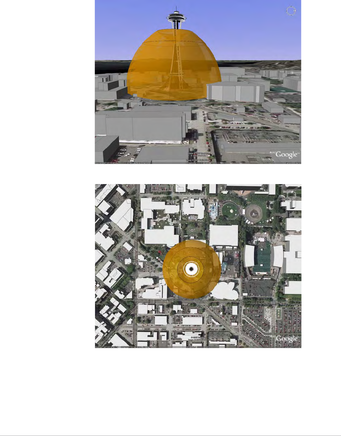
zDown-Tilt: An omni-directional antenna that focuses its energy downwards.
zSector/Patch: A directional antenna that provides a focused sector of coverage from a central point
(Example: +/- 45 degrees from a 90 degree center point).
zPanel: A flat formed antenna that directs energy to a sector of coverage. This type of antenna is often
ideal for point-to-point WDS bridging or wireless mesh backhaul applications.
Detachable Antenna Selection Tips
zIf omni-directional coverage is desired with the greatest possible horizontal range from the AP,
select one of Aruba's detachable antennas with high-gain, omni-directional coverage. Due to the
tight vertical beamwidth of high-gain, omni-directional antennas, this typically requires mounting
the antenna not more than 5 meters (16.5 feet) above the expected client locations in elevation.
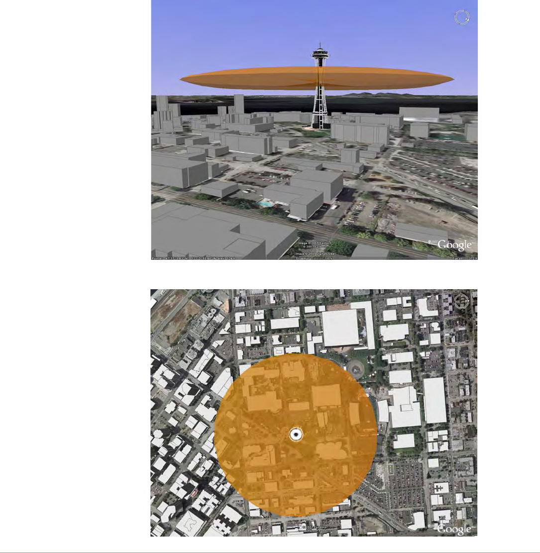
zIf omni-directional coverage is desired, but only high mounting locations are available
(approx. 5 m (16.5 feet) to 10 m (33 feet), consider the use of lower gain (3 dBi to 5 dBi) omni-
directional antennas and a denser AP deployment. The lower gain antenna will reduce the maximum
horizontal range of the AP, but will provide better vertical coverage.
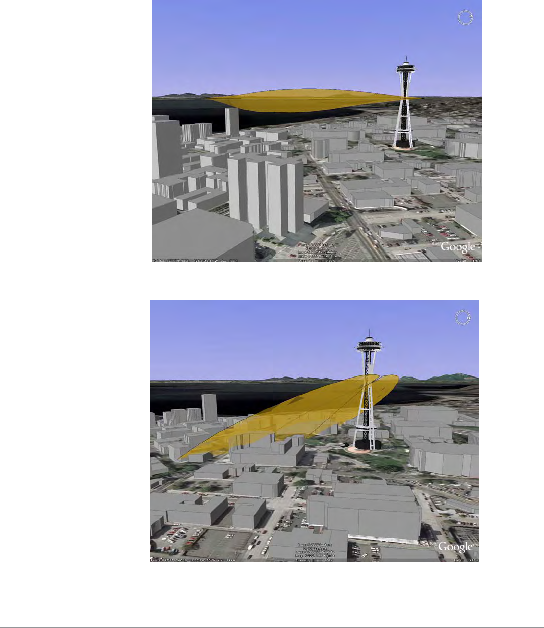
zFor very high mounting locations (>10 m/33 feet) such as light poles or monopoles, consider the use
of an omni-directional antenna with electrical downtilt. A downtilt omni-directional antenna is an
antennas that has a direction of maximum gain at approximately 45° down from horizontal.
NOTE
All figures are shown with a 100 meter (328 feet) mounting height above the ground and for a
18 Mbps coverage area.
36 | Understanding Antennas Aruba AP-85 Outdoor Access Point Series | Installation Guide
Figure 29 AP-ANT-90 E-Plane View (Side View)
Figure 30 AP-ANT-90 H-Plane View (Top View)
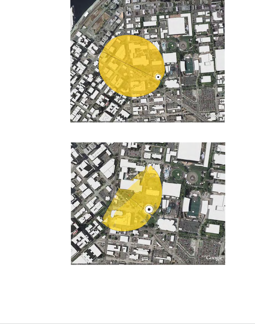
zAlternatively, for high mounting locations, high-gain sector antennas may be used with mechanical
downtilt. This will typically require the use of multiple access points per mounting location to
provide omni-directional coverage.
zIf a directional antenna is required to direct RF coverage, the detachable antenna must be capable of
supporting all of the frequency bands that require support (2.4 GHz and/or 5 GHz).
zDirectional antennas are selected to focus RF energy more efficiently to a targeted area.
zDirectional antennas are also useful in areas where the surrounding materials have high amounts of
RF attenuation or reflection and the RF signal needs to be guided in the direction of the least
Aruba AP-85 Outdoor Access Point Series | Installation Guide Understanding Antennas | 37
amount of attenuation or reflection. For example, when mounting antennas on the outside surfaces
of a building to provide coverage to outdoor spaces in front of the building, a directional antenna
can be used to direct the coverage away from the building.
High Mounting Omni-Directional Antenna Scenario (AP-ANT-80 vs. AP-ANT-90)
The AP-ANT-80 shows greater horizontal range due to its higher gain (8 dBi vs. 3 dBi) antenna, but in
this very high mounting situation, the AP-ANT-90 may be a better choice for ground level coverage
because the direction of maximum gain is directed downward toward the ground. This situation could
potentially be improved if a lower mounting elevation was available for the AP-ANT-80, ideally about
5 m above Ground.
Figure 31 AP-ANT-80 E-Plane View (Side View)
Figure 32 AP-ANT-80 H-Plane View (Top View)
38 | Understanding Antennas Aruba AP-85 Outdoor Access Point Series | Installation Guide
High Mounting Directional Antenna Scenario
The AP-ANT-82 is a high gain (12 dBi), directional antenna with a 90 degree 3 dB beamwidth in azimuth.
For this high mounting condition, this antenna provides a long range in the direction of maximum gain,
but it would require mechanical downtilt for ground level coverage.
Figure 33 AP-ANT-82 E-Plane View (Side View)
Figure 34 AP-ANT-82 with 30 Degree Downtilt E-Plane View (Side View)
Aruba AP-85 Outdoor Access Point Series | Installation Guide Understanding Antennas | 39
Figure 35 AP-ANT-82 H-Plane View (Top View)
Figure 36 AP-ANT-82 with 30 Degree Downtilt H-Plane View (Top View)

40 | Understanding Antennas Aruba AP-85 Outdoor Access Point Series | Installation Guide

Aruba AP-85 Outdoor Access Point Series | Installation Guide Product Specifications | 41
Appendix B
Product Specifications
Product Specifications
Mechanical (AP-85TX, AP-85FX, and AP-85LX)
zDevice Dimensions (HxWxD):
10.80” x 12.64” x 3.07”
274 mm x 321 mm x 78 mm
zDevice Weight: 7.40 lbs/3.36 kgs
zDevice Weight with Mounting Plate: 9.65 lbs/4.38 kgs
zDevice Weight with Mounting Plate and Mounting Bracket: 10.85 lbs/4.92 kgs
zShipping Dimensions:
15.7” x 12.2” x 9.3”
399 mm x 310 mm x 236 mm
zShipping Weight: 13.50 lbs/6.12 kgs
zTemperature:
Operating: -30ºC to 55ºC (-22ºF to 131ºF)
Storage: -40ºC to 70ºC (-40ºF to 158ºF)
zRelative Humidity: 0% to 95% non-condensing
zAltitude: 0-3000 m (0-9850 ft)
zSurvival Wind Speed: 125 mph (201 km/hr)
zMounting:
Articulating adjustable pole or mast mount kit (included)
Antenna mount bracket (optional)
zAntenna: Quad, N-type Female interfaces for external antenna support
zGround: Electrical safety/ground terminal point
zVisual Status Indicators (LEDs):
Onboard LED array for RSSI level reading
PWR - Power/Status
LINK/ACT - LAN/Network Link Status
RADIO 0 - Radio 0 Status
RADIO 1 - Radio 1 Status
RSSI (Radio 0) - RSSI Level for Radio 0
RSSI (Radio 1) - RSSI Level for Radio 1

42 | Product Specifications Aruba AP-85 Outdoor Access Point Series | Installation Guide
Electrical
AP-85TX
z1 x 10/100 Base-T auto-sensing Ethernet (RJ-45) Interface
IEEE 802.3 BaseT and 802.3u 100BaseTX compliant
PoE 48V DC Power over Ethernet (IEEE 802.3af compliant)
Serial over Ethernet (SoE)
Auto-sensing MDI/MDX
z1 x 12 V DC / up to 2.0 A power interface (for external solar supplied DC power)
z1 x Electrical Ground / Safety Terminal
zFully environmentally hardened connector types (all interfaces)
AP-85FX
z1 x 100BASE-FX data uplink port for multi-mode, dual-fiber connectivity
1310 nm wavelength, 2 km over MMF Interface
LC fiber optic connector type
z1 x 12 V DC up to 2.0 A power interface (for external solar supplied DC power)
z1 x 90-228 V~ / 500 mA auto-sensing power interface with transient power surge suppression
z1 x Serial Console Port
z1 x Electrical Ground / Safety Terminal
zFully environmentally hardened connector types (all interfaces)
AP-85LX
z1 x 100BASE-LX data uplink port for single-mode, dual-fiber connectivity
1310 nm wavelength, 10km over SMF
LC fiber optic connector type
z1 x 12 V DC up to 2.0 A power interface (for external solar supplied DC power)
z1 x 90-228 V~ / 500 mA auto-sensing power interface with transient power surge suppression
z1 x Serial Console Port
z1 x Electrical Ground / Safety Terminal
zFully environmentally hardened connector types (all interfaces)
Maximum Power Draw
Table 6 AP-85 Series Maximum Power Draw
AP Model Power Source Measurement
Condition
Max Current
(Amps)
Max Power
(Watts)
AP-85TX PoE 48 V 0.25 12
AP-85TX, AP-85FX, AP-85LX DC 12 V 0.8 9.6
AP-85FX, AP-85LX AC 240 V, 60 Hz 0.18 (RMS) 20.14
Aruba AP-85 Outdoor Access Point Series | Installation Guide Product Specifications | 43
Wireless LAN
zNetwork Standards - IEEE 802.11b, IEEE 802.11g and IEEE 802.11a
zAntenna Type - None. Detachable, outdoor rated, 2.4 or 5 GHz antenna options available
zRadio Technology:
802.11a/g - Orthogonal Frequency Division Multiplexing (OFDM)
802.11b - Direct Sequence Spread Spectrum (DSSS)
zRadio Modulation Type:
802.11a - BPSK, QPSK,16-QAM, 64-QAM
802.11b - DQPSK/CCK, DQPSK, DBPSK
802.11g - OFDM, DQPSK/CCK, DQPSK, DBPSK
zMedia Access Control - CSMA/CA with ACK
zData Rates:
802.11a - 6, 9, 12, 18, 24, 36, 48 and 54 Mbps per channel
802.11b - 1, 2, 5.5, 11 Mbps per channel
802.11g - 1, 2, 5.5, 6, 9, 11, 12, 22, 24, 33, 36 and 54 Mbps per channel
zTransmit and Available Channels: Determined by country of use and Aruba certifications within
country of use
Safety and Regulatory Compliance
Aruba provides a multi-language document containing country specific restrictions and additional
safety and regulatory information for all Aruba hardware products. This document can be viewed or
downloaded from the following location: www.arubanetworks.com/pdf/0510272-01.pdf.
Proper Disposal of Aruba Equipment
For the most current information on Global Environmental Compliance and Aruba products please see
our website at www.arubanetworks.com.
!
CAUTION
Aruba Access Points and the AP-LAR-1 lightning arrestor are required to be installed by a
professional installer. The professional installer is responsible for ensuring that grounding is
available and it meets applicable local and national electrical codes.
WARNING
Do not work on an AP and do not connect or disconnect cables during periods of lightning activity.

44 | Product Specifications Aruba AP-85 Outdoor Access Point Series | Installation Guide
Waste of Electrical and Electronic Equipment
Aruba products at end of life are subject to separate collection and treatment in the
EU Member States, Norway, and Switzerland and therefore are marked with the
symbol shown at the left (crossed-out wheelie bin). The treatment applied at end of
life of these products in these countries shall comply with the applicable national
laws of countries implementing Directive 2002/96EC on Waste of Electrical and
Electronic Equipment (WEEE).
European Union RoHS
Aruba products also comply with the EU Restriction of Hazardous Substances
Directive 2002/95/EC (RoHS). EU RoHS restricts the use of specific hazardous
materials in the manufacture of electrical and electronic equipment. Specifically,
restricted materials under the RoHS Directive are Lead (including Solder used in printed circuit
assemblies), Cadmium, Mercury, Hexavalent Chromium, and Bromine. Some Aruba products are
subject to the exemptions listed in RoHS Directive Annex 7 (Lead in solder used in printed circuit
assemblies). Products and packaging will be marked with the “RoHS” label shown at the left indicating
conformance to this Directive.
China RoHS
Aruba products also comply with China environmental declaration requirements and are
labeled with the “EFUP e” label shown at the left.

Aruba AP-85 Outdoor Access Point Series | Installation Guide Index | 45
Index
A
AC power 12
AC power cable 29
access point setup 21
accessories 13
antenna 31
beamwidth 32
detachable selection 35
directional 31
gain 32
height 17
installation 30
interfaces 10
omni-directional 31
orientation 18
pattern 32
pattern plots 34
position 18
specifications 34
understanding of 31
wireless 31
AP-85 Series
about 7
antenna interfaces 10
bottom view
AP-85 TX model 10
cable connection 28
configuration 30
front view 9
installation 22
LEDs 12
overview 9
package checklist 8
power cable connection 29
rear view 9
RJ-45 cable connection 28
software requirements 8
specifications 41
top view 10
AP-85FX
100Base-FX 11
console port 11
multi-mode fiber 11
AP-85LX
100Base-LX 11
console port 11
single-mode fiber 11
AP-85TX
10/100Base-T ports 10
interfaces 10
LAN 10
PoE 10
SPoE 10
B
beamwidth 32
C
cables 28
cabling 19, 28, 29
configuration 30
connecting cables 28, 29
connectivity 22, 30
console port 11
customer support 6
D
DC power 10, 11
DC power cable 29
deployment 15
detachable antennas 35
directional antenna 31
E
environment 19
ethernet cabling 19
F
fiber interface 11
G
gain 32
grounding 19
grounding point 11, 12

46 |Index Aruba AP-85 Outdoor Access Point Series | Installation Guide
I
installation 21, 22, 23
configuration 30
pole mounting (>3.5" Diameter) 26
pole mounting (1.5" to 3.5" Diameter) 24
positioning 27
post-installation connectivity 30
preparation 23
wall mounting 23
L
LC connector 11
LEDs 12
lightning arrestor 10, 30
line of sight 16
M
mounting 23
multi-mode fiber interface 11
N
network setup 21
N-type antenna interfaces 10
O
omni-directional antenna 31
operation
modes of 7
outdoor conditions 19
outdoor deployment 15
outdoor planning 15
overview 9
P
package checklist 8
planning 15
PoE 10
pole mounting (1.5" to 3.5" Diameter) 24
pole moutning (>3.5" Diameter) 26
positioning 27
post-installation 30
power
AC 12
DC 10, 11
power cables 29
power over ethernet 10
pre-installation 23
checklist 21
connectivity 22
network setup 21
provisioning 22
provisioning 22
R
radio interference 18
radio path planning 16
regulatory compliance 43
RF absorbers 15
RF interference sources 15
RF reflectors 15
RJ-45 cable 28
RSSI LEDs 12
RSSI levels 13
S
safety 43
scale requirements 15
serial console port 11
serial power over ethernet 10
single-mode fiber interface 11
software requirements 8
specifications 41
SPoE 10
status indicators 12
support, customer 6
W
wall mounting 23
weather 19
wireless antenna 31

Aruba AP-85 Outdoor Access Point Series | Installation Guide Index | 47

48 |Index Aruba AP-85 Outdoor Access Point Series | Installation Guide