Hewlett Packard Enterprise AP65SDR AP 65 Dual-Radio Wireless Access Point User Manual 0510260 01 AP65 IG v4 indd

Aruba Networks, Inc. AP 65 Dual-Radio Wireless Access Point 0510260 01 AP65 IG v4 indd

Contents

Users Manual

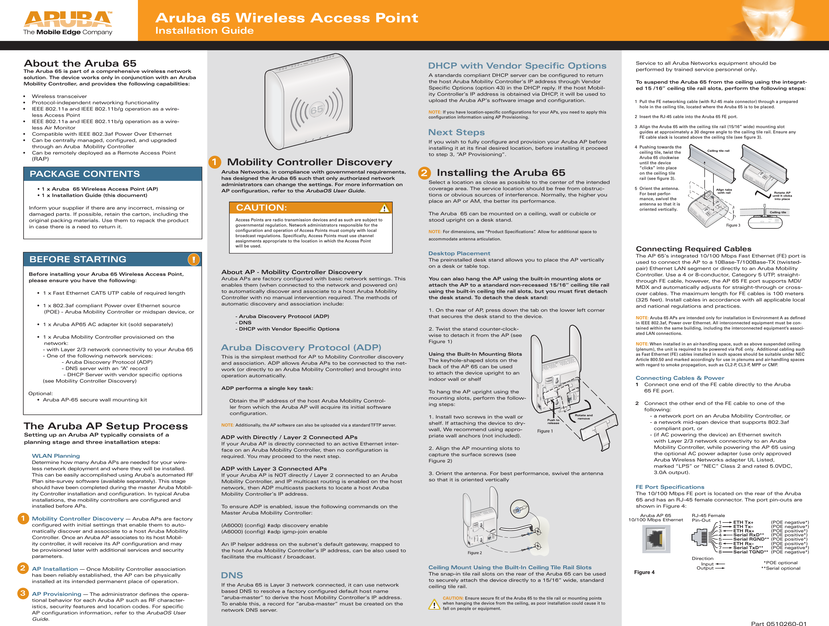
Aruba 65 Wireless Access Point Installation GuideAruba AP 65 10/100 Mbps Ethernet RJ-45 FemalePin-Out*POE optional**Serial optionalSerial RxD**   (POE positive*)Serial RGND**  (POE positive*) Serial TxD**    (POE negative*)Serial TGND**  (POE negative*)12345678ETH Tx+  (POE negative*)ETH Tx–  (POE negative*)ETH Rx+  (POE positive*)ETH Rx–    (POE positive*)  DirectionInputOutputFigure 4Push toreleaseRotate andremoveFigure 1DHCP with Vendor Specific OptionsA standards compliant DHCP server can be confi gured to return the host Aruba Mobility Controller’s IP address through Vendor Specifi c Options (option 43) in the DHCP reply. If the host Mobil-ity Controller’s IP address is obtained via DHCP, it will be used to upload the Aruba AP’s software image and confi guration.   NOTE: If you have location-specifi c confi gurations for your APs, you need to apply this confi guration information using AP Provisioning.Next StepsIf you wish to fully confi gure and provision your Aruba AP before installing it at its fi nal desired location, before installing it proceed to step 3, “AP Provisioning”.Installing the Aruba 65Select a location as close as possible to the center of the intended coverage area. The service location should be free from obstruc-tions or obvious sources of interference. Normally, the higher you place an AP or AM, the better its performance.The Aruba  65 can be mounted on a ceiling, wall or cubicle or stood upright on a desk stand.NOTE: For dimensions, see “Product Specifi cations”.  Allow for additional space to  accommodate antenna articulation.Desktop PlacementThe preinstalled desk stand allows you to place the AP vertically on a desk or table top.You can also hang the AP using the built-in mounting slots or attach the AP to a standard non-recessed 15/16” ceiling tile rail using the built-in ceiling tile rail slots, but you must fi rst detach the desk stand. To detach the desk stand:1. On the rear of AP, press down the tab on the lower left corner that secures the desk stand to the device.2. Twist the stand counter-clock-wise to detach it from the AP (see Figure 1)Using the Built-In Mounting SlotsThe keyhole-shaped slots on the back of the AP 65 can be used to attach the device upright to an indoor wall or shelfTo hang the AP upright using the mounting slots, perform the follow-ing steps:1. Install two screws in the wall or shelf. If attaching the device to dry-wall, We recommend using appro-priate wall anchors (not included).2. Align the AP mounting slots to capture the surface screws (see Figure 2)3. Orient the antenna. For best performance, swivel the antenna so that it is oriented verticallyCeiling Mount Using the Built-In Ceiling Tile Rail SlotsThe snap-in tile rail slots on the rear of the Aruba 65 can be used to securely attach the device directly to a 15/16” wide, standard ceiling tile rail.CAUTION: Ensure secure fi t of the Aruba 65 to the tile rail or mounting points when hanging the device from the ceiling, as poor installation could cause it to fall on people or equipment. PACKAGE CONTENTS  • 1 x Aruba  65 Wireless Access Point (AP)  • 1 x Installation Guide (this document)Inform your supplier if there are any incorrect, missing or damaged parts. If possible, retain the carton, including the original packing materials. Use them to repack the product in case there is a need to return it.BEFORE STARTINGBefore installing your Aruba 65 Wireless Access Point, please ensure you have the following:  •  1 x Fast Ethernet CAT5 UTP cable of required length  •  1 x 802.3af compliant Power over Ethernet source        (POE) - Aruba Mobility Controller or midspan device, or  •  1 x Aruba AP65 AC adapter kit (sold separately)  •  1 x Aruba Mobility Controller provisioned on the         network:    - with Layer 2/3 network connectivity to your Aruba 65    - One of the following network services:      - Aruba Discovery Protocol (ADP)      - DNS server with an “A” record        - DHCP Server with vendor specifi c options    (see Mobility Controller Discovery) Optional:  •  Aruba AP-65 secure wall mounting kitMobility Controller DiscoveryAruba Networks, in compliance with governmental requirements, has designed the Aruba 65 such that only authorized network administrators can change the settings. For more information on AP confi guration, refer to the ArubaOS User Guide.About AP - Mobility Controller DiscoveryAruba APs are factory confi gured with basic network settings. This enables them (when connected to the network and powered on) to automatically discover and associate to a host Aruba Mobility Controller with no manual intervention required. The methods of automatic discovery and association include:    - Aruba Discovery Protocol (ADP)   - DNS    - DHCP with Vendor Specifi c OptionsAruba Discovery Protocol (ADP)This is the simplest method for AP to Mobility Controller discovery and association. ADP allows Aruba APs to be connected to the net-work (or directly to an Aruba Mobility Controller) and brought into operation automatically.ADP performs a single key task:Obtain the IP address of the host Aruba Mobility Control-ler from which the Aruba AP will acquire its initial software  confi guration. NOTE: Additionally, the AP software can also be uploaded via a standard TFTP server.ADP with Directly / Layer 2 Connected APsIf your Aruba AP is directly connected to an active Ethernet inter-face on an Aruba Mobility Controller, then no confi guration is required. You may proceed to the next step.ADP with Layer 3 Connected APsIf your Aruba AP is NOT directly / Layer 2 connected to an Aruba Mobility Controller, and IP multicast routing is enabled on the host network, then ADP multicasts packets to locate a host Aruba Mobility Controller’s IP address. To ensure ADP is enabled, issue the following commands on the Master Aruba Mobility Controller:(A6000) (confi g) #adp discovery enable(A6000) (confi g) #adp igmp-join enableAn IP helper address on the subnet’s default gateway, mapped to the host Aruba Mobility Controller’s IP address, can be also used to facilitate the multicast / broadcast. DNSIf the Aruba 65 is Layer 3 network connected, it can use network based DNS to resolve a factory confi gured default host name “aruba-master” to derive the host Mobility Controller’s IP address. To enable this, a record for “aruba-master” must be created on the network DNS server.CAUTION: Access Points are radio transmission devices and as such are subject to governmental regulation. Network administrators responsible for the confi guration and operation of Access Points must comply with local broadcast regulations. Specifi cally, Access Points must use channel assignments appropriate to the location in which the Access Point will be used. Part 0510260-01Service to all Aruba Networks equipment should beperformed by trained service personnel only.To suspend the Aruba 65 from the ceiling using the integrat-ed 15 /16” ceiling tile rail slots, perform the following steps:Connecting Required CablesThe AP 65’s integrated 10/100 Mbps Fast Ethernet (FE) port is used to connect the AP to a 10Base-T/100Base-TX (twisted-pair) Ethernet LAN segment or directly to an Aruba Mobility Controller. Use a 4 or 8-conductor, Category 5 UTP, straight-through FE cable, however, the AP 65 FE port supports MDI/MDX and automatically adjusts for straight-through or cross-over cables. The maximum length for FE cables is 100 meters (325 feet). Install cables in accordance with all applicable local and national regulations and practices.NOTE: Aruba 65 APs are intended only for installation in Environment A as defi ned in IEEE 802.3af, Power over Ethernet. All interconnected equipment must be con-tained within the same building, including the interconnected equipment’s associ-ated LAN connections. NOTE: When installed in an air-handling space, such as above suspended ceiling (plenum), the unit is required to be powered via PoE only.  Additional cabling such as Fast Ethernet (FE) cables installed in such spaces should be suitable under NEC Article 800.50 and marked accordingly for use in plenums and air-handling spaces with regard to smoke propagation, such as CL2-P, CL3-P, MPP or CMP.Connecting Cables & Power1   Connect one end of the FE cable directly to the Aruba  65 FE port.2   Connect the other end of the FE cable to one of the following:    - a network port on an Aruba Mobility Controller, or  -  a network mid-span device that supports 802.3af compliant port, or   -  (if AC powering the device) an Ethernet switch with Layer 2/3 network connectivity to an Aruba Mobility Controller, while powering the AP 65 using the optional AC power adapter (use only approved Aruba Wireless Networks adapter UL Listed, marked “LPS” or “NEC” Class 2 and rated 5.0VDC, 3.0A output).FE Port Specifi cationsThe 10/100 Mbps FE port is located on the rear of the Aruba  65 and has an RJ-45 female connector. The port pin-outs are shown in Figure 4:AAAAAruArubAbout the Aruba 65The Aruba 65 is part of a comprehensive wireless network solution. The device works only in conjunction with an Aruba Mobility Controller, and provides the following capabilities:• Wireless transceiver•  Protocol-independent networking functionality•  IEEE 802.11a and IEEE 802.11b/g operation as a wire-less Access Point•  IEEE 802.11a and IEEE 802.11b/g operation as a wire-less Air Monitor•  Compatible with IEEE 802.3af Power Over Ethernet •  Can be centrally managed, confi gured, and upgraded through an Aruba  Mobility Controller•  Can be remotely deployed as a Remote Access Point (RAP)1   Pull the FE networking cable (with RJ-45 male connector) through a prepared hole in the ceiling tile, located where the Aruba 65 is to be placed.2  Insert the RJ-45 cable into the Aruba 65 FE port.3    Align the Aruba 65 with the ceiling tile rail (15/16” wide) mounting slot guides at approximately a 30 degree angle to the cailing tile rail. Ensure any FE cable slack is located above the ceiling tile (see fi gure 3).4    Pushing towards the ceiling tile, twist the Aruba 65 clockwise until the device “clicks” into place on the ceiling tile rail (see fi gure 3).5   Orient the antenna. For best perfor-mance, swivel the antenna so that it is oriented vertically.Ceiling tile railRotate APuntil it clicksinto placeAlign tabswith railCeiling tileFigure 3 Figure 2AAThe Aruba AP Setup ProcessSetting up an Aruba AP typically consists of a planning stage and three installation steps: WLAN Planning   Determine how many Aruba APs are needed for your wire-less network deployment and where they will be installed. This can be easily accomplished using Aruba’s automated RF Plan site-survey software (available separately). This stage should have been completed during the master Aruba Mobil-ity Controller installation and confi guration. In typical Aruba installations, the mobility controllers are confi gured and installed before APs.Mobility Controller Discovery — Aruba APs are factory confi gured with initial settings that enable them to auto-matically discover and associate to a host Aruba Mobility Controller. Once an Aruba AP associates to its host Mobil-ity controller, it will receive its AP confi guration and may be provisioned later with additional services and security parameters.  AP Installation — Once Mobility Controller association has been reliably established, the AP can be physically installed at its intended permanent place of operation. AP Provisioning — The administrator defi nes the opera-tional behavior for each Aruba AP such as RF character-istics, security features and location codes. For specifi c AP confi guration information, refer to the ArubaOS User Guide.12312
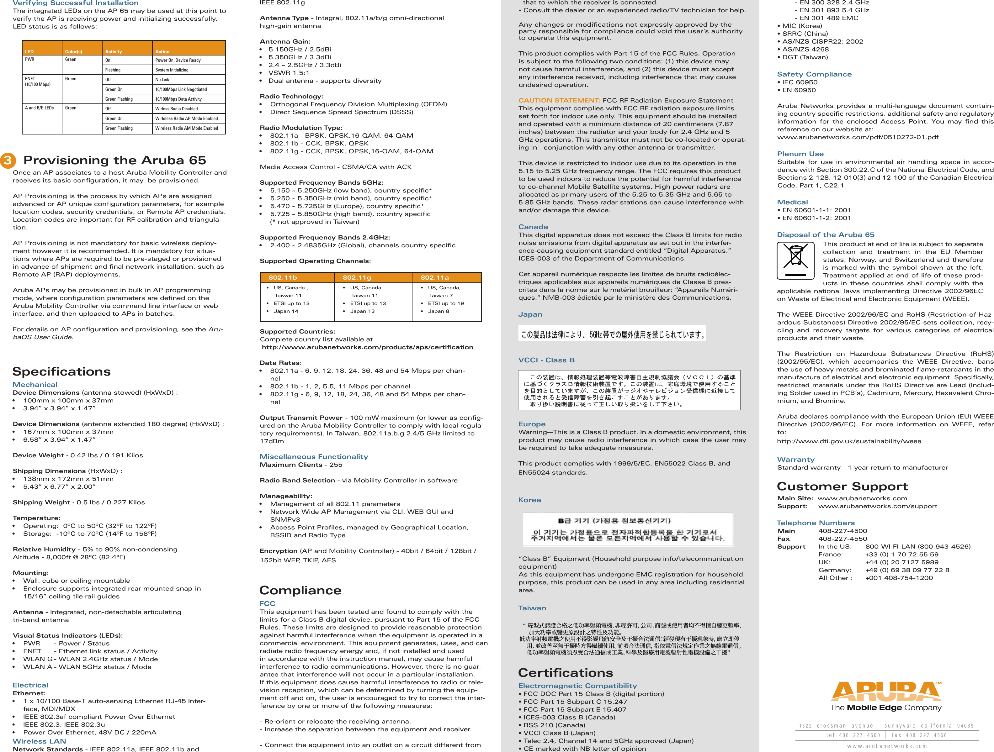
      1322  crossman  avenue sunnyvale  california  94089tel  408  227  4500 fax  408  227  4550www.arubanetworks.comVerifying Successful InstallationThe integrated LEDs on the AP 65 may be used at this point to verify the AP is receiving power and initializing successfully. LED status is as follows:Provisioning the Aruba 65Once an AP associates to a host Aruba Mobility Controller and receives its basic confi guration, it may  be provisioned. AP Provisioning is the process by which APs are assigned advanced or AP unique confi guration parameters, for example  location codes, security credentials, or Remote AP credentials. Location codes are important for RF calibration and triangula-tion. AP Provisioning is not mandatory for basic wireless deploy-ment however it is recommended. It is mandatory for situa-tions where APs are required to be pre-staged or provisioned in advance of shipment and fi nal network installation, such as Remote AP (RAP) deployments. Aruba APs may be provisioned in bulk in AP programming mode, where confi guration parameters are defi ned on the Aruba Mobility Controller via command line interface or web interface, and then uploaded to APs in batches. For details on AP confi guration and provisioning, see the Aru-baOS User Guide.SpecificationsMechanicalDevice Dimensions (antenna stowed) (HxWxD) : •  100mm x 100mm x 37mm•  3.94” x 3.94” x 1.47”Device Dimensions (antenna extended 180 degree) (HxWxD) :•  167mm x 100mm x 37mm•  6.58” x 3.94” x 1.47”Device Weight - 0.42 lbs / 0.191 KilosShipping Dimensions (HxWxD) : •  138mm x 172mm x 51mm•  5.43” x 6.77” x 2.00”Shipping Weight - 0.5 lbs / 0.227 KilosTemperature:  •  Operating:  0ºC to 50ºC (32ºF to 122ºF)•  Storage:  -10ºC to 70ºC (14ºF to 158ºF) Relative Humidity - 5% to 90% non-condensingAltitude - 8,000ft @ 28ºC (82.4ºF)Mounting:•  Wall, cube or ceiling mountable•  Enclosure supports integrated rear mounted snap-in 15/16” ceiling tile rail guidesAntenna - Integrated, non-detachable articulating tri-band antennaVisual Status Indicators (LEDs):•  PWR   - Power / Status•  ENET   - Ethernet link status / Activity•  WLAN G - WLAN 2.4GHz status / Mode •  WLAN A - WLAN 5GHz status / ModeElectricalEthernet: •  1 x 10/100 Base-T auto-sensing Ethernet RJ-45 Inter-face, MDI/MDX•  IEEE 802.3af compliant Power Over Ethernet•  IEEE 802.3, IEEE 802.3u•  Power Over Ethernet, 48V DC / 220mA Wireless LANNetwork Standards - IEEE 802.11a, IEEE 802.11b and   - EN 300 328 2.4 GHz  - EN 301 893 5.4 GHz  - EN 301 489 EMC• MIC (Korea)• SRRC (China)• AS/NZS CISPR22: 2002• AS/NZS 4268• DGT (Taiwan)Safety Compliance• IEC 60950• EN 60950Aruba Networks provides a multi-language document contain-ing country specifi c restrictions, additional safety and regulatory information for the enclosed Access Point. You may fi nd  this reference on our website at:www.arubanetworks.com/pdf/0510272-01.pdfPlenum UseSuitable for use in environmental air handling space in accor-dance with Section 300.22.C of the National Electrical Code, and Sections 2-128, 12-010(3) and 12-100 of the Canadian Electrical Code, Part 1, C22.1Medical• EN 60601-1-1: 2001• EN 60601-1-2: 2001Disposal of the Aruba 65This product at end of life is subject to separate  collection and treatment in the EU Member states, Norway, and Switzerland and therefore is marked with the symbol shown at the left. Treatment applied at end of life of these prod-ucts in these countries shall comply with the applicable national laws implementing Directive 2002/96EC on Waste of Electrical and Electronic Equipment (WEEE).The WEEE Directive 2002/96/EC and RoHS (Restriction of Haz-ardous Substances) Directive 2002/95/EC sets collection, recy-cling and recovery targets for various categories of electrical products and their waste.The Restriction on Hazardous Substances Directive (RoHS)       (2002/95/EC), which accompanies the WEEE Directive, bans the use of heavy metals and brominated fl ame-retardants in the manufacture of electrical and electronic equipment. Specifi cally, restricted materials under the RoHS Directive are Lead (Includ-ing Solder used in PCB’s), Cadmium, Mercury, Hexavalent Chro-mium, and Bromine.Aruba declares compliance with the European Union (EU) WEEE Directive (2002/96/EC). For more information on WEEE, refer to:http://www.dti.gov.uk/sustainability/weeeWarrantyStandard warranty - 1 year return to manufacturerCustomer SupportMain Site:  www.arubanetworks.comSupport: www.arubanetworks.com/supportTelephone NumbersMain        408-227-4500Fax          408-227-4550Support    In the US:  800-WI-FI-LAN (800-943-4526)    France:          +33 (0) 1 70 72 55 59    UK:    +44 (0) 20 7127 5989    Germany:  +49 (0) 69 38 09 77 22 8    All Other :   +001 408-754-1200IEEE 802.11gAntenna Type - Integral, 802.11a/b/g omni-directional high-gain antennaAntenna Gain:•   5.150GHz / 2.5dBi•   5.350GHz / 3.3dBi•   2.4 ~ 2.5GHz / 3.3dBi•   VSWR 1.5:1•   Dual antenna - supports diversityRadio Technology:•  Orthogonal Frequency Division Multiplexing (OFDM) •  Direct Sequence Spread Spectrum (DSSS)Radio Modulation Type:•  802.11a - BPSK, QPSK,16-QAM, 64-QAM•  802.11b - CCK, BPSK, QPSK•  802.11g - CCK, BPSK, QPSK,16-QAM, 64-QAMMedia Access Control - CSMA/CA with ACKSupported Frequency Bands 5GHz:•  5.150 ~ 5.250GHz (low band), country specifi c*•  5.250 ~ 5.350GHz (mid band), country specifi c*•  5.470 ~ 5.725GHz (Europe), country specifi c*•  5.725 ~ 5.850GHz (high band), country specifi c      (* not approved in Taiwan)Supported Frequency Bands 2.4GHz: •  2.400 ~ 2.4835GHz (Global), channels country specifi cSupported Operating Channels:Supported Countries: Complete country list available at http://www.arubanetworks.com/products/aps/certifi cationData Rates: •  802.11a - 6, 9, 12, 18, 24, 36, 48 and 54 Mbps per chan-nel•  802.11b - 1, 2, 5.5, 11 Mbps per channel•  802.11g - 6, 9, 12, 18, 24, 36, 48 and 54 Mbps per chan-nelOutput Transmit Power - 100 mW maximum (or lower as confi g-ured on the Aruba Mobility Controller to comply with local regula-tory requirements). In Taiwan, 802.11a.b.g 2.4/5 GHz limited to 17dBmMiscellaneous Functionality  Maximum Clients - 255   Radio Band Selection - via Mobility Controller in software   Manageability: •  Management of all 802.11 parameters•  Network Wide AP Management via CLI, WEB GUI and SNMPv3• Access Point Profi les, managed by Geographical Location, BSSID and Radio Type Encryption (AP and Mobility Controller) - 40bit / 64bit / 128bit / 152bit WEP, TKIP, AES ComplianceFCCThis equipment has been tested and found to comply with the limits for a Class B digital device, pursuant to Part 15 of the FCC Rules. These limits are designed to provide reasonable protection against harmful interference when the equipment is operated in a commercial environment. This equipment generates, uses, and can radiate radio frequency energy and, if not installed and used in accordance with the instruction manual, may cause harmful interference to radio communications. However, there is no guar-antee that interference will not occur in a particular installation.If this equipment does cause harmful interference to radio or tele-vision reception, which can be determined by turning the equip-ment off and on, the user is encouraged to try to correct the inter-ference by one or more of the following measures:- Re-orient or relocate the receiving antenna.- Increase the separation between the equipment and receiver.- Connect the equipment into an outlet on a circuit different from    that to which the receiver is connected.- Consult the dealer or an experienced radio/TV technician for help.Any changes or modifi cations not expressly approved by the party responsible for compliance could void the user’s authority to operate this equipment.This product complies with Part 15 of the FCC Rules. Operation is subject to the following two conditions: (1) this device may not cause harmful interference, and (2) this device must accept any interference received, including interference that may cause    undesired operation.CAUTION STATEMENT: FCC RF Radiation Exposure StatementThis equipment complies with FCC RF radiation exposure limits set forth for indoor use only. This equipment should be installed and operated with a minimum distance of 20 centimeters (7.87 inches) between the radiator and your body for 2.4 GHz and 5  GHz operations. This transmitter must not be co-located or operat-ing in   conjunction with any other antenna or transmitter.This device is restricted to indoor use due to its operation in the 5.15 to 5.25 GHz frequency range. The FCC requires this product to be used indoors to reduce the potential for harmful interference to co-channel Mobile Satellite systems. High power radars are allocated as primary users of the 5.25 to 5.35 GHz and 5.65 to 5.85 GHz bands. These radar stations can cause interference with and/or damage this device.CanadaThis digital apparatus does not exceed the Class B limits for radio noise emissions from digital apparatus as set out in the interfer-ence-causing equipment standard entitled “Digital Apparatus,” ICES-003 of the Department of Communications.Cet appareil numérique respecte les limites de bruits radioélec-triques applicables aux appareils numériques de Classe B pres-crites dans la norme sur le matériel brouilleur: “Appareils Numéri-ques,” NMB-003 édictée par le ministère des Communications.JapanVCCI - Class BEuropeWarning—This is a Class B product. In a domestic environment, this product may cause radio interference in which case the user may be required to take adequate measures.This product complies with 1999/5/EC, EN55022 Class B, and EN55024 standards.Korea“Class B” Equipment (Household purpose info/telecommunication equipment)As this equipment has undergone EMC registration for household purpose, this product can be used in any area including residential area.Ta i w a nCertificationsElectromagnetic Compatibility• FCC DOC Part 15 Class B (digital portion)• FCC Part 15 Subpart C 15.247• FCC Part 15 Subpart E 15.407• ICES-003 Class B (Canada)• RSS 210 (Canada)• VCCI Class B (Japan)• Telec 2.4, Channel 14 and 5GHz approved (Japan)• CE marked with NB letter of opinion  “ 經型式認證合格之低功率射頻電機,非經許可,公司、商號或使用者均不得擅自變更頻率、     加大功率或變更原設計之特性及功能。低功率射頻電機之使用不得影響飛航安全及干擾合法通信;經發現有干擾現象時,應立即停     用,並改善至無干擾時方得繼續使用。前項合法通信,指依電信法規定作業之無線電通信。     低功率射頻電機須忍受合法通信或工業、科學及醫療用電波輻射性電機設備之干擾”3LED Color(s) Activity ActionPWR Green On Power On, Device ReadyFlashing System InitializingENET (10/100 Mbps)Green Off No LinkGreen On 10/100Mbps Link NegotiatedGreen Flashing 10/100Mbps Data ActivityA and B/G LEDs Green Off Wirless Radio DisabledGreen On Wirleless Radio AP Mode EnabledGreen Flashing Wireless Radio AM Mode Enabled802.11b 802.11g 802.11a•   US, Canada ,      Taiwan 11 •   ETSI up to 13•   Japan 14•   US, Canada,      Taiwan 11 •   ETSI up to 13•   Japan 13•   US, Canada,      Taiwan 7 •   ETSI up to 19•   Japan 8

Navigation menu